
If you’re looking to showcase sensor readings in your ESP8266 projects without relying on serial output, consider using an I2C LCD display instead! It uses just two GPIO pins, which can also be utilized for other I2C devices.
Hardware Overview
An I2C LCD display typically comprises a character LCD display based on the HD44780 and an I2C LCD adapter. Let’s delve into each component individually.
Character LCD Display
As the name suggests, these LCDs are primarily designed for text or character display. For instance, a 16×2 character LCD features an LED backlight and can exhibit 32 ASCII characters across two rows, with each row accommodating 16 characters.
Upon close examination, you’ll notice tiny rectangles representing each character on the display, composed of pixels. Each of these rectangles forms a grid of 5×8 pixels.
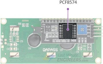
I2C LCD Adapter
Central to the adapter is an 8-bit I/O expander chip called PCF8574. This chip translates I2C data from an ESP8266 into parallel data necessary for operating an LCD display.
Moreover, the board includes a small trimpot for precise adjustments to the display’s contrast.
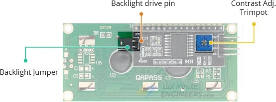
Furthermore, there’s a jumper on the board supplying power to the backlight. For controlling the backlight’s brightness, you can disconnect the jumper and apply external voltage to the designated header pin labeled ‘LED’.
I2C Address Configuration for the LCD
When employing multiple devices on the same I2C bus, it may become necessary to assign a unique I2C address to the LCD adapter to prevent conflicts with other I2C devices.
To accomplish this, the adapter incorporates three solder jumpers (A0, A1, and A2) or solder pads.

Each of these is utilized to fix the address. If a jumper is bridged with solder, it configures the address.
An important consideration is that various companies produce the same PCF8574 chip, such as Texas Instruments and NXP Semiconductors. Consequently, the I2C address of your LCD is contingent upon the chip manufacturer.
For LCDs equipped with Texas Instruments’ PCF8574 chip:
According to the Texas Instruments datasheet, the three address selection bits (A0, A1, and A2) are positioned at the end of the 7-bit I2C address register.
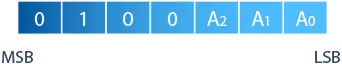
As there are 3 address inputs capable of assuming 2 states, either HIGH or LOW, a total of 8 (2^3) different combinations (addresses) can be created.
By default, all 3 address inputs are set HIGH using onboard pullups, resulting in the PCF8574 having a default I2C address of 0100111 in binary or 0x27 in hexadecimal.
Bridging the solder jumpers pulls the address inputs LOW. If all three jumpers are bridged, the address becomes 0x20. The range of all possible addresses spans from 0x20 to 0x27. Refer to the illustration below.

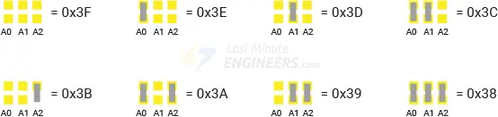
For LCDs featuring NXP Semiconductors’ PCF8574 chip:
According to the NXP Semiconductors datasheet, the three address selection bits (A0, A1, and A2) are similarly positioned at the end of the 7-bit I2C address register, but the other bits in the address register differ.

With 3 address inputs capable of being HIGH or LOW, a total of 8 (2^3) different combinations (addresses) can be generated.
By default, all 3 address inputs are pulled HIGH using onboard pullups, resulting in the PCF8574 having a default I2C address of 0111111 in binary or 0x3F in hexadecimal.
Bridging the solder jumpers pulls the address inputs LOW. If all three jumpers are bridged, the address becomes 0x38. The range of all possible addresses spans from 0x38 to 0x3F. Please refer to the illustration below.
I2C LCD display Pinout
An I2C LCD display features only 4 pins for external connections. These connections are outlined below:
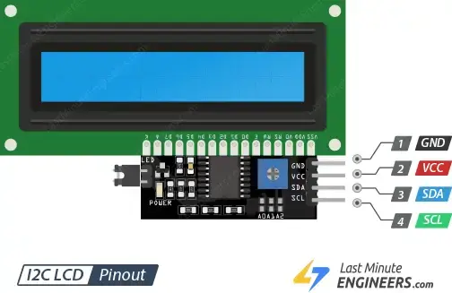
- GND: This pin serves as the ground connection. Connect it to the ground pin of the ESP8266.
- VCC: This pin supplies power to both the module and LCD. Connect it either to the ESP8266’s VIN pin or to an external 5V power supply.
- SDA: This pin is designated as the I2C data pin. Connect it to the ESP8266’s corresponding I2C data pin.
- SCL: This pin functions as the I2C clock pin. Connect it to the ESP8266’s corresponding I2C clock pin.
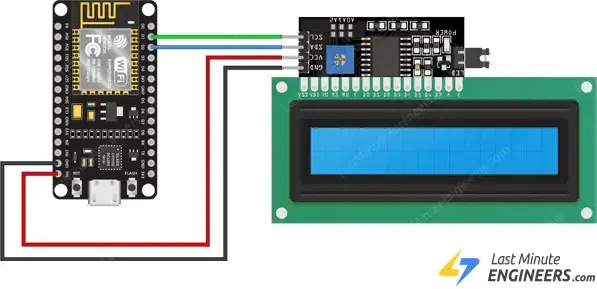
Wiring an I2C LCD Display to an ESP8266
Connecting an I2C LCD to an ESP8266 is straightforward, requiring only 4 pins to be connected. Begin by linking the VCC pin to the VIN pin on the ESP8266 and the GND pin to ground.
Next, focus on the pins utilized for I2C communication. Utilize the default I2C pins (GPIO#4 and GPIO#5) of the ESP8266. Connect the SDA pin to the ESP8266’s D2 (GPIO#4) and the SCL pin to the ESP8266’s D1 (GPIO#5).
The following table outlines the pin connections:
| I2C LCD | ESP8266 |
| VCC | VIN |
| GND | GND |
| SCL | D1 |
| SDA | D2 |
The following diagram shows you how to wire everything up.
Adjusting The LCD Contrast
Upon connecting the LCD, it’s essential to adjust its contrast. Locate the potentiometer on the I2C module, which you can adjust using a small screwdriver.
Connect the ESP8266’s USB connector to power the LCD. You’ll observe the backlight turning on. Now, by rotating the potentiometer’s knob, you’ll gradually see the first row of rectangles appearing. When this happens, congratulations! Your LCD is functioning correctly.
Once the contrast adjustment is done, you can proceed with programming the LCD.
Library Installation
To operate an I2C LCD, you must install a library named LiquidCrystal_I2C.
To install the library, go to Sketch > Include Libraries > Manage Libraries… Allow the Library Manager to download the library index and update the list of installed libraries.
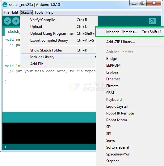
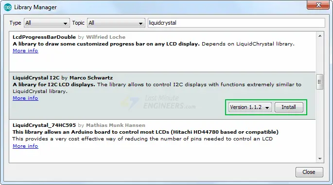
Filter your search by typing ‘liquidcrystal’. Several entries will appear. Look for the LiquidCrystal I2C library by Marco Schwartz. Click on that entry, then select Install.
Determining the I2C Address
As mentioned earlier, the I2C address of your LCD depends on its manufacturer. If your LCD utilizes a Texas Instruments’ PCF8574 chip, its default I2C address is 0x27Hex. Conversely, if your LCD employs an NXP Semiconductors’ PCF8574 chip, its default I2C address is 0x3FHex.
Therefore, your LCD likely has either the I2C address 0x27Hex or 0x3FHex. Nonetheless, it’s recommended to verify the actual I2C address of the LCD before proceeding with its usage. Fortunately, there’s a simple method to accomplish this. Below is a straightforward I2C scanner sketch that scans your I2C bus and reports the address of each detected I2C device.
#include <Wire.h>

void setup() {
  Serial.begin (115200);

  // Leonardo: wait for serial port to connect
  while (!Serial)
    {
    }

  Serial.println ();
  Serial.println ("I2C scanner. Scanning ...");
  byte count = 0;

  Wire.begin();
  for (byte i = 8; i < 120; i++)
  {
    Wire.beginTransmission (i);
    if (Wire.endTransmission () == 0)
      {
      Serial.print ("Found address: ");
      Serial.print (i, DEC);
      Serial.print (" (0x");
      Serial.print (i, HEX);
      Serial.println (")");
      count++;
      delay (1);  // maybe unneeded?
      } // end of good response
  } // end of for loop
  Serial.println ("Done.");
  Serial.print ("Found ");
  Serial.print (count, DEC);
  Serial.println (" device(s).");
}  // end of setup

void loop() {}
Once you upload the code, open the serial monitor at a baud rate of 115200 and press the EN button on the ESP8266. This will display the I2C address of your I2C LCD display.

Please make a note of this address, as it will be necessary for subsequent examples.
Basic Example Code – Hello World!
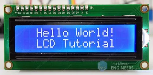
The following test sketch will display ‘Hello World!’ on the first line of the LCD and ‘LCD Tutorial’ on the second line.
Before uploading the sketch, you need to make a slight modification to tailor it to your setup. You must provide the I2C address of your LCD and the dimensions of the display to the constructor of the LiquidCrystal_I2C class. If you are using a 16×2 character LCD, input 16 and 2; if you’re using a 20×4 LCD, input 20 and 4. You understand the gist!
// enter the I2C address and the dimensions of your LCD here
LiquidCrystal_I2C lcd(0x3F, 16, 2);
Once you’ve made these adjustments, proceed to test the sketch.
#include <LiquidCrystal_I2C.h>

LiquidCrystal_I2C lcd(0x3F,16,2);  // set the LCD address to 0x3F for a 16 chars and 2 line display

void setup() {
  lcd.init();
  lcd.clear();
  lcd.backlight();      // Make sure backlight is on

  // Print a message on both lines of the LCD.
  lcd.setCursor(2,0);   //Set cursor to character 2 on line 0
  lcd.print("Hello world!");

  lcd.setCursor(2,1);   //Move cursor to character 2 on line 1
  lcd.print("LCD Tutorial");
}

void loop() {
}
If all goes according to plan, you should observe something similar to this displayed on the screen.
Code Explanation:
The sketch commences by importing the LiquidCrystal_I2C library.
#include <LiquidCrystal_I2C.h>
Initially, an instance of the LiquidCrystal_I2C class is instantiated. This instance requires three parameters: LiquidCrystal_I2C(address, columns, rows). Here, you should input the address you discovered earlier and the dimensions of the display.
LiquidCrystal_I2C lcd(0x3F,16,2);
Once a LiquidCrystal_I2C object is defined, you can utilize the object methods tailored for the LCD.
In the ‘setup’ section, three functions are invoked. The first function is init(). It initializes the LCD object. The second function is clear(). This function clears the LCD screen and relocates the cursor to the upper left corner. Lastly, the backlight() function switches on the LCD backlight.
lcd.init();
lcd.clear();
lcd.backlight();
Subsequently, the cursor position is set to the third column of the first row using the function lcd.setCursor(2, 0). The cursor position denotes where the new text will appear on the LCD. The top-left corner is considered as col=0, row=0.
lcd.setCursor(2,0);
Following this, the string ‘Hello World!’ is printed by invoking the print() function.
lcd.print("Hello world!");
Similarly, the subsequent two lines of code adjust the cursor position to the third column of the second row and print ‘LCD Tutorial’ on the LCD.
lcd.setCursor(2,1);
lcd.print("LCD Tutorial");
Additional Useful Functions of the Library
The LiquidCrystal_I2C library offers several handy functions compatible with LiquidCrystal_I2C objects. Below are some of them:
- The
lcd.home()function relocates the cursor to the upper-left corner of the LCD screen without erasing the display.
- The
lcd.blink()function presents a blinking block of 5×8 pixels at the cursor’s position where the next character is to be written.
- The
lcd.cursor()function exhibits an underscore (line) at the cursor’s position where the next character is to be written.
- The
lcd.noBlink()function disables the blinking effect of the LCD cursor.
- The
lcd.noCursor()function conceals the LCD cursor from view.
- The
lcd.scrollDisplayRight()function shifts the contents of the display one space to the right. To maintain continuous text scrolling, this function should be used within a for loop.
- The
lcd.scrollDisplayLeft()function shifts the contents of the display one space to the left. Similar to the previous function, this should also be utilized within a for loop for continuous scrolling.
Create and Display Custom Characters
If you find the characters displayed on the LCD to be dull and uninteresting, you have the option to create your own custom characters (also known as glyphs) and symbols for your LCD. This feature proves to be incredibly useful when you need to display a character that is not included in the standard ASCII character set.
As explained earlier in this tutorial, a character is constructed from a 5×8 pixel matrix. Therefore, you must define your custom character within this matrix. You can accomplish this using the createChar() function.
To utilize createChar(), you first need to establish an array of 8 bytes. Each byte in the array represents a row of characters in the 5×8 matrix. The values 0 and 1 in a byte indicate which pixel in the row should be turned ON and which should be turned OFF.
All these user-defined characters are stored in the CGRAM (Character Generator RAM) of the LCD.
All LCDs based on the Hitachi HD44780 controller feature two types of memory – CGROM (Character Generator ROM) and CGRAM (Character Generator RAM).
CGROM is non-volatile memory and cannot be altered, whereas CGRAM is volatile memory and can be modified at any time. CGROM is utilized to store all permanent fonts that are displayed using their ASCII codes. For instance, if we send 0x41 to the LCD, the letter ‘A’ will be printed on the display.
CGRAM is another memory used to store user-defined characters. This RAM is limited to 64 bytes. For a 5×8 pixel-based LCD, only 8 user-defined characters can be stored in CGRAM. And for a 5×10 pixel-based LCD, only 4 user-defined characters can be stored.
Custom Character Generator
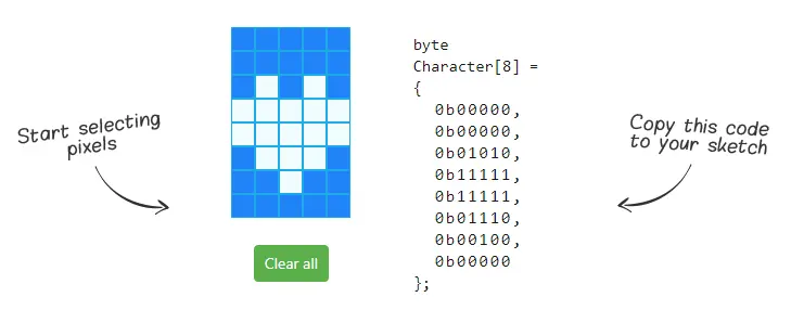
Creating custom characters has never been easier! We have developed a small application known as the Custom Character Generator. Do you see the blue grid below? You can click on any 5×8 pixel to toggle it on or off. As you click, the code for the character is generated next to the grid. This code can be directly used in your ESP8266 sketch.
Your imagination knows no bounds. The only restriction is that the LiquidCrystal_I2C library supports only eight custom characters. But don’t let that discourage you; look at the bright side – at least we have eight characters.
ESP8266 Example Code
The following code demonstrates how to create custom characters and display them on an LCD.
#include <LiquidCrystal_I2C.h>

LiquidCrystal_I2C lcd(0x3F, 16, 2);  // set the LCD address to 0x3F for a 16 chars and 2 line display

// make some custom characters:
byte Heart[8] = {
0b00000,
0b01010,
0b11111,
0b11111,
0b01110,
0b00100,
0b00000,
0b00000
};

byte Bell[8] = {
0b00100,
0b01110,
0b01110,
0b01110,
0b11111,
0b00000,
0b00100,
0b00000
};


byte Alien[8] = {
0b11111,
0b10101,
0b11111,
0b11111,
0b01110,
0b01010,
0b11011,
0b00000
};

byte Check[8] = {
0b00000,
0b00001,
0b00011,
0b10110,
0b11100,
0b01000,
0b00000,
0b00000
};

byte Speaker[8] = {
0b00001,
0b00011,
0b01111,
0b01111,
0b01111,
0b00011,
0b00001,
0b00000
};


byte Sound[8] = {
0b00001,
0b00011,
0b00101,
0b01001,
0b01001,
0b01011,
0b11011,
0b11000
};


byte Skull[8] = {
0b00000,
0b01110,
0b10101,
0b11011,
0b01110,
0b01110,
0b00000,
0b00000
};

byte Lock[8] = {
0b01110,
0b10001,
0b10001,
0b11111,
0b11011,
0b11011,
0b11111,
0b00000
};

void setup()
{
  lcd.init();
  // Make sure backlight is on
  lcd.backlight();

  // create a new characters
  lcd.createChar(0, Heart);
  lcd.createChar(1, Bell);
  lcd.createChar(2, Alien);
  lcd.createChar(3, Check);
  lcd.createChar(4, Speaker);
  lcd.createChar(5, Sound);
  lcd.createChar(6, Skull);
  lcd.createChar(7, Lock);

  // Clears the LCD screen
  lcd.clear();

  // Print a message to the lcd.
  lcd.print("Custom Character");
}

// Print All the custom characters
void loop()
{
  lcd.setCursor(0, 1);
  lcd.write(0);

  lcd.setCursor(2, 1);
  lcd.write(1);

  lcd.setCursor(4, 1);
  lcd.write(2);

  lcd.setCursor(6, 1);
  lcd.write(3);

  lcd.setCursor(8, 1);
  lcd.write(4);

  lcd.setCursor(10, 1);
  lcd.write(5);

  lcd.setCursor(12, 1);
  lcd.write(6);

  lcd.setCursor(14, 1);
  lcd.write(7);
}
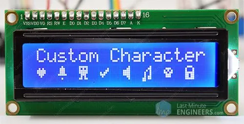
You will observe the following output on the LCD:
Code Explanation:
Once the library is imported and the LCD object is instantiated, custom character arrays are defined. Each array comprises 8 bytes, with each byte representing a row of a 5×8 LED matrix. In this code, eight custom characters have been created.
Let’s take the Heart[8] array as an example. You can observe how the bits (0s and 1s) form a heart shape. 0 turns off the pixel, while 1 turns it on.
byte Heart[8] = {
0b00000,
0b01010,
0b11111,
0b11111,
0b01110,
0b00100,
0b00000,
0b00000
};
Within the setup function, a custom character is generated using the createChar() function. This function requires two parameters. The first parameter is a number ranging from 0 to 7 to allocate one of the 8 supported custom characters. The second parameter is the name of the array.
lcd.createChar(0, Heart);
Subsequently, in the loop, to display the custom character, the write() function is employed, with the reserved character number passed as its argument.
lcd.setCursor(0, 1);
lcd.write(0);
Related article
- Mastering Interrupts and Timers: ESP8266 Development Guide
- ESP8266 Sensor Readings: Web Server Auto-Updates via Server-Sent Events
- Control IoT Devices: ESP8266 NodeMCU Async Web Server Tutorial
- Learn DC Motor Control with ESP32 and L298N Driver


