
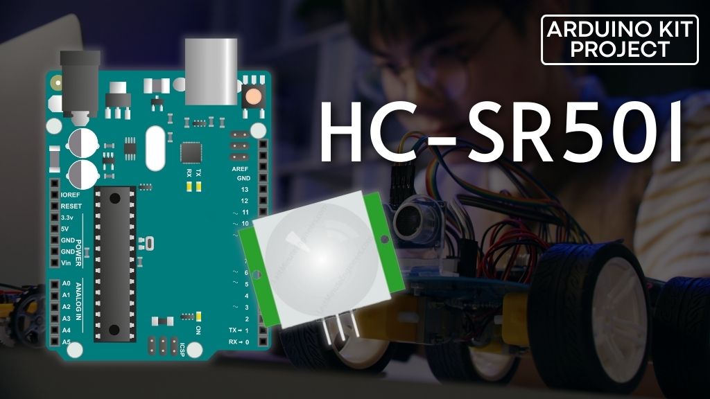
If you’re interested in building a home burglar alarm, a trail camera, or even animating Halloween props when trick-or-treaters arrive at your door, then you should definitely consider getting an HC-SR501 Passive Infrared (PIR) sensor.
The PIR sensor is designed to detect movement of people or animals within its range. It is commonly used in modern security systems, automatic light switches, garage door openers, and other applications that require motion detection.
Before diving into the details, let’s first understand how a PIR sensor actually works.
Parts Required
How does a PIR sensor work?
All objects, including the human body, emit heat energy in the form of infrared radiation when their temperature is above absolute zero (0 Kelvin / -273.15 °C). The amount of radiation emitted increases with the temperature of the object. However, since this radiation is in the infrared wavelength range, it is not visible to the human eye. The PIR sensor is specifically designed to detect and measure this infrared radiation.
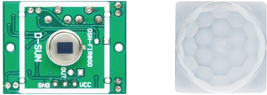
A PIR sensor consists of two main components:
- Pyroelectric sensor: This is the round metal component with a rectangular crystal in the center, as shown in the image.
- Fresnel lens: This special lens is responsible for focusing the infrared signals onto the pyroelectric sensor.
The Pyroelectric Sensor
A pyroelectric sensor consists of a window with two rectangular slots and is typically made of a material, such as coated silicon, that allows infrared radiation to pass through. Behind the window, there are two separate infrared sensor electrodes. One electrode generates a positive output, while the other generates a negative output.
These two electrodes are wired in a way that cancels out ambient infrared radiation. The focus is on detecting changes in infrared levels rather than the overall ambient levels. Thus, when one half of the sensor detects more or less infrared radiation than the other half, an output signal is generated.
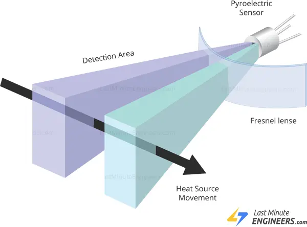
When there is no movement around the sensor, both slots detect the same amount of infrared radiation, resulting in a zero output signal.
However, when a warm body, like a human or an animal, passes by, it first intercepts one half of the sensor. This creates a positive differential change between the two halves. When the warm body moves away and intercepts the other half of the sensor, the opposite occurs, resulting in a negative differential change. By analyzing this voltage change, motion is detected.

The Fresnel Lens
Although it may not seem obvious, the Fresnel lens plays a crucial role in enhancing the range and field of view of the PIR sensor. Its slim and lightweight design, coupled with its excellent light-gathering capabilities, allows for the creation of compact yet powerful PIR sensors.
A Fresnel lens is composed of concentric grooves carved into plastic material. These grooves serve as individual refracting surfaces that converge parallel light rays towards a focal point. Consequently, a Fresnel lens, despite its reduced size, can focus light similar to a traditional optical lens.
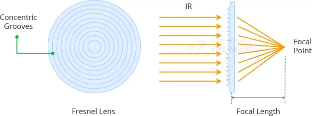
To expand the range and field of view of the PIR sensor, the lens is divided into multiple facet sections, with each section functioning as a separate Fresnel lens. These facets and sub-lenses generate a range of detection areas or zones that are interwoven with each other. This is why the centers of the lenses appear “inconsistent” in the provided image, as every other lens points to a different half of the PIR sensing element.
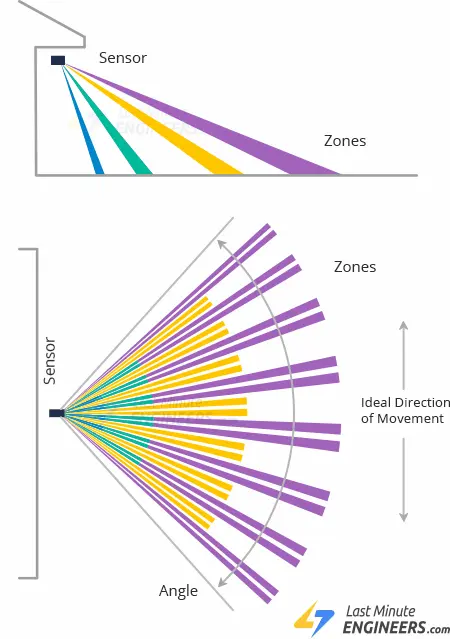
HC-SR501 PIR Sensor Hardware Overview
When it comes to detecting whether someone has entered or left an area in our Arduino projects, the HC-SR501 PIR sensor is an excellent choice. It offers low power consumption, affordability, easy interfacing, and is highly popular among hobbyists.
The PIR sensor itself is simple to use and requires minimal setup. Just provide power in the range of 5V to 12V and connect the ground. The sensor’s output goes HIGH when motion is detected and goes LOW when there is no motion (idle state).
By connecting this output to a microcontroller, you can trigger various actions in response to motion, such as turning lights ON/OFF, activating a fan, controlling a Halloween prop, or even capturing a picture of an intruder.
One of the key advantages is that the sensor consumes less than 2mA of current and can detect motion up to a distance of 7 meters (21 ft) with adjustable sensitivity.
BISS0001 PIR Controller
The core component of the module is the BISS0001, a passive infrared (PIR) controller IC. It is highly regarded for its excellent noise immunity, making it one of the most reliable PIR controllers in the market.
The BISS0001 IC receives the output signal from the pyroelectric sensor and performs minor processing on it to generate a digital output pulse.
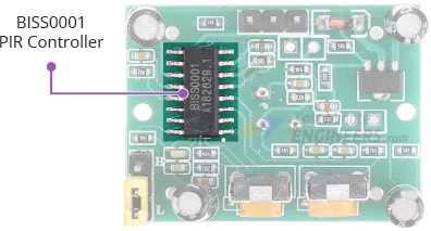
For detailed information about the BISS0001, you can refer to the datasheet. It provides comprehensive specifications and technical details about the controller.
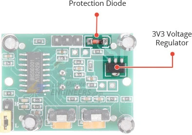
Power
The module is equipped with a 3.3V precision voltage regulator, allowing it to be powered by any DC voltage ranging from 4.5 to 12 volts, with 5V being the commonly used voltage.
To ensure safety, the module includes a protection diode that safeguards against reverse voltage and current. This means that even if you accidentally connect the power with incorrect polarity, the module will remain undamaged.
Sensitivity Adjustment
The PIR sensor module features a potentiometer located on the back for adjusting sensitivity.
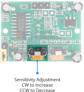
By using this potentiometer, you can set the maximum detection range of the sensor. The sensitivity can be adjusted within a range of approximately 3 meters to 7 meters (9 to 21 feet). It’s important to note that the actual range may vary based on the specific layout of your room or environment. To fine-tune the sensitivity, simply rotate the potentiometer clockwise to increase sensitivity and range, or rotate it counterclockwise to decrease sensitivity and range.
Time-Delay Adjustment
The PIR sensor module also includes a potentiometer on the back for adjusting the time delay.
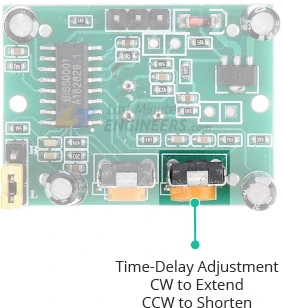
This potentiometer controls the duration for which the output remains HIGH after motion is detected. It can be adjusted within a range of approximately 1 second to 3 minutes. By rotating the potentiometer clockwise, you can increase the delay time, while rotating it counterclockwise will decrease the delay time.
Trigger Selection Jumper
The PIR sensor module provides two trigger modes that determine its behavior when motion is detected.
Single Trigger Mode: In this mode, continuous motion will result in a single trigger event.
Multiple Trigger Mode: In this mode, continuous motion will cause a series of trigger events.
The module includes a berg jumper (or a solder bridge jumper in some modules) that allows you to select one of the two modes:
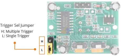
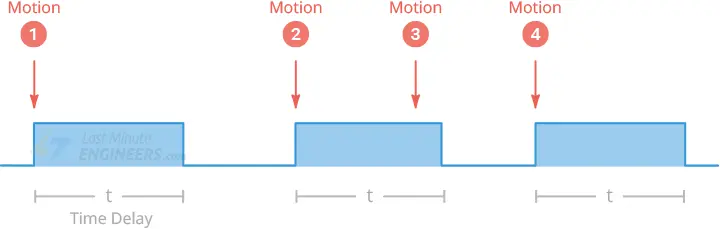
L – Selecting this mode enables the single trigger mode. When motion is detected, the output goes HIGH immediately and remains HIGH for a duration determined by the Time-Delay potentiometer. During this time, further motion detection is blocked until the output returns to LOW at the end of the time delay. If there is still motion present, the output will go HIGH again. Motion #3 in the provided image is completely ignored in this mode.
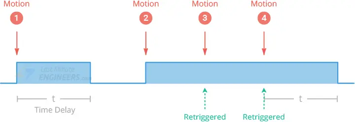
H – Selecting this mode activates the multiple trigger mode. When motion is detected, the output goes HIGH immediately and remains HIGH for a duration determined by the Time-Delay potentiometer. Unlike the single trigger mode, further motion detection is not blocked, so the time delay is reset each time motion is detected. The output only returns to LOW after a time delay once the motion ceases. Hence, this mode is referred to as the multiple trigger mode.
Optional Components – Thermistor and LDR
The HC SR501 Arduino module provides solder pads for two additional components, typically labeled as ‘RT’ and ‘RL’. Please note that on some boards, the label may be covered by the Fresnel lens on the opposite side of the components.
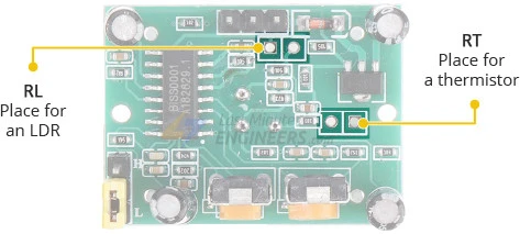
RT – This connection is designed for a thermistor or temperature-sensitive resistor. Adding a thermistor allows the HC-SR501 to be used in extreme temperature conditions, enhancing the accuracy of the motion detection system.
RL – This connection is intended for a Light Dependent Resistor (LDR) or Photoresistor. By adding an LDR, the HC-SR501 can function in low light conditions or darkness. This feature is particularly useful for creating motion-sensitive lighting systems.
These additional components can be directly soldered onto the module or connected to remote locations using wires and connectors, providing flexibility in their installation.
Technical Specifications
Here are the specifications:
| Operating Voltage | 4.5 – 20V (typically 5V) |
| Maximum Current Draw | < 2mA |
| Time Delay | ~ 1 sec to 3 min |
| Detection Distance | 3 – 7 meters (9 – 21 feet) |
| Detection Angle | 120 degrees (typically) |
HC-SR501 PIR Sensor Pinout
The HC-SR501 PIR sensor features a 3-pin connector. The markings on the pins may be obscured by the Fresnel lens, so please refer to the accompanying image for the pinout details.
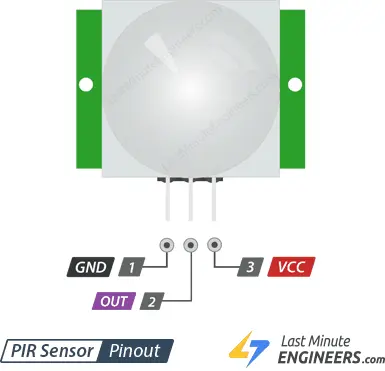
VCC: This pin is used to supply power to the sensor. You can connect a voltage input ranging from 5V to 12V to this pin, although the commonly used voltage is 5V.
Output: The output pin provides a 3.3V TTL logic output. It goes HIGH when motion is detected and goes LOW when no motion is detected.
GND: This pin is the ground connection for the sensor, providing the reference for the electrical circuit.
Using PIR Sensor as a standalone unit
The HC-SR501 PIR sensor is highly versatile and can be effectively used as a standalone sensor. Its functionality can be enhanced further by connecting it to a microcontroller such as Arduino.
In this experiment, we will showcase the usefulness of the HC SR501 arduino as a standalone sensor.
The wiring for this experiment is simple. Connect the sensor’s VCC and GND to a power source, and connect a small red LED to the output pin through a 220Ω current limiting resistor. That’s it!
Now, when the PIR sensor detects motion, the output pin will go “HIGH,” illuminating the LED.
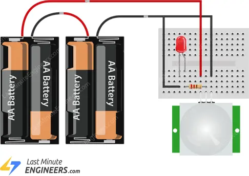
It’s important to note that after powering up the circuit, you should wait for 30-60 seconds to allow the PIR sensor to adapt to the infrared energy in the room. During this time, the LED may blink intermittently. Once the LED is completely off, you can move around in front of the sensor or wave your hand, observing the LED light up accordingly.
If you wish to control an external device based on motion, you can directly connect the PIR output to a relay module. This allows you to turn something ON/OFF based on the detected motion.
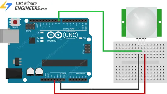
Wiring a PIR Sensor to an Arduino
Connecting the PIR sensor to an Arduino is a straightforward process. Follow these steps to establish the connection:
- Power the PIR sensor with 5V and connect the ground (GND) pin of the sensor to the Arduino’s ground (GND).
- The PIR sensor acts as a digital output, so connect its output pin to one of the Arduino’s digital pins. In this example, we’ll use digital pin #8, but you can choose any available digital pin.
To ensure the proper functioning of the HC-SR501 sensor, follow these additional steps:
- Set the jumper on the PIR sensor module to the H position, indicating the Multiple Trigger Mode.
- Adjust the Time-Delay potentiometer counterclockwise to set the time delay to at least 3 seconds. Rotate the potentiometer as far as it will go in the counterclockwise direction.
- Set the sensitivity potentiometer to your desired position. If you’re unsure, set it to the midpoint for a balanced sensitivity level.
Here is a table summarizing the pin connections:
| PIR Sensor | Arduino |
|---|---|
| VCC | 5V |
| GND | GND |
| Output | Digital Pin 8 |
Refer to the image below for a visual representation of how to connect the HC-SR501 PIR sensor to the Arduino.
Now that you have successfully established the wiring, you are ready to upload code to the Arduino and start utilizing the PIR sensor’s functionality.
Arduino Example Code
The code is very simple. It basically just keeps track of whether the input to pin #8 is HIGH or LOW.
int ledPin = 13;                // choose the pin for the LED
int inputPin = 8;               // choose the input pin (for PIR sensor)
int pirState = LOW;             // we start, assuming no motion detected
int val = 0;                    // variable for reading the pin status

void setup() {
  pinMode(ledPin, OUTPUT);      // declare LED as output
  pinMode(inputPin, INPUT);     // declare sensor as input

  Serial.begin(9600);
}

void loop(){
  val = digitalRead(inputPin);  // read input value

  if (val == HIGH)	// check if the input is HIGH
  {
    digitalWrite(ledPin, HIGH);  // turn LED ON

    if (pirState == LOW)
	{
      Serial.println("Motion detected!");	// print on output change
      pirState = HIGH;
    }
  }
  else
  {
    digitalWrite(ledPin, LOW); // turn LED OFF

    if (pirState == HIGH)
	{
      Serial.println("Motion ended!");	// print on output change
      pirState = LOW;
    }
  }
}
With the sensor pointing up, swipe your hand over the sensor. You should see a “Motion Detected” message printed on the serial terminal.
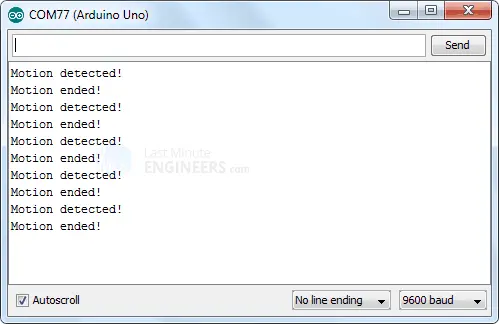
Things to consider before designing PIR based applications
When designing applications using the HC-SR501 PIR sensor, it is important to consider the following delay periods:
Lockout Time:
After the sensor output goes LOW, it remains LOW for approximately 2 seconds, during which motion sensing is locked out.
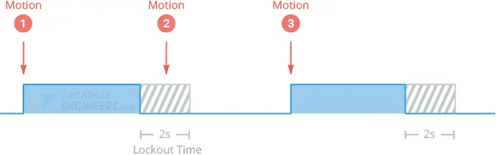
For example, if you have set a time delay of 4 seconds and selected the ‘L’ jumper mode, the output will go HIGH for 4 seconds when motion is detected. After that, it will remain LOW for about 2 seconds, ignoring any motion during this period.
Power On Delay:
- Like most PIR sensors, the HC SR501 arduino requires an initialization period of approximately 30 to 60 seconds after being powered on.
- During this time, the sensor calibrates itself to the environment by learning the ambient infrared signature.
- It is important to ignore any triggers during this calibration period, as false triggers may occur.
- Additionally, avoid excessive movement in front of the sensor during self-calibration, as it can interfere with the calibration process.
By considering these delay periods, you can ensure proper functionality and avoid false triggers when designing applications using the HC-SR501 PIR sensor.
Related article
- Understanding Accelerometers: Interface ADXL335 with Arduino
- Arduino Soil NPK Sensor: Maximizing Plant Nutrition
- Step-by-Step: Connecting Reed Switch to Arduino
- Track Heart Rate: A Guide to Pulse Sensor and Arduino Integration
- Using TMP36 Temperature Sensor: Arduino Interfacing Guide


