
Have you ever pondered how your smartphone determines its orientation? It’s among the most remarkable functionalities of modern smartphones. Each one contains a miniature component known as an accelerometer within its circuitry. This component detects shifts in the device’s orientation, enabling your smartphone to seamlessly switch between portrait and landscape modes.
Accelerometers find extensive application in various fields requiring motion and tilt sensing capabilities, including mobile devices, gaming consoles, disk drive protection mechanisms, image stabilization systems, as well as sports and health monitoring devices.
Let’s delve into what accelerometers are, their functionalities, and their operational principles.
Parts Required
| Component Name | Buy Now |
| Arduino Uno REV3 | Amazon |
| Adafruit ADXL335-5V Ready Triple-axis Accelerometer | Amazon |
How Does an Accelerometer Function?
To grasp the operation of accelerometers, envision a sphere enclosed within a three-dimensional cube.

In a scenario where the cube exists in outer space, devoid of gravitational effects, the sphere will remain suspended at the cube’s center.
Now, envisage each face of the cube representing a distinct axis.
If we suddenly shift the cube to the left with an acceleration of 1g (where 1g equals 9.8 m/s², representing the gravitational force), the sphere will inevitably collide with face X. By measuring the force exerted by the sphere on face X, we can derive an output value of 1g along the X axis.

Consider what occurs when we position the cube on Earth. The sphere will promptly descend onto face Z, exerting a force of 1g, as illustrated in the diagram:

In this instance, although the cube remains stationary, we still register a 1g measurement along the Z axis. This arises because gravity, functioning as a form of acceleration, pulls the sphere downward with a force of 1g.
While this model doesn’t precisely replicate the construction of a real-world accelerometer sensor, it aids in comprehending why accelerometer output signals are typically expressed in ±g, or why an accelerometer records 1g along the z-axis when stationary, or what accelerometer readings to anticipate at varying orientations.
In practical terms, accelerometers rely on Micro-Electro-Mechanical Systems (MEMS fabrication technology). Hence, let’s explore the functioning of a MEMS accelerometer.
How Does a MEMS Accelerometer Work?
A MEMS (Micro-Electro-Mechanical System) accelerometer comprises a micro-machined framework constructed atop a silicon wafer.
This framework is supported by polysilicon springs, enabling deflection when subjected to acceleration along the X, Y, and/or Z axes.
As deflection occurs, the capacitance between fixed plates and plates linked to the suspended framework alters. This variation in capacitance correlates with the acceleration along the respective axis.
The sensor interprets this capacitance shift, transforming it into an analog output voltage.
ADXL335 Module Hardware Overview
At the heart of this module lies a compact, energy-efficient, and low-noise triple-axis MEMS accelerometer manufactured by Analog Devices – the ADXL335. This device is capable of not only detecting static acceleration induced by gravity but also dynamic acceleration resulting from movement, impact, or vibration.
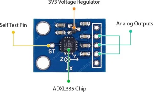
This module, designed to fit onto a breadboard seamlessly, exposes each pin of the ADXL335 through a 6-pin, 0.1′′ pitch header. These pins include three analog outputs for measuring acceleration along the X, Y, and Z axes, two power supply pins, and a self-test pin.
Power
The ADXL335 operates within a voltage range of 1.8V to 3.6VDC (typically 3.3V). However, the inclusion of an onboard 3.3V regulator renders it suitable for interfacing with 5V microcontrollers like the Arduino.
Under normal operating conditions, the sensor consumes a mere 350μA of current.
Measurement Range
With a full sensing range of ±3g, the ADXL335 can accurately measure and represent accelerations within this range. If subjected to accelerations exceeding ±3g, the accelerometer will not malfunction, but its output may saturate.
The absolute maximum acceleration the ADXL335 can withstand is 10,000g. Accelerations beyond this threshold may cause the device to malfunction.
Ratiometric Output
The output of the ADXL335 is ratiometric, meaning the output voltage increases linearly with acceleration across its range. Consequently, the output voltage corresponds to specific acceleration levels: 0g yields half of the 3.3V supply voltage (1.65V), -3g corresponds to 0V, and +3g corresponds to 3.3V, with linear scaling in between.
Technical Specifications
Here are the specifications.
| Operating Voltage | 1.8V – 3.6V |
| Operating Current | 350μA (typical) |
| Sensing Range | ±3g (Full Scale) |
| Temperature Range | −40 to +85°C |
| Sensing axis | 3 axis |
| Sensitivity | 270 to 330mV/g (Ratiometric) |
| Shock Resistance | Up to 10,000g |
| Dimension | 4mm x 4mm x 1.45mm |
For more information, please refer to the datasheet below.
ADXL335 Accelerometer Pinout
Before diving into the connection setup and example code, let’s examine its Pinout.
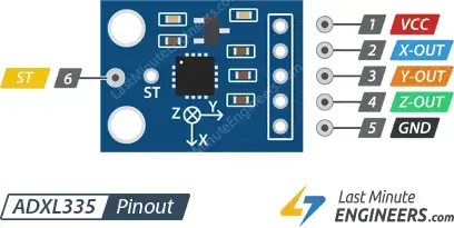
- VCC: This pin supplies power to the module. Connect it to the 5V output of your Arduino.
- X-Out: This pin outputs an analog voltage that corresponds to the acceleration along the X axis.
- Y-Out: This pin outputs an analog voltage that corresponds to the acceleration along the Y axis.
- Z-Out: This pin outputs an analog voltage that corresponds to the acceleration along the Z axis.
- GND: This is the ground pin.
- ST (Self-Test): This pin controls the self-test feature, allowing you to assess the sensor’s functionality in the final application. Further details on this feature are provided at the conclusion of the tutorial.
Wiring an ADXL335 Accelerometer to an Arduino
Now that we understand how the ADXL335 accelerometer operates, let’s proceed to connect it to our Arduino.
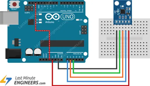
The connections are straightforward. Begin by placing the accelerometer on the breadboard. Connect the VCC pin to the Arduino’s 5V pin and the GND pin to the Arduino’s ground pin. Then, connect the X, Y, and Z outputs to the Arduino’s analog pins A0, A1, and A2 respectively.
For precise results, we need to adjust the analog reference (AREF) voltage on the Arduino. This can be achieved by linking the Arduino’s 3.3V pin to the AREF pin.
The following diagram illustrates the wiring configuration.
Arduino Example Code – Reading the ADXL335 accelerometer
The code is straightforward. It merely showcases the calibrated sensor output for each axis on the serial interface. Before delving into the specifics, give the sketch a try.
const int xInput = A0;
const int yInput = A1;
const int zInput = A2;

// initialize minimum and maximum Raw Ranges for each axis
int RawMin = 0;
int RawMax = 1023;

// Take multiple samples to reduce noise
const int sampleSize = 10;

void setup()
{
	analogReference(EXTERNAL);
	Serial.begin(9600);
}

void loop()
{
	//Read raw values
	int xRaw = ReadAxis(xInput);
	int yRaw = ReadAxis(yInput);
	int zRaw = ReadAxis(zInput);

	// Convert raw values to 'milli-Gs"
	long xScaled = map(xRaw, RawMin, RawMax, -3000, 3000);
	long yScaled = map(yRaw, RawMin, RawMax, -3000, 3000);
	long zScaled = map(zRaw, RawMin, RawMax, -3000, 3000);

	// re-scale to fractional Gs
	float xAccel = xScaled / 1000.0;
	float yAccel = yScaled / 1000.0;
	float zAccel = zScaled / 1000.0;

	Serial.print("X, Y, Z  :: ");
	Serial.print(xRaw);
	Serial.print(", ");
	Serial.print(yRaw);
	Serial.print(", ");
	Serial.print(zRaw);
	Serial.print(" :: ");
	Serial.print(xAccel,0);
	Serial.print("G, ");
	Serial.print(yAccel,0);
	Serial.print("G, ");
	Serial.print(zAccel,0);
	Serial.println("G");

	delay(200);
}

// Take samples and return the average
int ReadAxis(int axisPin)
{
	long reading = 0;
	analogRead(axisPin);
	delay(1);
	for (int i = 0; i < sampleSize; i++)
	{
	reading += analogRead(axisPin);
	}
	return reading/sampleSize;
}
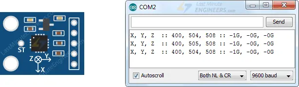
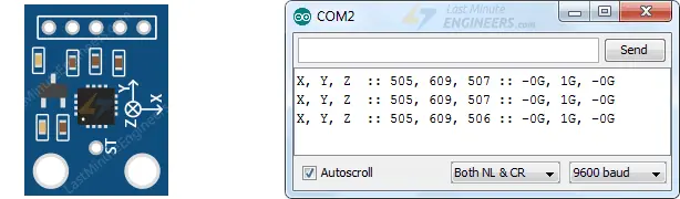
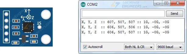
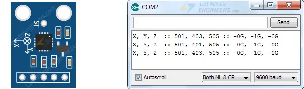
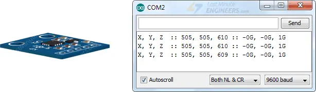
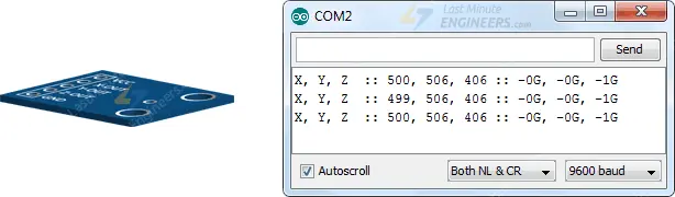
Below are images displaying the accelerometer readings at different orientations.
Code Explanation:
The sketch commences by defining the Arduino’s analog input pins to which the sensor’s X, Y, and Z output pins are linked.
const int xInput = A0;
const int yInput = A1;
const int zInput = A2;
Following this, two variables, RawMin and RawMax, are established. Given that the Arduino employs a 10-bit ADC (210 = 1024), it will map the output voltages of the ADXL335, ranging from 0 to 3.3 volts, into integer values spanning from 0 to 1023. Hence, RawMin is set to 0, and RawMax is set to 1023.
// initialize minimum and maximum Raw Ranges for each axis
int RawMin = 0;
int RawMax = 1023;
The sampleSize variable indicates the number of samples the Arduino should capture during each conversion. In this instance, sampleSize is set to 10 to enhance result accuracy.
// Take multiple samples to reduce noise
const int sampleSize = 10;
Within the setup section, we first configure the analog reference to EXTERNAL by invoking analogReference(EXTERNAL). Subsequently, we initiate serial communication with the PC.
analogReference(EXTERNAL);
Serial.begin(9600);
In the loop section, we retrieve analog outputs from the sensor every 200ms. Notably, instead of utilizing the analogRead() function, we employ the ReadAxis() custom function, which acquires ten ADC conversion samples and yields their average.
//Read raw values
int xRaw = ReadAxis(xInput);
int yRaw = ReadAxis(yInput);
int zRaw = ReadAxis(zInput);
Converting ADXL335 Output to Acceleration(g)
The subsequent code excerpt represents the pivotal aspect of the program. It delineates the mapping and conversion of analog output voltages from the sensor to gravitational acceleration (g).
This mapping is facilitated by the IDE’s built-in map() function. Upon invoking map(xRaw, RawMin, RawMax, -3000, 3000), RawMin is mapped to -3000, RawMax to 3000, and intermediary values are mapped accordingly.
- If the sensor yields 0 volts on the x-axis (xRaw=0), the map() function will return -3000, representing -3g.
- For an output of 1.65 volts on the x-axis (xRaw=511), map() will return 0, indicating 0g.
- If the sensor produces 3.3 volts on the x-axis (xRaw=1023), map() will return 3000, signifying +3g.
The concept of Ratiometric becomes clearer now as the output voltage rises linearly with acceleration across the range.
// Convert raw values to 'milli-Gs"
long xScaled = map(xRaw, RawMin, RawMax, -3000, 3000);
long yScaled = map(yRaw, RawMin, RawMax, -3000, 3000);
long zScaled = map(zRaw, RawMin, RawMax, -3000, 3000);
Ultimately, the sensor’s output is downscaled to fractional g’s by dividing it by 1000 and then displayed on the serial monitor.
// re-scale to fractional Gs
float xAccel = xScaled / 1000.0;
float yAccel = yScaled / 1000.0;
float zAccel = zScaled / 1000.0;

Serial.print("X, Y, Z  :: ");
Serial.print(xRaw);
Serial.print(", ");
Serial.print(yRaw);
Serial.print(", ");
Serial.print(zRaw);
Serial.print(" :: ");
Serial.print(xAccel,0);
Serial.print("G, ");
Serial.print(yAccel,0);
Serial.print("G, ");
Serial.print(zAccel,0);
Serial.println("G");
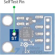
ADXL335 Self-Test Feature
The ADXL335 Accelerometer features a self-test capability designed to assess the sensor’s functionality within the final application. This functionality is controlled by the ST (self-test) pin on the module.
When the ST pin is linked to 3.3V, an electrostatic force acts upon the accelerometer beam internally. Consequently, the beam undergoes movement, enabling users to ascertain the accelerometer’s operational status.
The anticipated alterations in output are as follows:
- -1.08 g (-325 mV) on the X-axis
- +1.08 g (+325 mV) on the Y-axis
- +1.83 g (+550 mV) on the Z-axis
During normal operation, the ST pin can be left unconnected or connected to GND.
Related article
- Arduino Soil NPK Sensor: Maximizing Plant Nutrition
- Step-by-Step: Connecting Reed Switch to Arduino
- Track Heart Rate: A Guide to Pulse Sensor and Arduino Integration
- Using TMP36 Temperature Sensor: Arduino Interfacing Guide
- Arduino Water Quality Testing: Utilizing the TDS Sensor


