

Within this tutorial, you will gain insights into employing an Arduino board alongside a TDS meter (Total Dissolved Solids). The TDS meter serves as an indicator for the cumulative dissolved solids, encompassing salts, minerals, and metals, within a solution. This metric proves valuable for assessing water quality and facilitating comparisons among water derived from various origins. A primary utility of the TDS meter lies in monitoring the quality of water in aquariums.
Our focus will be on utilizing the TDS meter from Keystudio, and we will present a straightforward example demonstrating how to measure TDS in parts per million (ppm) units using the Arduino IDE.
Presenting the TDS Meter
A TDS meter gauges the quantity of total dissolved solids such as salts, minerals, and metals in water. With the escalation of dissolved solids, the water’s conductivity increases, enabling the calculation of total dissolved solids in parts per million (ppm) or milligrams per liter (mg/L).
While this serves as a reliable indicator for monitoring water quality, it’s crucial to note that it doesn’t assess contaminants in the water. Therefore, relying solely on this metric is insufficient for determining the suitability of water for consumption.
The utility of a TDS meter extends to monitoring water quality in various applications, including pools, aquariums, fish tanks, hydroponics, and water purifiers.
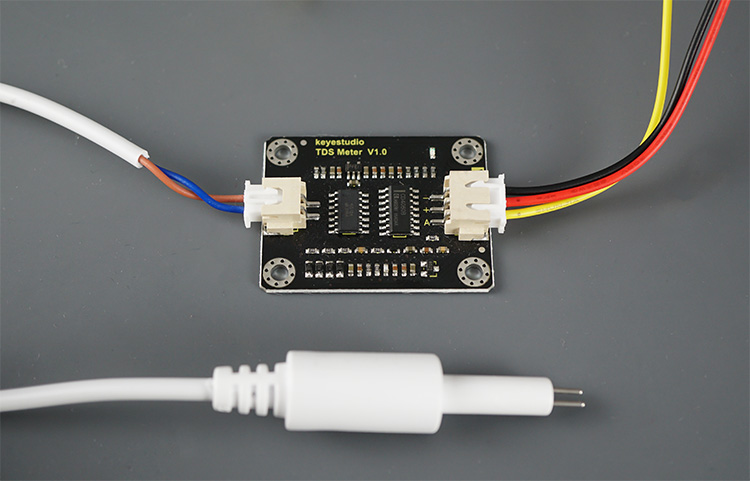
In this guide, we’ll utilize the Keystudio TDS meter, which includes an interface module and an electrode probe (refer to the image above).
For more detailed information about the TDS meter, we recommend consulting the official documentation.
Characteristics and Specifications
This guide pertains to the TDS Meter V1.0 by Keystudio. Here are the sensor details:
TDS Meter:
- Input Voltage: DC 3.3 ~ 5.5V
- Output Voltage: 0 ~ 2.3V
- Working Current: 3 ~ 6mA
- TDS Measurement Range: 0 ~ 1000ppm
- TDS Measurement Accuracy: ± 10% F.S. (25 ℃)
- Module Interface: XH2.54-3P
- Electrode Interface: XH2.54-2P
TDS Probe:
- Number of Needles: 2
- Total Length: 60cm
- Connection Interface: XH2.54-2P
- Color: White
- Waterproof Probe
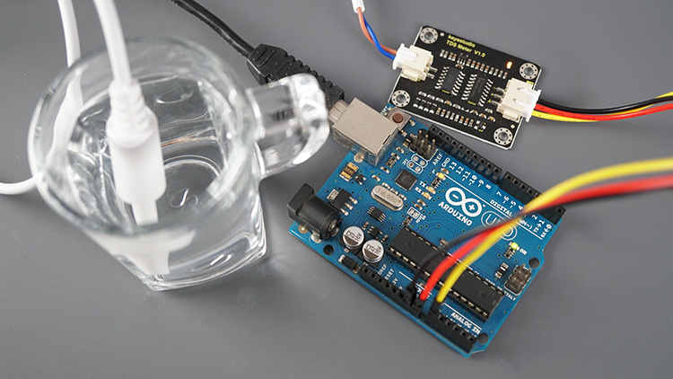
Interfacing the TDS Meter with the Arduino
The TDS meter outputs an analog signal that can be measured using the Arduino analog pins (A0 to A5).
Wire the sensor as in the following table:
| TDS Sensor | Arduino |
| GND | GND |
| VCC | 3.3V |
| Data | A0 (or any other Arduino analog pin) |
Parts Required
| Component Name | Buy Now |
| Arduino Uno REV3 | Amazon |
| TDS (Total Dissolved Solids) Meter Sensor | Amazon |
| Breadboard | Amazon |
| BOJACK 1000 Pcs 25 Values Resistor Kit 1 Ohm-1M Ohm with 5% 1/4W | Amazon |
Reading TDS (Water Quality) with Arduino Code
As mentioned earlier, the sensor generates an analog signal that can be translated into TDS in ppm. We are utilizing the code provided in the sensor documentation with some modifications.
For more accurate results, it is advisable to calibrate your sensor against a solution with a known TDS value. However, calibration may not be necessary if your concern is more qualitative than specific TDS values.
Upload the following code to your Arduino.
// Original source code: https://wiki.keyestudio.com/KS0429_keyestudio_TDS_Meter_V1.0#Test_Code
// Project details: https://RandomNerdTutorials.com/arduino-tds-water-quality-sensor/

#define TdsSensorPin A0
#define VREF 5.0              // analog reference voltage(Volt) of the ADC
#define SCOUNT  30            // sum of sample point

int analogBuffer[SCOUNT];     // store the analog value in the array, read from ADC
int analogBufferTemp[SCOUNT];
int analogBufferIndex = 0;
int copyIndex = 0;

float averageVoltage = 0;
float tdsValue = 0;
float temperature = 16;       // current temperature for compensation

// median filtering algorithm
int getMedianNum(int bArray[], int iFilterLen){
  int bTab[iFilterLen];
  for (byte i = 0; i<iFilterLen; i++)
  bTab[i] = bArray[i];
  int i, j, bTemp;
  for (j = 0; j < iFilterLen - 1; j++) {
    for (i = 0; i < iFilterLen - j - 1; i++) {
      if (bTab[i] > bTab[i + 1]) {
        bTemp = bTab[i];
        bTab[i] = bTab[i + 1];
        bTab[i + 1] = bTemp;
      }
    }
  }
  if ((iFilterLen & 1) > 0){
    bTemp = bTab[(iFilterLen - 1) / 2];
  }
  else {
    bTemp = (bTab[iFilterLen / 2] + bTab[iFilterLen / 2 - 1]) / 2;
  }
  return bTemp;
}

void setup(){
  Serial.begin(115200);
  pinMode(TdsSensorPin,INPUT);
}

void loop(){
  static unsigned long analogSampleTimepoint = millis();
  if(millis()-analogSampleTimepoint > 40U){     //every 40 milliseconds,read the analog value from the ADC
    analogSampleTimepoint = millis();
    analogBuffer[analogBufferIndex] = analogRead(TdsSensorPin);    //read the analog value and store into the buffer
    analogBufferIndex++;
    if(analogBufferIndex == SCOUNT){
      analogBufferIndex = 0;
    }
  }

  static unsigned long printTimepoint = millis();
  if(millis()-printTimepoint > 800U){
    printTimepoint = millis();
    for(copyIndex=0; copyIndex<SCOUNT; copyIndex++){
      analogBufferTemp[copyIndex] = analogBuffer[copyIndex];

      // read the analog value more stable by the median filtering algorithm, and convert to voltage value
      averageVoltage = getMedianNum(analogBufferTemp,SCOUNT) * (float)VREF / 1024.0;

      //temperature compensation formula: fFinalResult(25^C) = fFinalResult(current)/(1.0+0.02*(fTP-25.0));
      float compensationCoefficient = 1.0+0.02*(temperature-25.0);
      //temperature compensation
      float compensationVoltage=averageVoltage/compensationCoefficient;

      //convert voltage value to tds value
      tdsValue=(133.42*compensationVoltage*compensationVoltage*compensationVoltage - 255.86*compensationVoltage*compensationVoltage + 857.39*compensationVoltage)*0.5;

      //Serial.print("voltage:");
      //Serial.print(averageVoltage,2);
      //Serial.print("V   ");
      Serial.print("TDS Value:");
      Serial.print(tdsValue,0);
      Serial.println("ppm");
    }
  }
}
How the Code Operates
Let’s delve into the functionality of the code. Alternatively, you can proceed directly to the Demonstration section.
The TdsSensorPin variable designates the GPIO pin for obtaining readings. For the ESP8266, which has only one analog pin, A0 is used.
#define TdsSensorPin A0
Next, specify the analog voltage reference for the ADC, which is 5V for Arduino.
#define VREF 5.0 // analog reference voltage(Volt) of the ADC
Before acquiring a measurement value, a median filtering algorithm is applied to ensure stability. The SCOUNT variable signifies the number of samples to filter before obtaining an actual value.
#define SCOUNT 30 // sum of sample point
Arrays and index variables are set up to store readings.
int analogBuffer[SCOUNT];     // store the analog value in the array, read from ADC
int analogBufferTemp[SCOUNT];
int analogBufferIndex = 0;
int copyIndex = 0;
Initialize the averageVoltage and tsdValue variables as float variables.
float averageVoltage = 0;
float tdsValue = 0;
The temperature variable holds the current temperature value, influencing the readings. An algorithm compensates for temperature fluctuations. In this instance, the reference temperature is 25ºC, but you can adjust it based on your environment. For more precision, a temperature sensor can be added to obtain the actual temperature during sensor readings.
float temperature = 25; // current temperature for compensation
The getMedianNum function is employed to obtain a stable TDS value from an array of readings.
// median filtering algorithm
int getMedianNum(int bArray[], int iFilterLen){
  int bTab[iFilterLen];
  for (byte i = 0; i<iFilterLen; i++)
  bTab[i] = bArray[i];
  int i, j, bTemp;
  for (j = 0; j < iFilterLen - 1; j++) {
    for (i = 0; i < iFilterLen - j - 1; i++) {
      if (bTab[i] > bTab[i + 1]) {
        bTemp = bTab[i];
        bTab[i] = bTab[i + 1];
        bTab[i + 1] = bTemp;
      }
    }
  }
  if ((iFilterLen & 1) > 0){
    bTemp = bTab[(iFilterLen - 1) / 2];
  }
  else {
    bTemp = (bTab[iFilterLen / 2] + bTab[iFilterLen / 2 - 1]) / 2;
  }
  return bTemp;
}
In the setup(), initialize the Serial Monitor with a baud rate of 115200 and set the TDS sensor pin as an input.
Serial.begin(115200);
Set the TDS sensor pin as an input.
pinMode(TdsSensorPin,INPUT);
In the loop(), get new TDS readings every 40 milliseconds and save them in the buffer:
static unsigned long analogSampleTimepoint = millis();
if(millis()-analogSampleTimepoint > 40U){     //every 40 milliseconds,read the analog value from the ADC
  analogSampleTimepoint = millis();
  analogBuffer[analogBufferIndex] = analogRead(TdsSensorPin);    //read the analog value and store into the buffer
  analogBufferIndex++;
  if(analogBufferIndex == SCOUNT){
    analogBufferIndex = 0;
  }
}
Then, every 800 milliseconds, it gets the latest readings and gets the average voltage by using the filtering algorithm created before:
static unsigned long printTimepoint = millis();
if(millis()-printTimepoint > 800U){
  printTimepoint = millis();
  for(copyIndex=0; copyIndex<SCOUNT; copyIndex++){
    analogBufferTemp[copyIndex] = analogBuffer[copyIndex];

    // read the analog value more stable by the median filtering algorithm, and convert to voltage value
    averageVoltage = getMedianNum(analogBufferTemp,SCOUNT) * (float)VREF / 1024.0;
Then, it calculates a temperature compensation coefficient and calculates the TDS value taking that value into account:
//temperature compensation formula: fFinalResult(25^C) = fFinalResult(current)/(1.0+0.02*(fTP-25.0));
float compensationCoefficient = 1.0+0.02*(temperature-25.0);
//temperature compensation
float compensationVoltage=averageVoltage/compensationCoefficient;

//convert voltage value to tds value
tdsValue=(133.42*compensationVoltage*compensationVoltage*compensationVoltage- 255.86*compensationVoltage*compensationVoltage + 857.39*compensationVoltage)*0.5;
Finally, it prints the TDS value in ppm:
Serial.print("TDS Value:");
Serial.print(tdsValue,0);
Serial.println("ppm");
Demonstration
Upon copying the code to the Arduino IDE, proceed to upload it to your board. Ensure you select the correct board in Tools > Board and the appropriate COM port in Tools > Port.
Once uploaded, open the Serial Monitor with a baud rate of 115200.
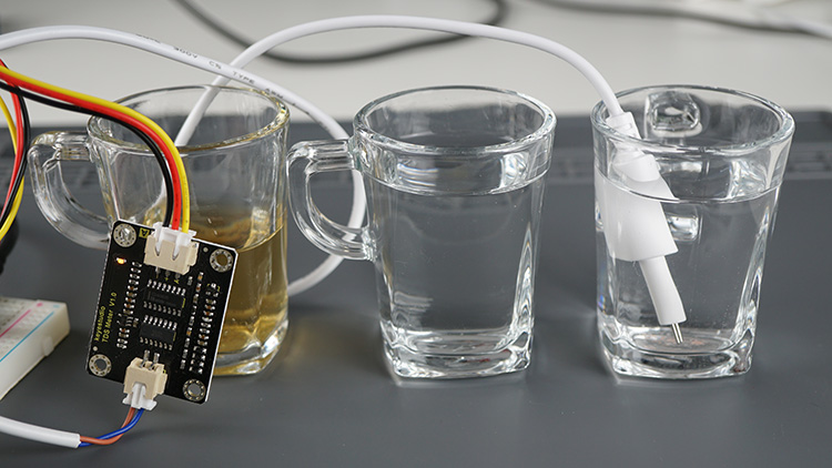
If the probe is not submerged, the display will show a value close to 0. Place the probe in a solution to check its TDS. Experiment with tap water and add some salt to observe an increase in values.
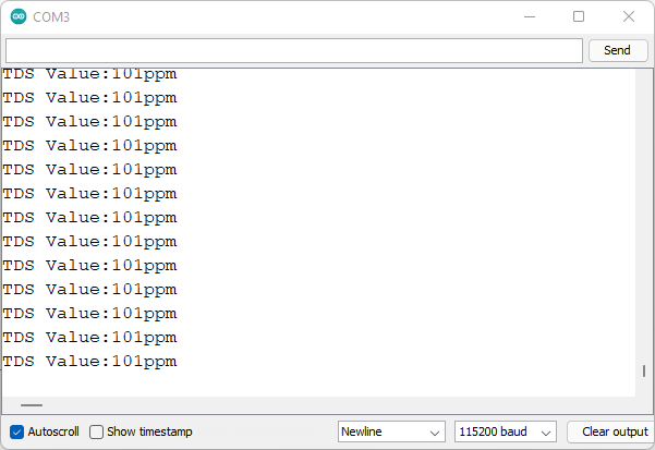
In my household, I measured the TDS value for tap water, obtaining a reading of approximately 100ppm, indicative of good drinking water quality.
Testing with tea resulted in a TDS value of around 230ppm, which appears reasonable.
Lastly, measuring the TDS value of bottled water yielded a reading of about 25ppm (consistent with results using an ESP8266).
Wrapping Up
In summary, a TDS meter serves to measure the total dissolved solids in a solution, offering an indicator of water quality and allowing for water characterization. The meter provides the TDS value in ppm (parts per million—mg/L). While the TDS value finds various applications, it should not be solely relied upon to determine the potability of water.
An exemplary use of such a sensor is in monitoring aquarium water quality, where it can be paired with a waterproof DS18B20 temperature sensor for comprehensive fish tank monitoring.
Explore our tutorials for other well-known sensors compatible with the Arduino board that might interest you:
- Interface Rain Sensor with Arduino: Step-by-Step Tutorial
- Interface Water Level Sensor with Arduino: Step-by-Step Tutorial
- How to Interface Capacitive Soil Moisture Sensor with Arduino


my analogRead(A0) gives the output of around 30 consistently for tap water when the sensor is powered via 3.3v pin of arduino. When I add some salt it it its around 34 consistently. Is my sensor ok?
my sensor is this one “https://ebhoot.in/shop-2/sensors/water-moisture-sensors/analog-tds-sensor-module-for-arduino-and-microcontroller/”