

If you’ve experienced a water heater explosion or have worked on submersible electronics, you understand the significance of detecting water presence.
The Water Level Sensor we’re discussing here serves precisely that purpose. It enables you to measure water levels, monitor sump pits, detect rainfall, and identify leaks.
Now, let’s delve into the specifics of this sensor.
Hardware Overview
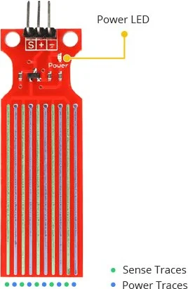
The Water Level Sensor features ten exposed copper traces, with five dedicated to power and the other five to sensing. These traces are arranged in an interlaced pattern, with each sense trace positioned between two power traces.
Under normal conditions, the power and sense traces are not connected. However, when the sensor comes into contact with water, these traces bridge together.
The board is equipped with a Power LED that illuminates when the sensor is powered up.
How Does a Water Level Sensor Work?
The water level sensor operates based on a straightforward principle.
The power and sense traces of the sensor act as a variable resistor, similar to a potentiometer. The resistance of this variable resistor changes depending on the extent to which it is exposed to water.
The resistance of the sensor varies in inverse proportion to the depth of immersion in water:
- When the sensor is more immersed in water, there is better conductivity, resulting in lower resistance.
- Conversely, when the sensor is less immersed in water, conductivity decreases, leading to higher resistance.
Based on the resistance, the sensor produces an output voltage that is directly proportional to the resistance. By measuring this voltage, the water level can be determined.
Water Level Sensor Pinout
The water level sensor is easy to use and requires three pins for connection.
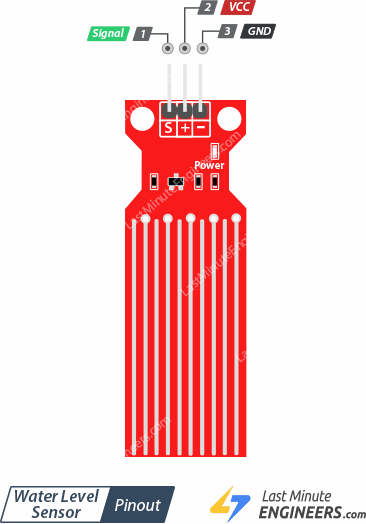
S (Signal): This is the analog output pin of the sensor, which should be connected to one of the analog inputs on your Arduino.
+(VCC): This pin supplies power to the sensor. It is recommended to power the sensor with a voltage between 3.3V and 5V. Please note that the analog output value will vary based on the supplied voltage.
-(GND): This is the ground pin of the sensor, which should be connected to the ground (GND) pin on your Arduino.
Wiring a Water Level Sensor to an Arduino
Let’s connect the water level sensor to the Arduino.
- Connect the + (VCC) pin on the sensor module to the 5V pin on the Arduino.
- Connect the – (GND) pin on the sensor module to the ground (GND) pin on the Arduino.
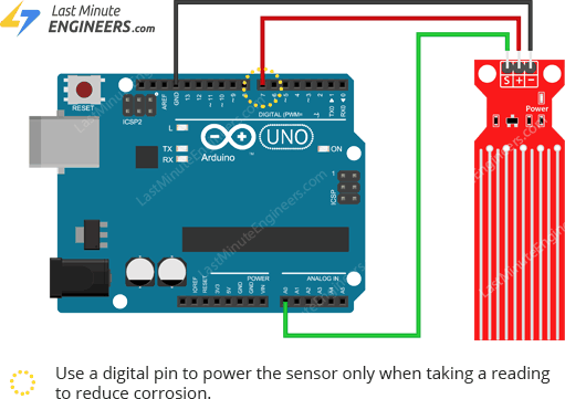
It is recommended to turn on the sensor only when taking readings to prolong its lifespan. You can achieve this by connecting the sensor’s power pin to a digital pin on the Arduino and controlling its state. In this case, we will connect the + (VCC) pin to digital pin #7 on the Arduino.
Finally, connect the S (Signal) pin on the sensor module to the A0 ADC pin on the Arduino.
Refer to the image below for the wiring configuration.
Basic Arduino Example
Once you have assembled the circuit, upload the following code to your Arduino.
// Sensor pins
#define sensorPower 7
#define sensorPin A0

// Value for storing water level
int val = 0;

void setup() {
	// Set D7 as an OUTPUT
	pinMode(sensorPower, OUTPUT);

	// Set to LOW so no power flows through the sensor
	digitalWrite(sensorPower, LOW);

	Serial.begin(9600);
}

void loop() {
	//get the reading from the function below and print it
	int level = readSensor();

	Serial.print("Water level: ");
	Serial.println(level);

	delay(1000);
}

//This is a function used to get the reading
int readSensor() {
	digitalWrite(sensorPower, HIGH);	// Turn the sensor ON
	delay(10);							// wait 10 milliseconds
	val = analogRead(sensorPin);		// Read the analog value form sensor
	digitalWrite(sensorPower, LOW);		// Turn the sensor OFF
	return val;							// send current reading
}
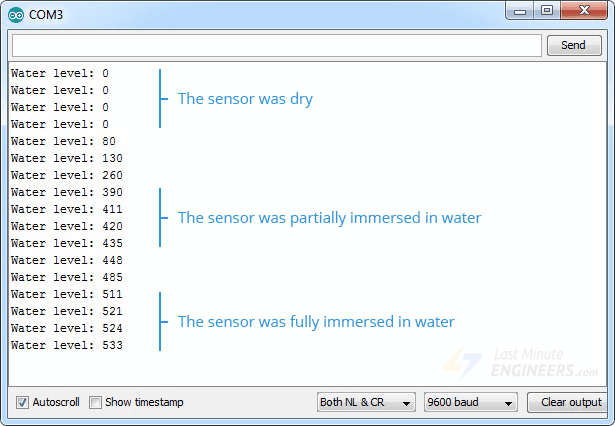
After uploading the sketch, open the Serial Monitor window in the Arduino IDE to observe the output. When the sensor is dry, it will display a value of 0. As the sensor is immersed in water, the output will gradually increase.
Code Explanation:
The code provided starts by defining the Arduino pins to which the sensor’s + (VCC) and S (signal) pins are connected.
#define sensorPower 7
#define sensorPin A0
A variable named “val” is declared to store the current water level.
int val = 0;
In the Setup section, the sensor’s power connection is configured as an output, and it is initially set to low to keep the sensor off. Serial communication is also initiated.
pinMode(sensorPower, OUTPUT);
digitalWrite(sensorPower, LOW);
Serial.begin(9600);
Inside the loop section, the custom function "readSensor()" is called every one second, and the result is printed.
Serial.print("Water level: ");
Serial.println(readSensor());
delay(1000);
The "readSensor()" function simply turns on the sensor, waits for 10 milliseconds, reads the analog value from the sensor, turns it off, and returns the analog value.
int readSensor() {
	digitalWrite(sensorPower, HIGH);
	delay(10);
	val = analogRead(sensorPin);
	digitalWrite(sensorPower, LOW);
	return val;
}
Finding the threshold values
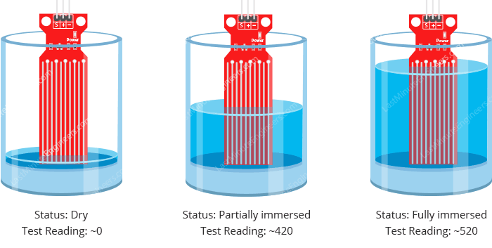
To determine the water level, you need to record the sensor output values when it is completely dry, partially immersed, and fully immersed in water.
Simply run the provided sketch and take note of the readings.
Please be aware that the sensitivity of your sensor may vary depending on the type of water used. Pure water itself is not conductive; it is the minerals and impurities in the water that contribute to conductivity.
Upon running the sketch, you should observe readings similar to the following:
- When the sensor is dry: 0
- When the sensor is partially immersed in water: around 420
- When the sensor is fully immersed in water: around 520
This process may involve some trial and error. Once you have obtained the readings, you can utilize them as thresholds to trigger specific actions based on the water level.
Arduino Project – Water Level Indicator
For our next project, we will create a simple water level indicator that utilizes LEDs to display the water level.
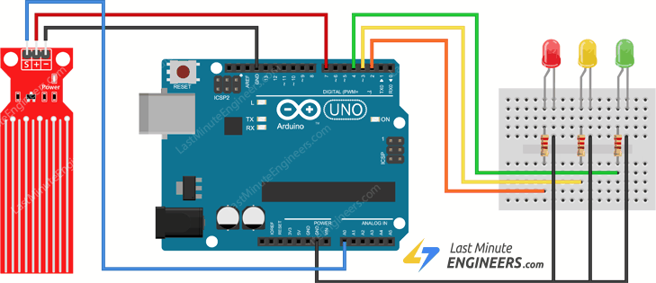
Wiring
We will utilize the circuit from the previous example and add LEDs to enhance the indicator.
Connect three LEDs to digital pins #2, #3, and #4, ensuring to use 220 ohm resistors.
Follow the wiring diagram below to connect your circuit:
Parts Required
| Component Name | Buy Now |
| Arduino Uno REV3 | Amazon |
| Rain Water Water Level Sensor | Amazon |
| Breadboard | Amazon |
| BOJACK 1000 Pcs 25 Values Resistor Kit 1 Ohm-1M Ohm with 5% 1/4W | Amazon |
| 5mm LED Light Diodes | Amazon |
Arduino Code
Once the circuit is assembled, upload the following sketch to your Arduino.
The sketch includes the definition of two variables: lowerThreshold and upperThreshold, which represent the thresholds for water level indication.
If the sensor output falls below the lower threshold, the red LED will illuminate. If it exceeds the upper threshold, the green LED will light up. For water levels between the two thresholds, the yellow LED will be activated.
/* Change these values based on your calibration values */
int lowerThreshold = 420;
int upperThreshold = 520;

// Sensor pins
#define sensorPower 7
#define sensorPin A0

// Value for storing water level
int val = 0;

// Declare pins to which LEDs are connected
int redLED = 2;
int yellowLED = 3;
int greenLED = 4;

void setup() {
	Serial.begin(9600);
	pinMode(sensorPower, OUTPUT);
	digitalWrite(sensorPower, LOW);

	// Set LED pins as an OUTPUT
	pinMode(redLED, OUTPUT);
	pinMode(yellowLED, OUTPUT);
	pinMode(greenLED, OUTPUT);

	// Initially turn off all LEDs
	digitalWrite(redLED, LOW);
	digitalWrite(yellowLED, LOW);
	digitalWrite(greenLED, LOW);
}

void loop() {
	int level = readSensor();

	if (level == 0) {
		Serial.println("Water Level: Empty");
		digitalWrite(redLED, LOW);
		digitalWrite(yellowLED, LOW);
		digitalWrite(greenLED, LOW);
	}
	else if (level > 0 && level <= lowerThreshold) {
		Serial.println("Water Level: Low");
		digitalWrite(redLED, HIGH);
		digitalWrite(yellowLED, LOW);
		digitalWrite(greenLED, LOW);
	}
	else if (level > lowerThreshold && level <= upperThreshold) {
		Serial.println("Water Level: Medium");
		digitalWrite(redLED, LOW);
		digitalWrite(yellowLED, HIGH);
		digitalWrite(greenLED, LOW);
	}
	else if (level > upperThreshold) {
		Serial.println("Water Level: High");
		digitalWrite(redLED, LOW);
		digitalWrite(yellowLED, LOW);
		digitalWrite(greenLED, HIGH);
	}
	delay(1000);
}

//This is a function used to get the reading
int readSensor() {
	digitalWrite(sensorPower, HIGH);
	delay(10);
	val = analogRead(sensorPin);
	digitalWrite(sensorPower, LOW);
	return val;
}
Related article
- Arduino Soil NPK Sensor: Maximizing Plant Nutrition
- Soil Moisture Sensor: How It Works and Arduino Interface Guide
- How to Interface Capacitive Soil Moisture Sensor with Arduino
- Interface Rain Sensor with Arduino: Step-by-Step Tutorial


