
If you’re interested in creating a smart garden, a key component you’ll need is a Soil Moisture Sensor. This sensor allows you to monitor the moisture level of the soil and automate the watering process, ensuring plants receive the right amount of water at the right time. By implementing this system, you can prevent issues like over-watering or under-watering, leading to healthier and thriving plants.
How Does a Soil Moisture Sensor Work?
The operation of a soil moisture sensor is relatively simple. The sensor consists of a fork-shaped probe with two exposed conductors that function as a variable resistor, similar to a potentiometer. The resistance of the sensor changes in response to the moisture content of the soil. Here’s how it works:
- When the soil contains more water, it exhibits better conductivity, resulting in lower resistance.
- Conversely, when the soil is drier, its conductivity decreases, leading to higher resistance.
Based on the varying resistance, the sensor generates an output voltage that corresponds to the soil’s moisture level. By measuring this voltage, we can determine the relative moisture content of the soil.
Hardware Overview
A typical soil moisture sensor consists of two main components: the probe and the module.
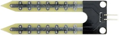
The Probe:
The probe is a fork-shaped structure with two exposed conductors. It is inserted into the soil or the desired area for measuring moisture content. Acting as a variable resistor, the probe’s resistance changes in response to the moisture level in the soil.
Module:
The sensor also includes an electronic module that connects the probe to an Arduino or other microcontroller. The module performs several functions:
Analog Output (AO): It generates an output voltage based on the resistance of the probe. This analog signal can be read by the microcontroller.
Digital Output (DO): The same signal is processed by an LM393 High Precision Comparator, which converts it into a digital signal. The module provides a Digital Output (DO) pin that indicates the moisture level as a binary value (LOW or HIGH).
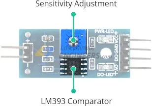
Sensitivity Adjustment: The module incorporates a potentiometer that allows you to adjust the sensitivity of the digital output (DO). By setting a threshold, you can define a moisture level at which the output switches from HIGH to LOW or vice versa.
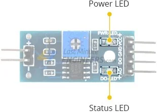
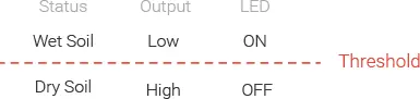
Indicator LEDs: The module is equipped with two LEDs. The Power LED indicates that the module is powered on, while the Status LED lights up when the soil moisture level surpasses the threshold value set by the sensitivity adjustment.
This configuration is particularly useful for triggering actions based on specific moisture thresholds. For instance, when the soil moisture level exceeds a predetermined threshold, you can activate a relay to initiate plant watering.
Soil Moisture Sensor Pinout
The soil moisture sensor is straightforward to use, requiring only four pins for connection.
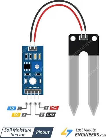
AO (Analog Output): It generates an analog output voltage that is proportional to the soil moisture level. A higher moisture level corresponds to a higher voltage, while a lower moisture level corresponds to a lower voltage.
DO (Digital Output): This pin indicates whether the soil moisture level is within the set limit. When the moisture level exceeds the threshold value (set by the potentiometer), the DO pin becomes LOW; otherwise, it is HIGH.
VCC: This pin supplies power to the sensor. It is recommended to provide a power supply between 3.3V and 5V. Please note that the analog output voltage will vary depending on the voltage supplied to the sensor.
GND: This pin is the ground connection for the sensor.
Parts Required
Experiment 1 – Measuring Soil Moisture using Analog Output (A0)
In our initial experiment, we will utilize the analog output to estimate the soil moisture level.
Wiring
Let’s connect the soil moisture sensor to the Arduino.
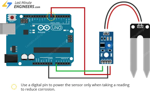
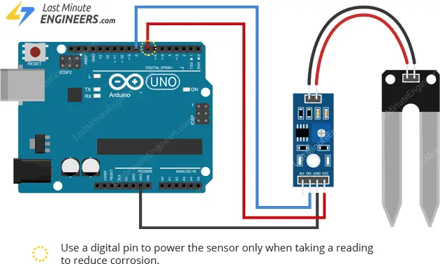
To begin, provide power to the sensor. You can achieve this by connecting the VCC pin of the module to the Arduino’s 5V pin.
However, it is worth noting that these sensors have a shorter lifespan due to constant exposure to moisture. Additionally, leaving the sensor powered while buried in soil can accelerate corrosion.
To mitigate this, it is recommended to only turn on the sensor when taking readings.
An easy approach is to connect the sensor’s power pin to a digital pin on the Arduino and control its state (HIGH or LOW) as necessary. The module’s power consumption (with both LEDs illuminated) is approximately 8 mA, making it suitable to power from a digital pin. Hence, we will connect the VCC pin to digital pin #7 on the Arduino.
Finally, connect the A0 pin of the sensor to the Arduino’s A0 ADC pin.
Refer to the image below for the wiring configuration.
Finding the threshold values
To determine the threshold values for soil moisture, record the sensor output readings when the soil is as dry as possible and when it is fully saturated.
Execute the provided sketch below and obtain your readings.
// Sensor pins
#define sensorPower 7
#define sensorPin A0

void setup() {
	pinMode(sensorPower, OUTPUT);

	// Initially keep the sensor OFF
	digitalWrite(sensorPower, LOW);

	Serial.begin(9600);
}

void loop() {
	//get the reading from the function below and print it
	Serial.print("Analog output: ");
	Serial.println(readSensor());

	delay(1000);
}

//  This function returns the analog soil moisture measurement
int readSensor() {
	digitalWrite(sensorPower, HIGH);	// Turn the sensor ON
	delay(10);							// Allow power to settle
	int val = analogRead(sensorPin);	// Read the analog value form sensor
	digitalWrite(sensorPower, LOW);		// Turn the sensor OFF
	return val;							// Return analog moisture value
}
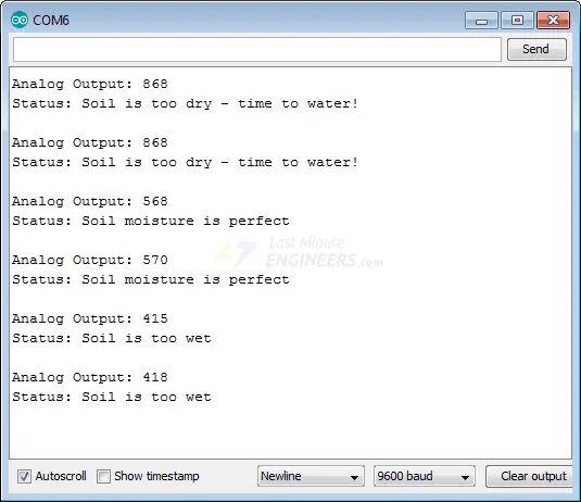
Upon running the sketch, expect to see readings similar to the following:
- When the soil is dry (around 850)
- When the soil is completely saturated (around 400)
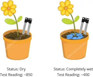
This process may involve some experimentation and adjustment. Once you have the readings, you can utilize them as thresholds to trigger specific actions.
Arduino Code
The sketch below estimates the level of soil moisture using the following threshold values:
- < 500 is too wet
- 500-750 is the target range
- > 750 is dry enough to be watered
/* Change these values based on your calibration values */
#define soilWet 500   // Define max value we consider soil 'wet'
#define soilDry 750   // Define min value we consider soil 'dry'

// Sensor pins
#define sensorPower 7
#define sensorPin A0

void setup() {
	pinMode(sensorPower, OUTPUT);

	// Initially keep the sensor OFF
	digitalWrite(sensorPower, LOW);

	Serial.begin(9600);
}

void loop() {
	//get the reading from the function below and print it
	int moisture = readSensor();
	Serial.print("Analog Output: ");
	Serial.println(moisture);

	// Determine status of our soil
	if (moisture < soilWet) {
		Serial.println("Status: Soil is too wet");
	} else if (moisture >= soilWet && moisture < soilDry) {
		Serial.println("Status: Soil moisture is perfect");
	} else {
		Serial.println("Status: Soil is too dry - time to water!");
	}

	delay(1000);	// Take a reading every second for testing
					// Normally you should take reading perhaps once or twice a day
	Serial.println();
}

//  This function returns the analog soil moisture measurement
int readSensor() {
	digitalWrite(sensorPower, HIGH);	// Turn the sensor ON
	delay(10);							// Allow power to settle
	int val = analogRead(sensorPin);	// Read the analog value form sensor
	digitalWrite(sensorPower, LOW);		// Turn the sensor OFF
	return val;							// Return analog moisture value
}
If everything is fine, you should see something similar on the serial monitor.
Experiment 2 – Measuring Soil Moisture using Digital Output (D0)
In our second experiment, we will utilize digital output to determine if the soil moisture level falls within acceptable limits.
Wiring
Reuse the circuit from the previous experiment. Disconnect the connection to the ADC pin and connect the D0 pin on the module to digital pin #8 on the Arduino.
Refer to the provided image for the wiring setup.
Setting the threshold
The module is equipped with a built-in potentiometer that allows you to set the moisture level threshold. This threshold determines when the module outputs LOW and the status LED illuminates.
To set the threshold:
- Insert the probe into the soil when your plant requires watering.
- Rotate the potentiometer clockwise until the Status LED turns on.
- Gradually rotate the potentiometer counterclockwise until the LED turns off.
That’s all you need to do. Your module is now ready for use.
Arduino Code
Upload the following sketch to your Arduino.
// Sensor pins
#define sensorPower 7
#define sensorPin 8

void setup() {
	pinMode(sensorPower, OUTPUT);

	// Initially keep the sensor OFF
	digitalWrite(sensorPower, LOW);

	Serial.begin(9600);
}

void loop() {
	//get the reading from the function below and print it
	int val = readSensor();
	Serial.print("Digital Output: ");
	Serial.println(val);

	// Determine status of our soil moisture situation
	if (val) {
		Serial.println("Status: Soil is too dry - time to water!");
	} else {
		Serial.println("Status: Soil moisture is perfect");
	}

	delay(1000);	// Take a reading every second for testing
					// Normally you shoul take reading perhaps every 12 hours
	Serial.println();
}

//  This function returns the analog soil moisture measurement
int readSensor() {
	digitalWrite(sensorPower, HIGH);  // Turn the sensor ON
	delay(10);              // Allow power to settle
	int val = digitalRead(sensorPin); // Read the analog value form sensor
	digitalWrite(sensorPower, LOW);   // Turn the sensor OFF
	return val;             // Return analog moisture value
}
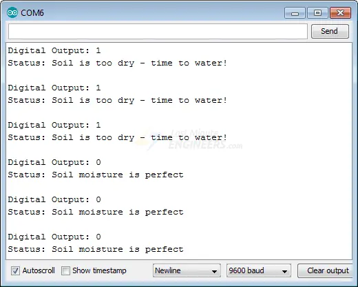
You should observe similar output on the serial monitor.
Related article
- Arduino Soil NPK Sensor: Maximizing Plant Nutrition
- Step-by-Step Guide: HC-SR501 PIR Sensor Working Principles and Arduino Integration
- Understanding the Operation of HC-SR04 Ultrasonic Sensor and Connecting it to Arduino
- MQ3 Alcohol Sensor: How It Works & Arduino Integration Guide
- How to Interface Capacitive Soil Moisture Sensor with Arduino


