

Within this manual, you will acquire knowledge on employing a TDS Sensor ESP8266 NodeMCU board. The TDS meter gauges the aggregate of dissolved solids, such as salts, minerals, and metals, within a solution. This metric serves as a means to assess water quality and facilitate comparisons between water obtained from various origins. A primary application of the TDS meter is the monitoring of aquarium water quality.
We will utilize the TDS meter from keystudio and provide a straightforward illustration demonstrating how to measure TDS in parts per million (ppm) using the Arduino IDE.
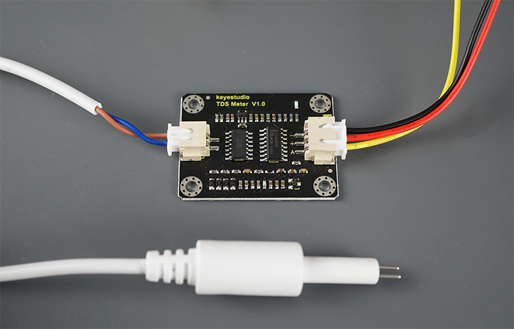
Introducing the TDS Meter
A TDS meter is designed to quantify the total dissolved solids, including salts, minerals, and metals, present in water. As the quantity of dissolved solids in water rises, so does the water’s conductivity, enabling us to compute the total dissolved solids in parts per million (ppm) or milligrams per liter (mg/L).
While this serves as a valuable gauge for monitoring water quality, it’s crucial to note that it doesn’t assess contaminants in the water. Therefore, relying solely on this indicator is insufficient to determine the suitability of water for consumption.
TDS meters find utility in various applications such as monitoring water quality in pools, aquariums, fish tanks, hydroponic systems, water purifiers, and more.
In this tutorial, we will employ the keystudio TDS meter, which includes an interface module and an electrode probe (as depicted in the image above).
For additional details about the TDS meter, we recommend consulting the official documentation.
Features and Specifications
This guide pertains to the TDS Meter V1.0 by keystudio. Below are the specifications for the sensor:
TDS Meter:
- Input Voltage: DC 3.3 ~ 5.5V
- Output Voltage: 0 ~ 2.3V
- Working Current: 3 ~ 6mA
- TDS Measurement Range: 0 ~ 1000ppm
- TDS Measurement Accuracy: ± 10% F.S. (25 ℃)
- Module Interface: XH2.54-3P
- Electrode Interface: XH2.54-2P
TDS Probe:
- Number of Needles: 2
- Total Length: 60cm
- Connection Interface: XH2.54-2P
- Color: White
- Waterproof Probe
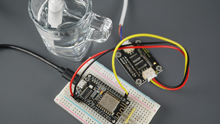
Interfacing the TDS Meter with the ESP8266
The TDS meter outputs an analog signal that can be measured using the ESP8266 analog pin A0.
Wire the sensor as in the following table:
| TDS Sensor | ESP8266 |
| GND | GND |
| VCC | 3.3V |
| Data | A0 |
Parts Required
| Component Name | Buy Now |
| ESP8266 NodeMCU CP2102 | Amazon |
| TDS (Total Dissolved Solids) Meter Sensor | Amazon |
| Breadboard | Amazon |
| BOJACK 1000 Pcs 25 Values Resistor Kit 1 Ohm-1M Ohm with 5% 1/4W | Amazon |
ESP8266 TDS (Water Quality) Reading – Code
As mentioned earlier, the sensor generates an analog signal that can be translated into TDS in parts per million (ppm). We are utilizing the code outlined in the sensor documentation with certain adjustments.
For enhanced precision, it is advisable to calibrate your sensor against a solution with a known TDS value. Nevertheless, calibration may not be necessary if your focus is on a qualitative assessment of TDS rather than specific values.
Proceed to upload the subsequent code to your ESP8266.
#define TdsSensorPin A0
#define VREF 3.3              // analog reference voltage(Volt) of the ADC
#define SCOUNT  30            // sum of sample point

int analogBuffer[SCOUNT];     // store the analog value in the array, read from ADC
int analogBufferTemp[SCOUNT];
int analogBufferIndex = 0;
int copyIndex = 0;

float averageVoltage = 0;
float tdsValue = 0;
float temperature = 23;       // current temperature for compensation

// median filtering algorithm
int getMedianNum(int bArray[], int iFilterLen){
  int bTab[iFilterLen];
  for (byte i = 0; i<iFilterLen; i++)
  bTab[i] = bArray[i];
  int i, j, bTemp;
  for (j = 0; j < iFilterLen - 1; j++) {
    for (i = 0; i < iFilterLen - j - 1; i++) {
      if (bTab[i] > bTab[i + 1]) {
        bTemp = bTab[i];
        bTab[i] = bTab[i + 1];
        bTab[i + 1] = bTemp;
      }
    }
  }
  if ((iFilterLen & 1) > 0){
    bTemp = bTab[(iFilterLen - 1) / 2];
  }
  else {
    bTemp = (bTab[iFilterLen / 2] + bTab[iFilterLen / 2 - 1]) / 2;
  }
  return bTemp;
}

void setup(){
  Serial.begin(115200);
  pinMode(TdsSensorPin,INPUT);
}

void loop(){
  static unsigned long analogSampleTimepoint = millis();
  if(millis()-analogSampleTimepoint > 40U){     //every 40 milliseconds,read the analog value from the ADC
    analogSampleTimepoint = millis();
    analogBuffer[analogBufferIndex] = analogRead(TdsSensorPin);    //read the analog value and store into the buffer
    analogBufferIndex++;
    if(analogBufferIndex == SCOUNT){
      analogBufferIndex = 0;
    }
  }

  static unsigned long printTimepoint = millis();
  if(millis()-printTimepoint > 800U){
    printTimepoint = millis();
    for(copyIndex=0; copyIndex<SCOUNT; copyIndex++){
      analogBufferTemp[copyIndex] = analogBuffer[copyIndex];

      // read the analog value more stable by the median filtering algorithm, and convert to voltage value
      averageVoltage = getMedianNum(analogBufferTemp,SCOUNT) * (float)VREF / 1024.0;

      //temperature compensation formula: fFinalResult(25^C) = fFinalResult(current)/(1.0+0.02*(fTP-25.0));
      float compensationCoefficient = 1.0+0.02*(temperature-25.0);
      //temperature compensation
      float compensationVoltage=averageVoltage/compensationCoefficient;

      //convert voltage value to tds value
      tdsValue=(133.42*compensationVoltage*compensationVoltage*compensationVoltage - 255.86*compensationVoltage*compensationVoltage + 857.39*compensationVoltage)*0.5;

      //Serial.print("voltage:");
      //Serial.print(averageVoltage,2);
      //Serial.print("V   ");
      Serial.print("TDS Value:");
      Serial.print(tdsValue,0);
      Serial.println("ppm");
    }
  }
}
How the Code Works
Let’s take a quick look at the code. You can also skip right away to the Demonstration section.
The TdsSensorPin variable saves the GPIO where you want to get the readings. The ESP8266 only has one analog pin, A0.
#define TdsSensorPin A0
Then, insert the analog voltage reference for the ADC. For the ESP8266 is 3.3V, for an Arduino, for example, it is 5V.
#define VREF 3.3 // analog reference voltage(Volt) of the ADC
Before getting a measurement value, we’ll apply a median filtering algorithm to get a more stable value. The SCOUNT variable refers to the number of samples we’ll filter before getting an actual value.
#define SCOUNT 30 // sum of sample point
Then, we need some arrays to store the readings as well as some index variables that will allow us to go through the arrays.
int analogBuffer[SCOUNT];     // store the analog value in the array, read from ADC
int analogBufferTemp[SCOUNT];
int analogBufferIndex = 0;
int copyIndex = 0;
Initialize the averageVoltage variable and tsdValue as float variables.
float averageVoltage = 0;
float tdsValue = 0;
The temperature variable saves the current temperature value. The temperature influences the readings, so there is an algorithm that compensates for fluctuations in temperature. In this example, the reference temperature is 25ºC, but you can change it depending on your environment. For more accurate results, you can add a temperature sensor and get the actual temperature at the time of reading the sensor.
float temperature = 25; // current temperature for compensation
The following function will be used to get a stable TDS value from an array of readings.
// median filtering algorithm
int getMedianNum(int bArray[], int iFilterLen){
  int bTab[iFilterLen];
  for (byte i = 0; i<iFilterLen; i++)
  bTab[i] = bArray[i];
  int i, j, bTemp;
  for (j = 0; j < iFilterLen - 1; j++) {
    for (i = 0; i < iFilterLen - j - 1; i++) {
      if (bTab[i] > bTab[i + 1]) {
        bTemp = bTab[i];
        bTab[i] = bTab[i + 1];
        bTab[i + 1] = bTemp;
      }
    }
  }
  if ((iFilterLen & 1) > 0){
    bTemp = bTab[(iFilterLen - 1) / 2];
  }
  else {
    bTemp = (bTab[iFilterLen / 2] + bTab[iFilterLen / 2 - 1]) / 2;
  }
  return bTemp;
}
In the setup(), initialize the Serial Monitor at a baud rate of 115200.
Serial.begin(115200);
Set the TDS sensor pin as an input.
pinMode(TdsSensorPin,INPUT);
In the loop(), get new TDS readings every 40 milliseconds and save them in the buffer:
static unsigned long analogSampleTimepoint = millis();
if(millis()-analogSampleTimepoint > 40U){     //every 40 milliseconds,read the analog value from the ADC
  analogSampleTimepoint = millis();
  analogBuffer[analogBufferIndex] = analogRead(TdsSensorPin);    //read the analog value and store into the buffer
  analogBufferIndex++;
  if(analogBufferIndex == SCOUNT){
    analogBufferIndex = 0;
  }
}
Then, every 800 milliseconds, it gets the latest readings and gets the average voltage by using the filtering algorithm created before:
static unsigned long printTimepoint = millis();
if(millis()-printTimepoint > 800U){
  printTimepoint = millis();
  for(copyIndex=0; copyIndex<SCOUNT; copyIndex++){
    analogBufferTemp[copyIndex] = analogBuffer[copyIndex];

    // read the analog value more stable by the median filtering algorithm, and convert to voltage value
    averageVoltage = getMedianNum(analogBufferTemp,SCOUNT) * (float)VREF / 1024.0;
Then, it calculates a temperature compensation coefficient and calculates the TDS Sensor ESP8266 value taking that value into account:
//temperature compensation formula: fFinalResult(25^C) = fFinalResult(current)/(1.0+0.02*(fTP-25.0));
float compensationCoefficient = 1.0+0.02*(temperature-25.0);
//temperature compensation
float compensationVoltage=averageVoltage/compensationCoefficient;

//convert voltage value to tds value
tdsValue=(133.42*compensationVoltage*compensationVoltage*compensationVoltage - 255.86*compensationVoltage*compensationVoltage + 857.39*compensationVoltage)*0.5;
Finally, it prints the TDS value in ppm:
Serial.print("TDS Value:");
Serial.print(tdsValue,0);
Serial.println("ppm");
Presentation
Once you have copied the code into the Arduino IDE, proceed to upload it to your board. Remember to choose the correct board under Tools > Board and the appropriate COM port under Tools > Port.
After the upload, launch the Serial Monitor with a baud rate of 115200 and press the ESP8266 RST button to initiate the code.
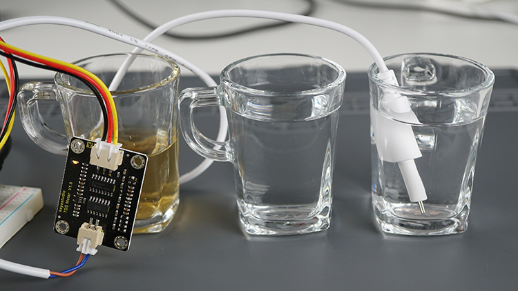
If the probe is not submerged, it will display a value of approximately 0. Place the probe in a solution to assess its TDS. You can experiment with tap water and introduce some salt to observe an increase in values.
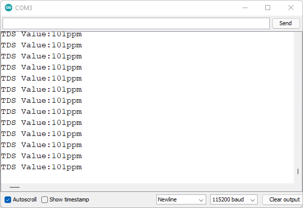
I conducted a TDS measurement for tap water in my residence, yielding a value of around 100ppm, indicating good drinking water quality.
Testing with tea resulted in a TDS value of approximately 230ppm, a reasonably expected outcome.
Lastly, I measured the TDS value of bottled water, registering around 25ppm. Do you have one of these sensors? What values did you obtain for bottled water?
Wrapping Up
A TDS meter is capable of gauging the total dissolved solids in a solution, serving as an indicator for water quality and enabling characterization of the water. The meter provides the TDS value in parts per million (ppm or mg/L). While the TDS value finds various applications, it should not be solely relied upon to determine the potability of water.
An excellent application for this sensor type is as an aquarium water quality monitor. You can pair this sensor with a waterproof DS18B20 temperature sensor to oversee conditions in your fish tank, for instance.
Are you intrigued by the idea of an Aquarium Water Quality Monitor? I am contemplating the development of a web application to oversee and regulate aquarium temperature and water quality. Additionally, it could control a pump through an output pin of the ESP8266. What are your thoughts?
We trust you found this tutorial valuable. We also offer tutorials for other popular sensors that might pique your interest:
- DIY Digital Scale: ESP8266 NodeMCU & Load Cell + HX711 Amplifier Setup
- ESP32 Web Server Tutorial: PWM LED Brightness Control Slider
- DHT11/DHT22 Interface with ESP8266 NodeMCU Web Server: Step-by-Step
- Complete Guide: ESP8266 Over The Air (OTA) Programming with Arduino IDE


