

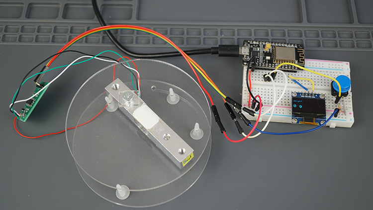
In this guide, you’ll be taken step by step through the process of creating a scale using the ESP8266 NodeMCU along with a load cell and the arduino HX711 amplifier. Initially, you’ll become familiar with the necessary wiring connections needed to link the load cell arduino and HX711 amplifier to the ESP8266 for constructing the scale. After that, we’ll detail the calibration process for the scale and present a simple example for determining the weight of objects. Furthermore, we’ll enhance the tutorial by integrating a display to present measurements and adding a button to perform taring on the scale.
Introducing Load Cells
Load cells have a primary function of converting force into a measurable electrical signal. This signal’s magnitude changes proportionally with the applied force. There are several types of load cells available, including strain gauges, pneumatic, and hydraulic variants. In this guide, our focus will be on strain gauge load cells.
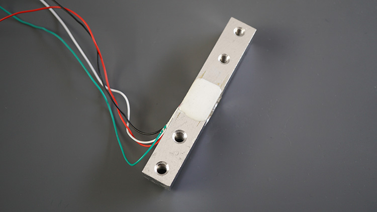
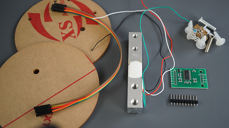
Strain gauge load cell arduino are constructed with a metal bar equipped with attached strain gauges (located beneath the white adhesive in the above image). Strain gauges, acting as electrical sensors, gauge the force or strain experienced by an object. When an external force impacts an object, like the metal bar in this instance, the resistance of the strain gauges shifts due to the object’s deformation. This change in resistance corresponds directly to the applied load, enabling us to compute the weight of the object.
Commonly, load cells integrate four strain gauges interconnected within a Wheatstone bridge configuration (depicted below). This arrangement facilitates accurate resistance measurements. For a more comprehensive understanding of how strain gauges function, please refer to this article.
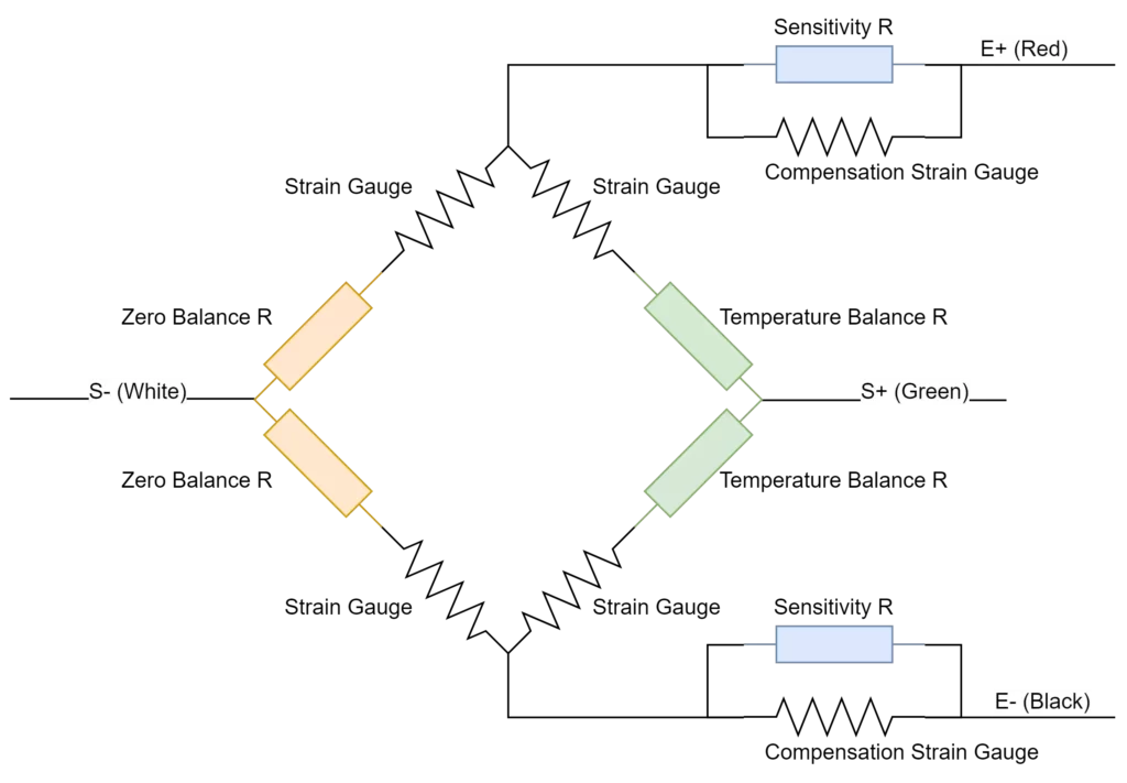
The wires extending from the load cell are typically color-coded as follows:
- Red: VCC (E+)
- Black: GND (E-)
- White: Output – (A-)
- Green: Output + (A+)
Applications
Strain gauge load cells find diverse applications, including:
- Monitoring changes in an object’s weight over time
- Measuring the weight of objects
- Detecting the presence of objects
- Estimating liquid levels within containers
- And more
Due to the subtle nature of strain changes during weight measurement, an amplifier becomes indispensable. The load cell arduino we are utilizing is often sold together with an arduino HX711 amplifier. Hence, we will utilize the HX711 amplifier to enhance and amplify the measurements.
HX711 Amplifier
The HX711 amplifier is a breakout board designed to simplify the process of reading load cells for weight measurement. One side of the board is dedicated to connecting the load cell wires, while the other side connects to the microcontroller. Communication between the HX711 and the microcontroller is established through a two-wire interface involving Clock and Data signals.
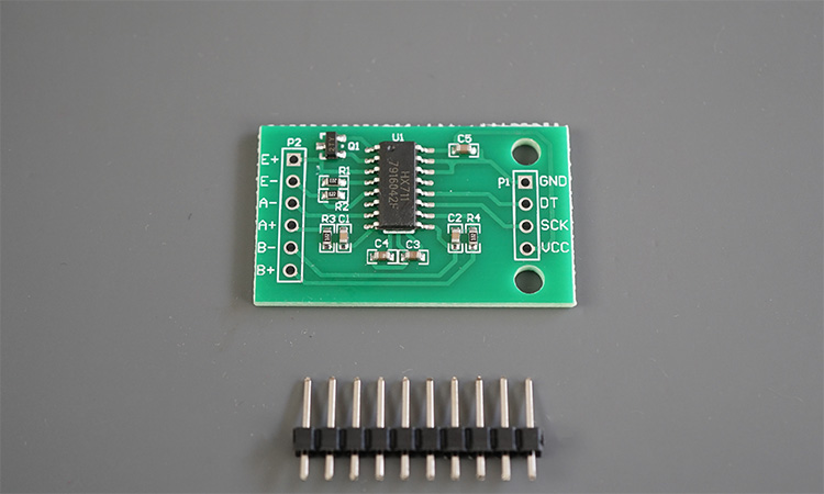
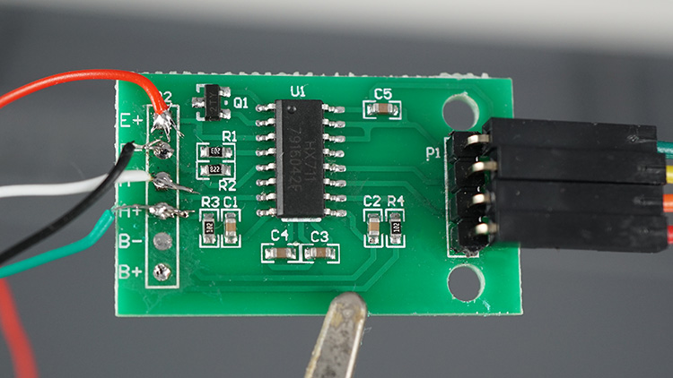
To establish a connection with the ESP8266, it’s necessary to solder header pins onto the GND, DT, SCK, and VCC pins. As for the hx711 load cell wires, I directly soldered them onto the E+, E-, A-, and A+ pins. It’s crucial to exercise caution during soldering to avoid damaging the delicate and thin load cell wires.
For more comprehensive details about the HX711 amplifier, you can refer to the HX711 datasheet.
Load Cell Setup
In our load cell kit, we received two acrylic plates along with screws to assemble the load cell into a functional scale. Alternatively, you can opt for wooden plates or create your own plates using 3D printing.
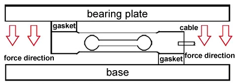
The essential objective is to affix the plates to the load cell in a manner that induces strain across the metal bar’s opposing ends. The lower plate serves as the foundation for the load cell arduino, while the upper plate functions as the platform for placing objects.
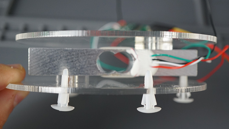
The illustration below provides a visual representation of how my hx711 load cell appears with the acrylic plates attached.
Where to Purchase Load Cells with HX711?
For the load cell paired with the arduino HX711, you can explore options on Maker Advisor to locate the most suitable price, whether it includes acrylic plates or not. These load cells come with various measurement ranges, typically featuring maximum weights such as 1kg, 5kg, 10kg, and 20kg.
Establishing Connection between Load Cell and HX711 Amplifier with ESP8266
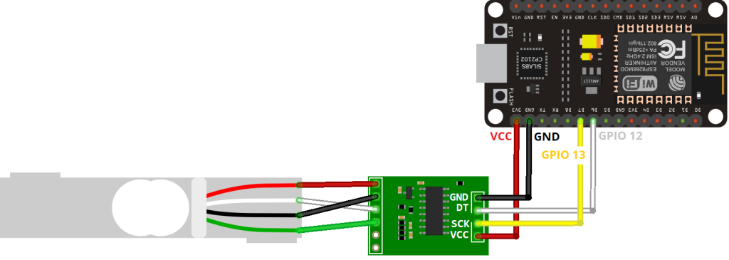
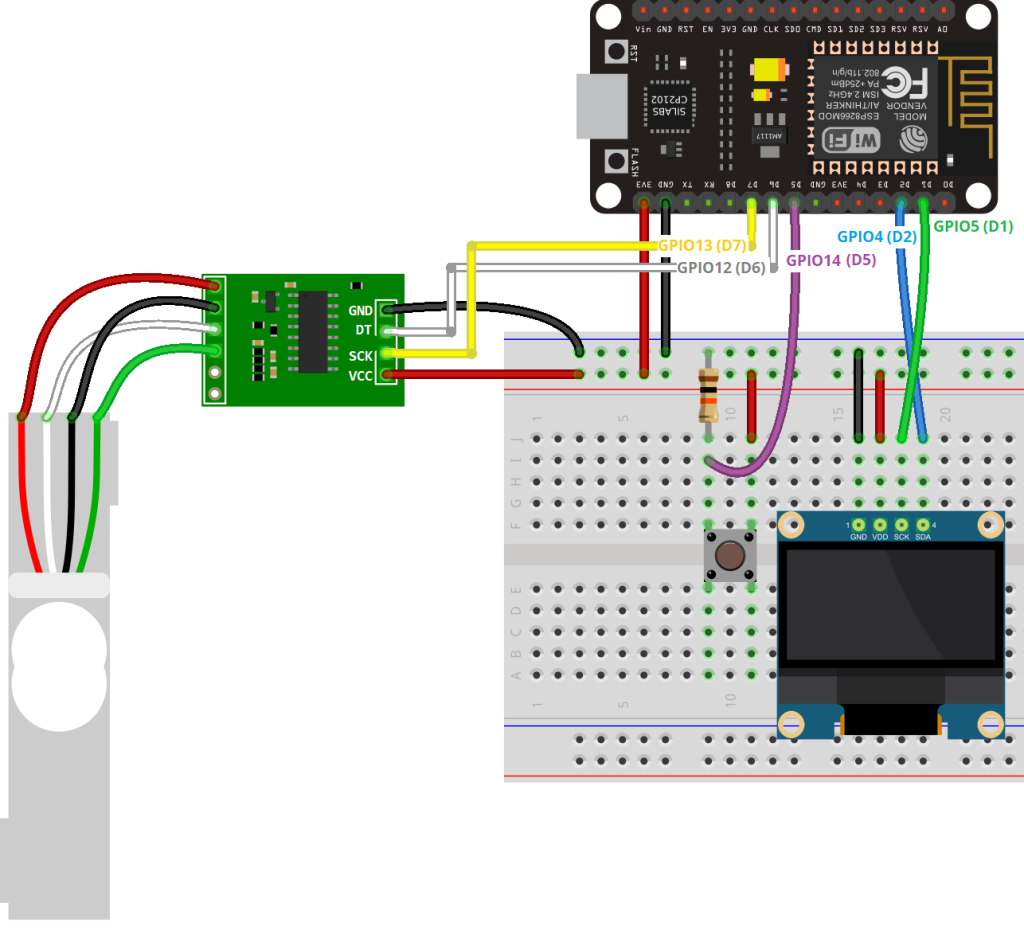
The HX711 amplifier employs a two-wire interface for communication, offering the flexibility to connect it to any available GPIOs on your selected microcontroller. In our setup, we’ve opted to link the data pin (DT) to GPIO 12 (D6) and the clock pin (CLK) to GPIO 13 (D7). Nonetheless, you can also make use of other suitable pins in accordance with the ESP8266 pinout guide.
For precise guidelines on creating the connections, kindly refer to the provided table or schematic diagram below. This resource will assist you in establishing the proper linkage between the load cell arduino and the ESP8266 board.
| Load Cell | HX711 | HX711 | ESP8266 |
| Red (E+) | E+ | GND | GND |
| Black (E-) | E- | DT | GPIO 12 (D6) |
| White (A-) | A- | SCK | GPIO 13 (D7) |
| Green (A+) | A+ | VCC | 3.3V |
Parts Required
| Component Name | Buy Now |
| ESP8266 NodeMCU CP2102 | Amazon |
| Load Cell Weight Sensor + HX711 ADC Module | Amazon |
| 0.96 Inch OLED I2C IIC Display Module | Amazon |
| Breadboard | Amazon |
| BOJACK 1000 Pcs 25 Values Resistor Kit 1 Ohm-1M Ohm with 5% 1/4W | Amazon |
Installing the HX711 Library
When it comes to acquiring load cell measurements through the HX711 amplifier, there exists a variety of libraries at your disposal. For our purpose, we will employ the “HX711” library developed by bodge. This particular library seamlessly functions with the Arduino, ESP8266, and ESP32 platforms.
Arduino IDE
For those employing the Arduino IDE, adhere to the subsequent instructions:
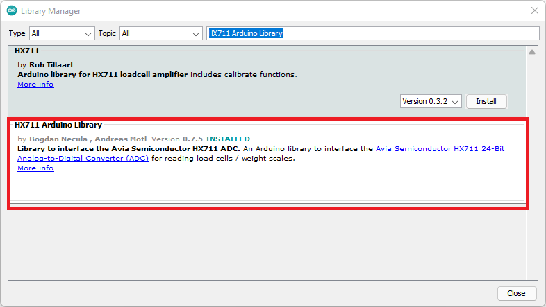
- Launch the Arduino IDE and navigate to “Sketch” > “Include Library” > “Manage Libraries.”
- Search for “HX711 Arduino Library” and proceed to install the library authored by Bogdan Necula.
VS Code with PlatformIO
Should you be utilizing VS Code alongside the PlatformIO extension for board programming, the following steps are imperative:
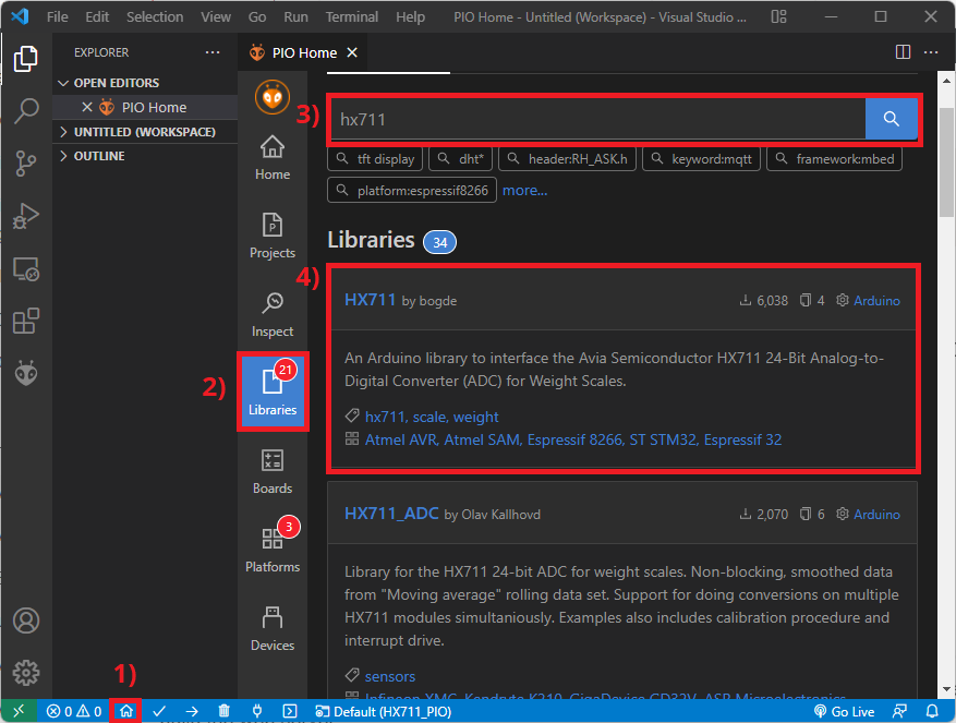
- Upon crafting a fresh project for your board within PlatformIO, access the PIO Home (located at the bottom bar, represented by a house icon). Subsequently, click on “Libraries.”
- Seek out “HX711” and opt for the library authored by bodge.
- Select “Add to Project” and choose the active project for integration.
Subsequent to these actions, traverse to your project directory and unveil the “platformio.ini” file. Within this file, you should encounter a line integrating the library in the ensuing format:
lib_deps = bogde/HX711@^0.7.5
Furthermore, insert the subsequent line to alter the Serial Monitor speed to 115200:
monitor_speed = 115200
Calibrating the Scale (ESP8266 with Load Cell)
Assuming you’ve successfully established the wiring connections between the load cell, the arduino HX711 amplifier, and the ESP8266, and you have your scale configured with two plates on opposing ends of the load cell, along with the HX711 library installed, you’re now ready to embark on the calibration process.
Before you proceed to obtain weight measurements from various objects, it is crucial to calibrate your load cell in order to determine the calibration factor. Since this factor is specific to your setup, skipping this section is strongly discouraged.
Here’s a step-by-step guide to calibrating your load cell:
- Begin by procuring an object with a known weight. For instance, a glass of water weighing 300g can be used for this purpose.
- Proceed to upload the provided code to your ESP8266. This code has been meticulously designed in accordance with the load cell arduino calibration instructions offered by the library documentation.
// Calibrating the load cell
#include <Arduino.h>
#include "HX711.h"

// HX711 circuit wiring
const int LOADCELL_DOUT_PIN = 12;
const int LOADCELL_SCK_PIN = 13;

HX711 scale;

void setup() {
  Serial.begin(115200);
  scale.begin(LOADCELL_DOUT_PIN, LOADCELL_SCK_PIN);
}

void loop() {

  if (scale.is_ready()) {
    scale.set_scale();
    Serial.println("Tare... remove any weights from the scale.");
    delay(5000);
    scale.tare();
    Serial.println("Tare done...");
    Serial.print("Place a known weight on the scale...");
    delay(5000);
    long reading = scale.get_units(10);
    Serial.print("Result: ");
    Serial.println(reading);
  }
  else {
    Serial.println("HX711 not found.");
  }
  delay(1000);
}

// calibration factor will be the (reading)/(known weight)
- Once you’ve successfully uploaded the code, launch the Serial Monitor at a baud rate of 115200 and reset the ESP8266 board.
- Carefully follow the instructions that appear on the Serial Monitor: Initiate the process by ensuring there are no weights on the scale (it will automatically tare itself). Subsequently, position an object with a known weight onto the scale and await the displayed value.
- Proceed to compute your calibration factor using the formula:
calibration factor = (reading)/(known weight)
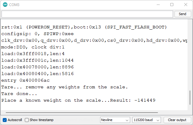
In our specific instance, the recorded reading is -141449 and the known weight is 300g. Hence, our calibration factor calculates to:
calibration factor = -141449/300 = -471.497
It’s essential to make a note of your obtained calibration factor, as you will require this information later. Please keep in mind that your calibration factor will differ from ours.
Given that the sensor’s output corresponds to the force exerted on the hx711 load cell, you possess the flexibility to calibrate your scale using your preferred unit of measurement. While I employed grams, you can opt for pounds, kilograms, or even unconventional units such as pieces of cat food (as demonstrated in a video by Andreas Spiess).
Weighting Objects (ESP8266 with Load Cell)
Now that you possess your calibration factor, you’re equipped to use the load cell arduino for weighing objects. Begin by measuring objects with known weights, and if the values aren’t accurate, you can repeat the calibration procedure.
Copy the provided code to your Arduino IDE. Prior to uploading it to your board, ensure to insert your calibration factor on line 43/44 of the code. The code below is a demonstration of the functions offered by the library and is provided as an example.
#include <Arduino.h>
#include "HX711.h"

// HX711 circuit wiring
const int LOADCELL_DOUT_PIN = 12;
const int LOADCELL_SCK_PIN = 13;

HX711 scale;

void setup() {
  Serial.begin(115200);
  Serial.println("HX711 Demo");
  Serial.println("Initializing the scale");

  scale.begin(LOADCELL_DOUT_PIN, LOADCELL_SCK_PIN);

  Serial.println("Before setting up the scale:");
  Serial.print("read: \t\t");
  Serial.println(scale.read());      // print a raw reading from the ADC

  Serial.print("read average: \t\t");
  Serial.println(scale.read_average(20));   // print the average of 20 readings from the ADC

  Serial.print("get value: \t\t");
  Serial.println(scale.get_value(5));   // print the average of 5 readings from the ADC minus the tare weight (not set yet)

  Serial.print("get units: \t\t");
  Serial.println(scale.get_units(5), 1);  // print the average of 5 readings from the ADC minus tare weight (not set) divided
            // by the SCALE parameter (not set yet)

  scale.set_scale(-478.507);
  //scale.set_scale(-471.497);                      // this value is obtained by calibrating the scale with known weights; see the README for details
  scale.tare();               // reset the scale to 0

  Serial.println("After setting up the scale:");

  Serial.print("read: \t\t");
  Serial.println(scale.read());                 // print a raw reading from the ADC

  Serial.print("read average: \t\t");
  Serial.println(scale.read_average(20));       // print the average of 20 readings from the ADC

  Serial.print("get value: \t\t");
  Serial.println(scale.get_value(5));   // print the average of 5 readings from the ADC minus the tare weight, set with tare()

  Serial.print("get units: \t\t");
  Serial.println(scale.get_units(5), 1);        // print the average of 5 readings from the ADC minus tare weight, divided
            // by the SCALE parameter set with set_scale

  Serial.println("Readings:");
}

void loop() {
  Serial.print("one reading:\t");
  Serial.print(scale.get_units(), 1);
  Serial.print("\t| average:\t");
  Serial.println(scale.get_units(10), 5);

  scale.power_down();             // put the ADC in sleep mode
  delay(5000);
  scale.power_up();
}
This code is intended to exhibit various functions of the library. It allows you to understand how to use most of the functions effectively. By following this example, you can optimize the use of your load cell for weighing purposes.
How the Code Operates
To comprehend the functionality of the code, initiate by importing the necessary libraries. We’ve included the header file Arduino.h in case you’re using PlatformIO rather than the Arduino IDE.
#include <Arduino.h>
#include "HX711.h"
The subsequent lines establish the GPIO pins that will be employed for connecting to the arduino HX711 amplifier. We have designated GPIO pins 12 and 13, although you can utilize other suitable GPIO pins as needed.
const int LOADCELL_DOUT_PIN = 12;
const int LOADCELL_SCK_PIN = 13;
Create an instance of the HX711 library named “scale,” which will be utilized to retrieve measurements later in the code.
HX711 scale;
setup() Function
Inside the setup() function, initialize the Serial monitor for communication.
Serial.begin(115200);
Initiate the load cell by invoking the begin() method on the scale object and providing the relevant GPIO pins as arguments.
scale.begin(LOADCELL_DOUT_PIN, LOADCELL_SCK_PIN);
Subsequently, various methods are invoked for obtaining readings using the library:
read(): Retrieves a raw reading from the sensor.read_average(number of readings): Obtains the average of the latest specified number of readings.get_value(number of readings): Acquires the average of the last specified number of readings, excluding the tare weight.get_units(number of readings): Fetches the average of the last specified number of readings, excluding the tare weight, divided by the calibration factor. This provides a reading in the desired units.
Serial.println("Before setting up the scale:");
Serial.print("read: \t\t");
Serial.println(scale.read());      // print a raw reading from the ADC

Serial.print("read average: \t\t");
Serial.println(scale.read_average(20));   // print the average of 20 readings from the ADC

Serial.print("get value: \t\t");
Serial.println(scale.get_value(5));   // print the average of 5 readings from the ADC minus the tare weight (not set yet)

Serial.print("get units: \t\t");
Serial.println(scale.get_units(5), 1);  // print the average of 5 readings from the ADC minus tare weight (not set) divided
// by the SCALE parameter (not set yet)
In the subsequent line, remember to insert your calibration factor. The set_scale() method is utilized for this purpose.
scale.set_scale(INSERT YOUR CALIBRATION FACTOR)
Invoke the tare() method to reset the scale to zero.
scale.tare(); // reset the scale to 0
After completing this setup, the scale should be primed to deliver precise readings in your chosen unit. The example then invokes the same aforementioned methods for comparative purposes before and after configuring the scale.
Serial.print("read: \t\t");
Serial.println(scale.read());                 // print a raw reading from the ADC

Serial.print("read average: \t\t");
Serial.println(scale.read_average(20));       // print the average of 20 readings from the ADC

Serial.print("get value: \t\t");
Serial.println(scale.get_value(5));   // print the average of 5 readings from the ADC minus the tare weight, set with tare()

Serial.print("get units: \t\t");
Serial.println(scale.get_units(5), 1);        // print the average of 5 readings from the ADC minus tare weight, divided
// by the SCALE parameter set with set_scale
loop() Function
In the loop() function, the example utilizes the get_units() method in two ways: to retrieve a single reading (without parameters) and to obtain the average of the last 10 readings.
Serial.print("one reading:\t");
Serial.print(scale.get_units(), 1);
Serial.print("\t| average:\t");
Serial.println(scale.get_units(10), 5);
The code employs the power_down() method to deactivate the ADC responsible for reading the sensor. It then introduces a delay of 5 seconds before activating the ADC again using the power_up() method. The loop() continues, ensuring that new readings are displayed on the Serial Monitor every 5 seconds.
scale.power_down();             // put the ADC in sleep mode
delay(5000);
scale.power_up();
Demonstration
Proceed by uploading the code to your ESP8266 board. Upon successful upload, launch the Serial Monitor with a baud rate set to 115200.
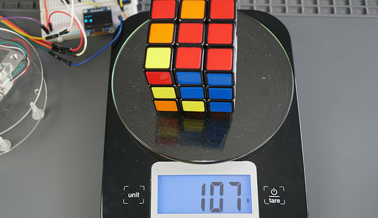
Allow the code to execute for a few seconds, granting it the time needed to configure the scale (you’ll observe a corresponding message on the Serial Monitor). Subsequently, position an object of your choice on the scale for measurement, and the results will be presented on the Serial Monitor.
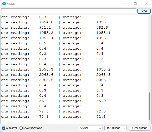
In my experimentation, I assessed various objects and cross-referenced the obtained values with those from my kitchen scale. Remarkably, the outcomes aligned perfectly. This indicates that my ESP8266-powered scale exhibits accuracy at least equivalent to that of my kitchen scale.
Digital Scale with ESP8266
In this section, we’ll create a simple digital scale with the ESP8266. We’ll add an OLED display to show the results and a pushbutton to tare the scale.
Parts Required
Here’s a list of the parts required for this project:
- ESP8266
- Load Cell with HX711 Amplifier
- I2C SSD1306 OLED Display
- Pushbutton
- 10K Ohm Resistor
- Breadboard
- Jumper Wires
Schematic Diagram
Add an OLED display and a pushbutton to your previous circuit on the following pins:
| OLED Display | ESP8266 |
| VCC | 3.3V or 5V* |
| GND | GND |
| SDA | GPIO 4 (D2) |
| SCL | GPIO 5 (D1) |
*connect to 3.3V or 5V depending on the model.
Wire the pushbutton via a 10kOhm pull-down resistor to GPIO 14 (D5). The other lead of the pushbutton should be connected to 3.3V. You can use any other suitable GPIO.
You can follow the next schematic diagram to wire your parts.
ESP8266 Digital Scale – Code
To ensure simplicity, we will handle the pushbutton functionality using a straightforward library designed to detect button presses while accounting for debouncing. This approach eliminates the need for complex coding to manage this aspect. For communication with the OLED display, we will utilize the Adafruit SSD1306 and Adafruit GFX libraries.
Pushbutton Library
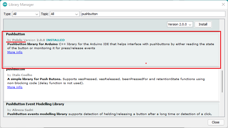
Several libraries are available to handle various button-related functionalities. For this project, we will adopt the “pushbutton” library by Pololu due to its suitability for our requirements. To integrate this library into your Arduino IDE, follow these steps:
- Open the Arduino IDE and navigate to “Sketch” > “Include Library” > “Manage Libraries.”
- Search for “pushbutton” and proceed to install the “Pushbutton” library by Pololu.
Alternatively, if you choose not to use this library, you can manually implement the debounce code (which is not overly complex). For an example of debounce code, within the Arduino IDE, navigate to File > Examples > Digital > Debounce.
OLED Libraries
We will make use of the following libraries to control the OLED display. Ensure that you have these libraries installed:
To install these libraries, use the Arduino Library Manager. Access “Sketch” > “Include Library” > “Manage Libraries,” and search for the respective library names.
Installing Libraries – PlatformIO
If you are using Visual Studio Code with the PlatformIO extension, follow these steps to install the libraries:
- After creating a new project for your board in PlatformIO, go to the PIO Home (click on the house icon on the bottom bar). Then, click on “Libraries.” Search for “pushbutton” and select the “Pushbutton” library by Pololu.
- Click on “Add to Project” and select the project you are currently working on.
- Repeat the above process for the “Adafruit SSD1306” and “Adafruit GFX” libraries. Additionally, ensure that you also add the “HX711” library.
In your “platformio.ini” file, include the following lines that list all the required libraries (also update the Serial Monitor speed to 115200):
monitor_speed = 115200
lib_deps =
	bogde/HX711@^0.7.5
	pololu/Pushbutton@^2.0.0
        adafruit/Adafruit SSD1306@^2.4.6
	adafruit/Adafruit GFX Library@^1.10.10
Code
Copy the provided code to your Arduino IDE. Before uploading it to the ESP8266, make sure you insert your calibration factor that you obtained previously.
// Complete project details at https://RandomNerdTutorials.com/esp8266-load-cell-hx711/
// Library HX711 by Bogdan Necula: https://github.com/bogde/HX711
// Library: pushbutton by polulu: https://github.com/pololu/pushbutton-arduino

#include <Arduino.h>
#include "HX711.h"
#include <Wire.h>
#include <Adafruit_GFX.h>
#include <Adafruit_SSD1306.h>
#include <Pushbutton.h>

// HX711 circuit wiring
const int LOADCELL_DOUT_PIN = 12;
const int LOADCELL_SCK_PIN = 13;

HX711 scale;
int reading;
int lastReading;
//REPLACE WITH YOUR CALIBRATION FACTOR
#define CALIBRATION_FACTOR -478.507

//OLED Display
#define SCREEN_WIDTH 128 // OLED display width, in pixels
#define SCREEN_HEIGHT 64 // OLED display height, in pixels

// Declaration for an SSD1306 display connected to I2C (SDA, SCL pins)
#define OLED_RESET     -1 // Reset pin # (or -1 if sharing Arduino reset pin)
Adafruit_SSD1306 display(SCREEN_WIDTH, SCREEN_HEIGHT, &Wire, OLED_RESET);

//Button
#define BUTTON_PIN 14
Pushbutton button(BUTTON_PIN);

void displayWeight(int weight){
  display.clearDisplay();
  display.setTextSize(1);
  display.setTextColor(WHITE);
  display.setCursor(0, 10);
  // Display static text
  display.println("Weight:");
  display.display();
  display.setCursor(0, 30);
  display.setTextSize(2);
  display.print(weight);
  display.print(" ");
  display.print("g");
  display.display();
}

void setup() {
  Serial.begin(115200);

  if(!display.begin(SSD1306_SWITCHCAPVCC, 0x3C)) {
    Serial.println(F("SSD1306 allocation failed"));
    for(;;);
  }
  delay(2000);
  display.clearDisplay();
  display.setTextColor(WHITE);

  Serial.println("Initializing the scale");
  scale.begin(LOADCELL_DOUT_PIN, LOADCELL_SCK_PIN);

  scale.set_scale(CALIBRATION_FACTOR);   // this value is obtained by calibrating the scale with known weights
  scale.tare();               // reset the scale to 0
}

void loop() {

  if (button.getSingleDebouncedPress()){
    Serial.print("tare...");
    scale.tare();
  }

  if (scale.wait_ready_timeout(200)) {
    reading = round(scale.get_units());
    Serial.print("Weight: ");
    Serial.println(reading);
    if (reading != lastReading){
      displayWeight(reading);
    }
    lastReading = reading;
  }
  else {
    Serial.println("HX711 not found.");
  }
}
Remember to upload the code to your ESP8266 board and follow the subsequent steps mentioned in the original instructions for full functionality.
How the Code Functions
Commence by incorporating the necessary libraries:
#include <Arduino.h>
#include "HX711.h"
#include <Wire.h>
#include <Adafruit_GFX.h>
#include <Adafruit_SSD1306.h>
#include <Pushbutton.h>
Define the pins for the arduino HX711 (load cell) — maintaining consistency with previous examples:
// HX711 circuit wiring
const int LOADCELL_DOUT_PIN = 12;
const int LOADCELL_SCK_PIN = 13;
Instantiate an HX711 instance named “scale”:
HX711 scale;
The ensuing variables will retain the present weight reading and the preceding weight reading. The intention is to update the OLED display only if there’s a new reading. Hence, these two variables are utilized. Also, to prevent excessive sensitivity, we’re utilizing integers instead of decimals for gram measurements. If decimal precision is needed, float variables can be employed:
int reading;
int lastReading;
Ensure to substitute the subsequent value with your calibration factor. For example, if your value is negative:
#define CALIBRATION_FACTOR -471.497
Next, outline the OLED width and height:
#define SCREEN_WIDTH 128 // OLED display width, in pixels
#define SCREEN_HEIGHT 64 // OLED display height, in pixels
Generate an instance of the Adafruit_SSD1306 library named “display”:
Adafruit_SSD1306 display(SCREEN_WIDTH, SCREEN_HEIGHT, &Wire, OLED_RESET);
Define the GPIO for button reading and establish a Pushbutton object named “button” associated with that pin:
#define BUTTON_PIN 14
Pushbutton button(BUTTON_PIN);
displayWeight() function
A function labeled “displayWeight()” is established, designed to display the specified weight on the OLED:
void displayWeight(int weight){
  display.clearDisplay();
  display.setTextSize(1);
  display.setTextColor(WHITE);
  display.setCursor(0, 10);
  // Display static text
  display.println("Weight:");
  display.display();
  display.setCursor(0, 30);
  display.setTextSize(2);
  display.print(weight);
  display.print(" ");
  display.print("g");
  display.display();
}
Unfamiliar with the OLED display? Refer to: ESP8266 OLED Display with Arduino IDE.
setup()
Within the “setup()” function, initialize the Serial Monitor:
Serial.begin(115200);
Initiate the OLED display:
if(!display.begin(SSD1306_SWITCHCAPVCC, 0x3C)) {
  Serial.println(F("SSD1306 allocation failed"));
  for(;;);
}
delay(2000);
display.clearDisplay();
display.setTextColor(WHITE);
And finally, initialize the load cell arduino:
Serial.println("Initializing the scale");
scale.begin(LOADCELL_DOUT_PIN, LOADCELL_SCK_PIN);

scale.set_scale(CALIBRATION_FACTOR);   // this value is obtained by calibrating the scale with known weights
scale.tare();               // reset the scale to 0
loop()
The pushbutton library facilitates waiting for events upon pushbutton presses or releases. In this scenario, we examine whether the pushbutton was pressed using the “getSingleDebouncePress()” method, and invoke the “tare()” function if the button was indeed pressed:
if (button.getSingleDebouncedPress()){
  Serial.print("tare...");
  scale.tare();
}
The HX711 introduces a non-blocking technique for obtaining readings. It sets a maximum timeout to await hardware initialization and prevents blocking of your code due to scale disconnection or hardware failures:
if (scale.wait_ready_timeout(200)) {
  reading = round(scale.get_units());
  Serial.print("Weight: ");
  Serial.println(reading);
Inside the “loop()”, fresh readings are perpetually acquired and compared to the most recent reading. When a novel measurement is taken, the “displayWeight()” function is invoked to update the OLED display:
if (reading != lastReading){
  displayWeight(reading);
}
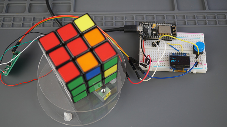
Demonstration
Upon uploading the code to your board, you’re prepared to weigh objects using the hx711 load cell. The OLED display will showcase the readings. The scale can be zeroed using the pushbutton.
Concluding Remarks
Throughout this tutorial, you’ve gained valuable insights into connecting a strain gauge load cell to the ESP8266 using the arduino HX711 amplifier. The load cell’s output correlates with the applied force, allowing you to calibrate it for various units such as grams, kilograms, pounds, or any other unit relevant to your project.
In summary, you’ve grasped the process of calibrating the scale and obtaining object weights. Moreover, you’ve learned how to construct a straightforward digital scale utilizing the ESP8266, featuring an OLED display for showcasing measurements and a pushbutton for zeroing the scale.
We trust that this tutorial has served as a helpful introduction to working with load cells. Beyond their weight-measuring capacity, these load cells hold potential for a multitude of applications. These span from object detection and liquid level estimation in tanks to calculating water evaporation rates and monitoring your pet’s food bowl contents.
Given the ESP8266’s Wi-Fi capabilities, consider venturing into the realm of IoT scales. Imagine building a web server to display readings on your smartphone’s browser, recording measurements in a Firebase database accessible from anywhere, or receiving notifications when weights fall below specified thresholds through email or platforms like Telegram. Feel free to share your ideas for IoT tutorials incorporating load cells in the comments section below. Your input is valuable in shaping future content.
Related article
- Ultimate Guide: Crafting an ESP8266 Weather Station Using BME280
- Mastering Interrupts and Timers: ESP8266 Development Guide
- BMP388 Barometric Sensor Setup for ESP8266 NodeMCU (Arduino IDE)
- Enhanced Monitoring: Multiple DS18B20s on ESP8266 Web Server
- ESP8266 NodeMCU and BME680 Sensor Tutorial: Read Gas, Pressure, Humidity, Temp


