

If you’ve ever tried linking an LCD display to an Arduino, you likely observed that it consumes a substantial number of Arduino pins. Even in 4-bit mode, it demands seven connections, which is half of the available digital I/O pins on the Arduino.
The remedy is to opt for an I2C LCD display. This type of display only necessitates two I/O pins, which are distinct from the standard digital I/O pin set and can be utilized concurrently with other I2C devices.
Hardware Overview
An average I2C LCD display comprises a character LCD display based on HD44780 and an I2C LCD adapter. Let’s delve into their details.
Character LCD Display
True to its name, these LCDs excel in presenting characters. For instance, a 16×2 character LCD can exhibit 32 ASCII characters spread across two rows.
On close inspection, you’ll notice small rectangles for each character on the screen, along with the pixels forming a character. Each of these rectangles forms a grid of 5×8 pixels.
For more details about character LCD displays, please consult our comprehensive guide.
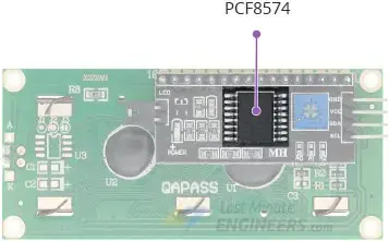
I2C LCD Adapter
The core of the adapter features an 8-bit I/O expander chip – PCF8574. This chip transforms the I2C data from an Arduino into the parallel data necessary for an LCD display.
The board is equipped with a small trimpot for precise adjustments to the display’s contrast.
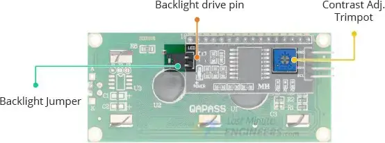
A jumper on the board supplies power to the backlight. To regulate the backlight’s intensity, you can remove the jumper and apply external voltage to the header pin labeled ‘LED.’
LCD I2C Address Configuration
If you have multiple devices connected to the same I2C bus, it may be necessary to assign a unique I2C address to the LCD adapter to prevent conflicts with other I2C devices.
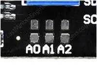
To achieve this, the adapter is equipped with three solder jumpers/pads labeled A0, A1, and A2. The I2C address is determined by shorting a jumper with a solder blob.
It’s important to note that various companies, such as Texas Instruments and NXP Semiconductors, produce the same PCF8574 chip, and the I2C address of your LCD is contingent on the chip manufacturer.
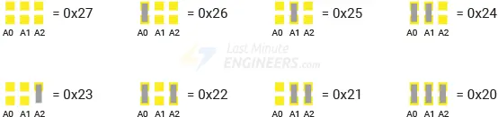
If your LCD utilizes Texas Instruments’ PCF8574 chip:
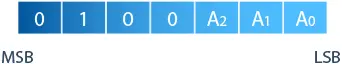
Referencing Texas Instruments’ datasheet, the three address selection bits (A0, A1, and A2) are positioned at the end of the 7-bit I2C address register.
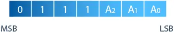
Since there are three address inputs with two possible states, HIGH or LOW, eight (2^3) unique combinations (addresses) are feasible.
All three address inputs default to HIGH due to onboard pullups, resulting in the PCF8574 having a default I2C address of 0x27.
Shorting a solder jumper pulls the respective address input LOW. If all three jumpers are shorted, the address becomes 0x20. Consequently, the address range spans from 0x20 to 0x27.
You can configure a different I2C address as outlined in the provided table.
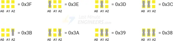
If your LCD features NXP’s PCF8574 chip:
According to NXP Semiconductors’ datasheet, the three address selection bits (A0, A1, and A2) are also found at the end of the 7-bit I2C address register, but the remaining bits in the address register differ.
With three address inputs capable of being either HIGH or LOW, eight (2^3) distinct combinations (addresses) are possible.
Similar to Texas Instruments, all three address inputs are pulled HIGH by onboard pullups, resulting in the PCF8574 having a default I2C address of 0x3F.
Shorting a solder jumper pulls the respective address input LOW. If all three jumpers are shorted, the address becomes 0x38. Consequently, the address range spans from 0x38 to 0x3F.
You can configure a different I2C address using the provided table.
I2C LCD Display Pinout
The I2C LCD Display has only four pins. The following is the pinout:
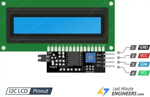
- GND is a ground pin.
- VCC is the power supply pin. Connect it to the 5V output of the Arduino or an external 5V power supply.
- SDA is the I2C data pin.
- SCL is the I2C clock pin.
Connecting an I2C LCD Display to an Arduino
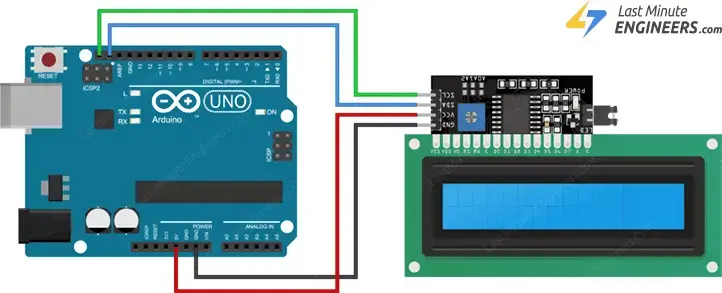
The process of wiring an I2C LCD to an Arduino is considerably simpler compared to connecting a standard LCD, requiring only four pins.
To initiate the connection, link the VCC pin to the 5V output of the Arduino and the GND pin to the ground.
Next, focus on the pins dedicated to I2C communication. It’s crucial to recognize that each Arduino board features distinct I2C pins, and proper connection is essential. For Arduino boards utilizing the R3 layout, the SDA (data line) and SCL (clock line) are located on the pin headers near the AREF pin, often labeled as A5 (SCL) and A4 (SDA).
The ensuing table provides a reference for the pin connections:
| I2C LCD | Arduino |
| VCC | 5V |
| GND | GND |
| SCL | SCL or A5 |
| SDA | SDA or A4 |
The diagram below shows how to connect everything.
Parts Required
| Component Name | Buy Now |
| Arduino Uno REV3 | Amazon |
| I2C 1602 LCD Display Module | Amazon |
| Breadboard | Amazon |
| BOJACK 1000 Pcs 25 Values Resistor Kit 1 Ohm-1M Ohm with 5% 1/4W | Amazon |
Calibrating LCD Contrast
Following the completion of the LCD wiring, it becomes necessary to fine-tune the contrast settings. The I2C module features a potentiometer, adjustable with a small screwdriver.
Activate the Arduino, and the backlight will illuminate. Rotating the potentiometer knob will result in the appearance of the first row of rectangles. Congratulations on reaching this stage! Your LCD is now operating correctly.
Installing the Library
Before advancing, it’s essential to install the LiquidCrystal_I2C library. This library facilitates the management of I2C displays with functions closely resembling those of the LiquidCrystal library.
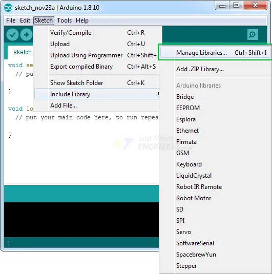
To install the library, go to Sketch > Include Library > Manage Libraries… Wait for the Library Manager to download the library index and update the list of installed libraries.
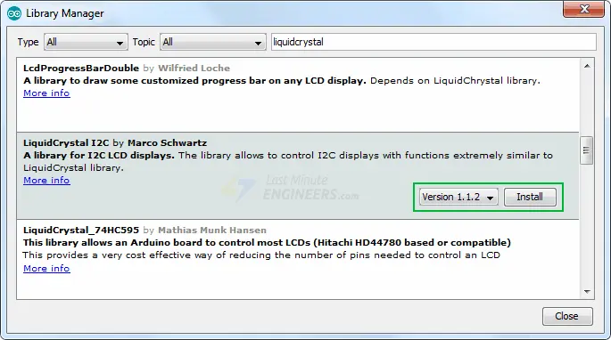
Refine your search by entering ‘liquidcrystal.’ Locate the LiquidCrystal I2C library by Marco Schwartz. Click on that entry and proceed to install it.
Identifying the I2C Address
As mentioned earlier, the I2C address of your LCD is contingent upon the manufacturer. If your LCD incorporates a PCF8574 chip from Texas Instruments, its I2C address is 0x27; whereas, with a PCF8574 chip from NXP Semiconductors, the I2C address becomes 0x3F.
In case you’re uncertain about your LCD’s I2C address, you can execute a straightforward I2C scanner sketch. This sketch scans the I2C bus, revealing the address of each detected I2C device.
Locate this scanner sketch under File > Examples > Wire > i2c_scanner.
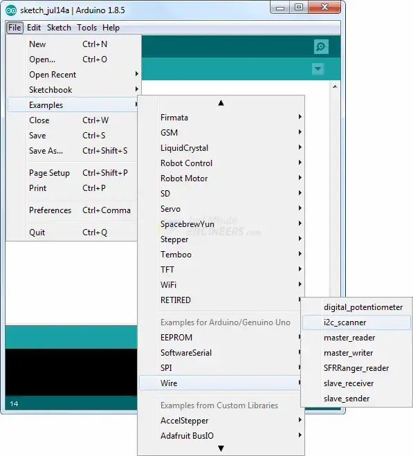
Load the i2c_scanner sketch into your Arduino IDE for implementation.
#include <Wire.h>

void setup() {
  Wire.begin();

  Serial.begin(9600);
  while (!Serial); // Leonardo: wait for serial monitor
  Serial.println("\nI2C Scanner");
}

void loop() {
  int nDevices = 0;

  Serial.println("Scanning...");

  for (byte address = 1; address < 127; ++address) {
    // The i2c_scanner uses the return value of
    // the Write.endTransmisstion to see if
    // a device did acknowledge to the address.
    Wire.beginTransmission(address);
    byte error = Wire.endTransmission();

    if (error == 0) {
      Serial.print("I2C device found at address 0x");
      if (address < 16) {
        Serial.print("0");
      }
      Serial.print(address, HEX);
      Serial.println("  !");

      ++nDevices;
    } else if (error == 4) {
      Serial.print("Unknown error at address 0x");
      if (address < 16) {
        Serial.print("0");
      }
      Serial.println(address, HEX);
    }
  }
  if (nDevices == 0) {
    Serial.println("No I2C devices found\n");
  } else {
    Serial.println("done\n");
  }
  delay(5000); // Wait 5 seconds for next scan
}
After you’ve uploaded the sketch, launch the serial monitor at 9600 baud. You should see the I2C address of your I2C LCD display.
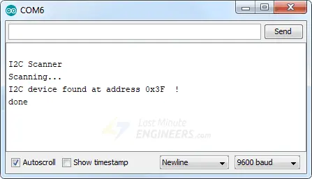
Please make a note of this address. You’ll need it in later examples.
Simple Arduino Sketch – Hello World
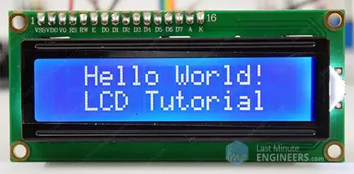
The provided test sketch will display ‘Hello World!’ on the first line of the LCD and ‘LCD Tutorial’ on the second line.
Prior to uploading the sketch, a minor modification is required to ensure its functionality for your setup. You need to specify the I2C address of your LCD, along with the display dimensions, in the LiquidCrystal_I2C constructor. If you’re utilizing a 16×2 character LCD, input 16 and 2; for a 20×4 character LCD, input 20 and 4.
// enter the I2C address and the dimensions of your LCD here
LiquidCrystal_I2C lcd(0x3F, 16, 2);
Once you are done, go ahead and try the sketch.
#include <LiquidCrystal_I2C.h>

LiquidCrystal_I2C lcd(0x3F,16,2);  // set the LCD address to 0x3F for a 16 chars and 2 line display

void setup() {
  lcd.init();
  lcd.clear();
  lcd.backlight();      // Make sure backlight is on

  // Print a message on both lines of the LCD.
  lcd.setCursor(2,0);   //Set cursor to character 2 on line 0
  lcd.print("Hello world!");

  lcd.setCursor(2,1);   //Move cursor to character 2 on line 1
  lcd.print("LCD Tutorial");
}

void loop() {
}
This is what you should see on the screen.
Code Explanation:
Commencing with the inclusion of the LiquidCrystal_I2C library:
#include <LiquidCrystal_I2C.h>
The subsequent step involves creating an object of the LiquidCrystal_I2C class. The constructor of LiquidCrystal_I2C takes three parameters: I2C address, the number of columns, and the number of rows of the display.
LiquidCrystal_I2C lcd(0x3F,16,2);
Within the setup section, three functions are invoked. The first function is init(), initializing the interface to the LCD. The second function, clear(), erases the LCD screen and positions the cursor in the upper-left corner. The third function, backlight(), activates the LCD backlight.
lcd.init();
lcd.clear();
lcd.backlight();
The setCursor(2, 0) function is then utilized to shift the cursor to the third column of the first row. This cursor position determines where the new text will appear on the LCD. The assumption is that the upper-left corner is represented by col=0 and row=0.
lcd.setCursor(2,0);
Subsequently, the print() function is employed to display “Hello world!” on the LCD.
lcd.print("Hello world!");
Similarly, the following two lines of code reposition the cursor to the third column of the second row and print ‘LCD Tutorial’ on the LCD.
lcd.setCursor(2,1);
lcd.print("LCD Tutorial");
Additional Functions of the LiquidCrystal_I2C Library
The LiquidCrystal_I2C object offers several valuable functions that can be effectively utilized. Here are some of them:
- The
lcd.home()function situates the cursor in the upper-left corner of the LCD without clearing the display.
- Utilizing the
lcd.blink()function displays a blinking block of 5×8 pixels at the position where the next character will be written.
- The
lcd.noBlink()function deactivates the blinking LCD cursor.
- With the
lcd.cursor()function, an underscore (line) is exhibited at the position where the next character will be written.
- The
lcd.noCursor()function conceals the LCD cursor.
- The
lcd.scrollDisplayRight()function scrolls the display content one space to the right. For continuous scrolling, it can be incorporated within aforloop.
- Similarly, the
lcd.scrollDisplayLeft()function scrolls the display content one space to the left. Employ this function inside aforloop for continuous scrolling.
- The
lcd.noDisplay()function deactivates the LCD display without erasing the currently shown text.
- By using the
lcd.display()function, the LCD display is reactivated after being turned off withnoDisplay(). This action restores the text (and cursor) previously visible on the display.
Creating and Displaying Custom Characters
If you find the default font unappealing, you have the option to craft your own custom characters (glyphs) and symbols. This becomes useful when you need to showcase a character that isn’t part of the standard ASCII character set.
As explained earlier in this tutorial, a character is composed of a 5×8 pixel matrix. Therefore, defining your custom character involves fitting it within this matrix, achievable through the use of the createChar() function.
To employ createChar(), you must initially construct an 8-byte array. Each byte in the array corresponds to a row in a 5×8 matrix. Within a byte, the binary digits 0 and 1 designate which pixels in a row should be turned OFF or ON.
All these user-defined characters find their storage space in the LCD’s CGRAM (Character Generator RAM).
CGROM is non-volatile memory retaining data even without power, storing the font displayed on a character LCD. For example, when you command a character LCD to show the letter ‘A,’ CGROM contains the data specifying which pixels to activate for the appearance of ‘A.’
CGRAM, on the other hand, is volatile memory that loses its data when the power is removed. It serves as additional memory for storing user-defined characters. The CGRAM’s capacity is limited to 64 bytes. Consequently, for a 5×8 pixel LCD, only 8 user-defined characters can be stored in CGRAM, and for a 5×10 pixel LCD, the limit is 4.
Custom Character Generator
Designing your own custom characters is now simpler than ever! Introducing our user-friendly tool, the Custom Character Generator. Notice the blue grid below? You can effortlessly click on any pixel to either set or clear it. As you click, the corresponding code for the character is dynamically generated next to the grid. This generated code can be directly integrated into your Arduino sketch.
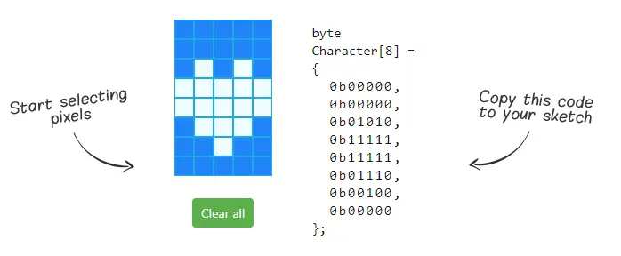
The creative possibilities are boundless. The only constraint lies in the fact that the LiquidCrystal_I2C library accommodates only eight custom characters. However, let’s not dwell on limitations; instead, focus on the positive side – having eight characters at our disposal is certainly something to appreciate.
Arduino Example Code
The sketch below demonstrates how to display custom characters on the LCD.
#include <LiquidCrystal_I2C.h>
LiquidCrystal_I2C lcd(0x3F, 16, 2); // set the LCD address to 0x3F for a 16 chars and 2 line display
// make some custom characters:
byte Heart[8] = {
0b00000,
0b01010,
0b11111,
0b11111,
0b01110,
0b00100,
0b00000,
0b00000
};
byte Bell[8] = {
0b00100,
0b01110,
0b01110,
0b01110,
0b11111,
0b00000,
0b00100,
0b00000
};
byte Alien[8] = {
0b11111,
0b10101,
0b11111,
0b11111,
0b01110,
0b01010,
0b11011,
0b00000
};
byte Check[8] = {
0b00000,
0b00001,
0b00011,
0b10110,
0b11100,
0b01000,
0b00000,
0b00000
};
byte Speaker[8] = {
0b00001,
0b00011,
0b01111,
0b01111,
0b01111,
0b00011,
0b00001,
0b00000
};
byte Sound[8] = {
0b00001,
0b00011,
0b00101,
0b01001,
0b01001,
0b01011,
0b11011,
0b11000
};
byte Skull[8] = {
0b00000,
0b01110,
0b10101,
0b11011,
0b01110,
0b01110,
0b00000,
0b00000
};
byte Lock[8] = {
0b01110,
0b10001,
0b10001,
0b11111,
0b11011,
0b11011,
0b11111,
0b00000
};
void setup()
{
lcd.init();
// Make sure backlight is on
lcd.backlight();
// create a new characters
lcd.createChar(0, Heart);
lcd.createChar(1, Bell);
lcd.createChar(2, Alien);
lcd.createChar(3, Check);
lcd.createChar(4, Speaker);
lcd.createChar(5, Sound);
lcd.createChar(6, Skull);
lcd.createChar(7, Lock);
// Clears the LCD screen
lcd.clear();
// Print a message to the lcd.
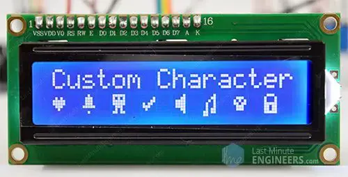
lcd.print("Custom Character");
}
// Print All the custom characters
void loop()
{
lcd.setCursor(0, 1);
lcd.write(0);
lcd.setCursor(2, 1);
lcd.write(1);
lcd.setCursor(4, 1);
lcd.write(2);
lcd.setCursor(6, 1);
lcd.write(3);
lcd.setCursor(8, 1);
lcd.write(4);
lcd.setCursor(10, 1);
lcd.write(5);
lcd.setCursor(12, 1);
lcd.write(6);
lcd.setCursor(14, 1);
lcd.write(7);
}
The output appears as shown.
Code Explanation:
Following the library inclusion and LCD object creation, custom character arrays are defined. Each array comprises 8 bytes, where each byte corresponds to a row within a 5×8 matrix.
This sketch incorporates eight custom characters, exemplified by the Heart[8] array. The binary digits (0s and 1s) are configured to form the shape of a heart. A 0 deactivates the pixel, while a 1 activates it.
byte Heart[8] = {
0b00000,
0b01010,
0b11111,
0b11111,
0b01110,
0b00100,
0b00000,
0b00000
};
Within the setup, the createChar() function is utilized to generate a custom character. This function requires two parameters: a number between 0 and 7 to reserve one of the eight supported custom characters, and the name of the array.
lcd.createChar(0, Heart);
In the loop, for displaying the custom character, the write() function is invoked, taking as an argument the number of the reserved character.
lcd.setCursor(0, 1);
lcd.write(0);
Related article
- Arduino RFID Tutorial: Interface RC522 RFID Module and How It Works
- Interfacing Arduino with TCS230/TCS3200 Color Recognition Sensor
- Step-by-Step Guide: Interface 2 Channel Relay Channels with Arduino
- Arduino Motor Control: L293D Motor Driver for DC Motors


