

If you prefer a portable solution to view sensor values without relying on a computer, liquid crystal displays (LCDs) are a great option. They can display text or sensor data directly on the device.
This guide will assist you in setting up a 16×2 character LCD, as well as other character LCDs like 16×4, 16×1, 20×4, etc., that utilize Hitachi’s LCD controller chip, the HD44780.
Thanks to the existing Arduino library for HD44780-based LCDs, interfacing them with your project is straightforward and convenient.
LCD, short for Liquid Crystal Display, is a display technology that utilizes liquid crystals to display characters. When an electric current is applied, these liquid crystals become opaque, blocking the backlight positioned behind the screen. This creates darker areas on the display. By selectively activating the liquid crystal layer in specific pixels, characters can be generated and displayed.
Parts Required
Hardware Overview
Character LCDs are specifically designed to display text rather than graphics. For instance, a LCD 16×2 Arduino can show 32 ASCII characters distributed across two rows.
Upon closer examination, you’ll notice small rectangular spaces for each character on the screen, as well as the pixels composing each character. These rectangles form a grid of 5×8 pixels.
Character LCDs are available in various sizes, colors, and styles. Examples include 16×1, 16×4, 20×4, with options like white text on a blue background, black text on a green background, and many more.
One advantage of using these displays in your project is their interchangeability. You can easily replace one LCD 16×2 arduino with another of a different size or color. While some adjustments may be required in your code, the wiring will remain the same!
16×2 Character LCD Pinout
Before diving into the hookup and example code, let’s examine the pinout of a standard character LCD. Typically, a character LCD has 16 pins (except for RGB LCDs, which have 18 pins).
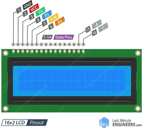
- GND: This pin is the ground connection.
- VCC: It provides power to the LCD and is usually connected to 5 volts.
- Vo (LCD Contrast): This pin controls the contrast of the LCD. By utilizing a voltage divider network and a potentiometer, we can achieve precise contrast adjustments.
- RS (Register Select): This pin differentiates between commands (e.g., setting the cursor position, clearing the screen) and data. When sending commands, the RS pin is set to LOW, and when sending data, it is set to HIGH.
- R/W (Read/Write): This pin allows reading data from or writing data to the LCD. As the LCD is primarily used as an output device, this pin is usually held low, forcing the LCD into WRITE mode.
- E (Enable): This pin is used to enable the display. When set to LOW, the LCD ignores activity on the R/W, RS, and data bus lines. When set to HIGH, the LCD processes incoming data.
- D0-D7 (Data Bus): These pins carry the 8-bit data sent to the display. For instance, to display an uppercase ‘A’ character, we set these pins to 0100 0001 according to the ASCII table.
- A-K (Anode & Cathode): These pins control the backlight of the LCD.
Testing a Character LCD 16×2 Arduino
Now it’s time for the exciting part: testing the LCD.
To begin, connect the Arduino’s 5V and GND pins to the power rail on the breadboard and insert the LCD into the breadboard.
The LCD requires two separate power connections: one for the LCD itself (pins 1 and 2) and one for the LCD backlight (pins 15 and 16). Connect LCD pins 1 and 16 to GND, and pins 2 and 15 to 5V.
Depending on the manufacturer, some LCDs may include a current-limiting resistor for the backlight. You can find it on the back of the LCD, near pin 15. If your LCD doesn’t have this resistor or if you’re uncertain, you’ll need to add one between 5V and pin 15. A 220-ohm resistor should be sufficient, although it may slightly dim the backlight. For better results, consult the datasheet to determine the maximum backlight current and select an appropriate resistor value.
Now let’s connect a potentiometer to the display. This is necessary to finely adjust the display’s contrast for optimal visibility. Connect one end of a 10K potentiometer to 5V, the other end to GND, and connect the middle (wiper) to LCD pin 3.
That’s it! Now power on the Arduino. You’ll see the backlight illuminate. As you turn the knob of the potentiometer, you’ll observe the first row of rectangles appearing. If you’ve reached this stage, congratulations! Your LCD 16×2 Arduino is functioning correctly.
Wiring a 16×2 Character LCD to an Arduino
Let’s complete the wiring of the LCD to the Arduino.
We know that the LCD receives data through eight data pins. However, HD44780-based LCDs are designed in a way that allows us to communicate with them using only four data pins (in 4-bit mode) instead of eight (in 8-bit mode). This helps us save 4 I/O pins!
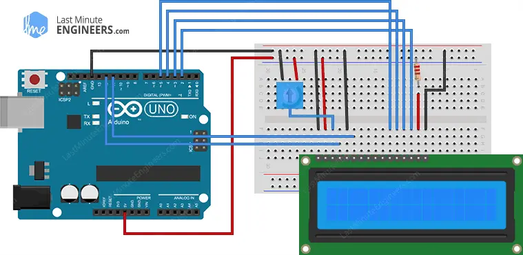
To interface the LCD in 4-bit mode, we only need six pins: RS, EN, D7, D6, D5, and D4.
Connect the LCD’s four data pins (D4-D7) to digital pins 5 to 2 on the Arduino, the EN pin to digital pin 11, and the RS pin to digital pin 12.
The following diagram illustrates the wiring.
In addition to the number of data pins required, there is a significant difference between 4-bit and 8-bit modes when interfacing with an LCD.
8-bit mode is considerably faster compared to 4-bit mode. In 8-bit mode, data can be written in a single operation, whereas in 4-bit mode, a byte is split into two nibbles and two separate write operations are needed.
As a result, 4-bit mode is commonly used to conserve I/O pins. On the other hand, 8-bit mode is ideal when speed is crucial for the application and at least 10 I/O pins are available.
Arduino Example Code
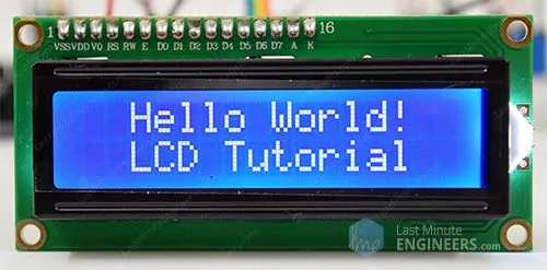
The example sketch below prints “Hello World” to the LCD 16×2 arduino. First, try out the sketch, and then we’ll go over it in detail.
// include the library code:
#include <LiquidCrystal.h>

// Creates an LCD object. Parameters: (rs, enable, d4, d5, d6, d7)
LiquidCrystal lcd(12, 11, 5, 4, 3, 2);

void setup()
{
	// set up the LCD's number of columns and rows:
	lcd.begin(16, 2);

	// Clears the LCD screen
	lcd.clear();
}

void loop()
{
	// Print a message to the LCD.
	lcd.print(" Hello world!");

	// set the cursor to column 0, line 1
	// (note: line 1 is the second row, since counting begins with 0):
	lcd.setCursor(0, 1);
	// Print a message to the LCD.
	lcd.print(" LCD Tutorial");
}
If everything is correct, a “Hello world!” should appear on the display.
Code Explanation
The sketch begins by including the LiquidCrystal library, which allows control of Hitachi HD44780 driver-based LCD displays.
// include the library code:
#include <LiquidCrystal.h>
Next, an object of the LiquidCrystal class is created by specifying the pin numbers to which the LCD’s RS, EN, and four data pins are connected.
// Creates an LCD object. Parameters: (rs, enable, d4, d5, d6, d7)
LiquidCrystal lcd(12, 11, 5, 4, 3, 2);
In the setup, two functions are called. The begin() function initializes the LCD screen interface and specifies the display’s dimensions (columns and rows). For a 16×2 character LCD, the parameters should be 16 and 2; for a 20×4 LCD, the parameters should be 20 and 4.
lcd.begin(16, 2);
lcd.clear();
In the loop, the print() function is used to display “Hello world!” on the LCD. The text should be enclosed in quotation marks. For printing numbers or variables, quotation marks are not necessary.
// Print a message to the LCD.
lcd.print(" Hello world!");
The setCursor() function is then called to move the cursor to the second row. The cursor position determines where the new text will appear on the LCD. The upper-left corner is assumed to be at col=0 and row=0.
lcd.setCursor(0, 1);
lcd.print(" LCD Tutorial");
Other useful functions of the LiquidCrystal Library
The LiquidCrystal library provides several useful functions that can be used with the LiquidCrystal object. Here are some of them:
lcd.home():This function positions the cursor in the upper-left corner of the LCD without clearing the display.
lcd.blink():Use this function to display a blinking block of 5×8 pixels at the cursor’s position where the next character will be written.
lcd.noBlink():To turn off the blinking LCD cursor, use this function.
lcd.cursor():This function displays an underscore (line) at the cursor’s position where the next character will be written.
lcd.noCursor():To hide the LCD cursor, use this function.
lcd.scrollDisplayRight():By using this function, you can scroll the contents of the display one space to the right. If you want continuous scrolling, you can use this function within aforloop.
lcd.scrollDisplayLeft():Similar to the above function, this one scrolls the contents of the display one space to the left. It is also used within aforloop for continuous scrolling.
lcd.noDisplay():This function turns off the LCD display without losing the text currently shown on it.
lcd.display():Use this function to turn on the LCD display after it has been turned off withnoDisplay(). It will restore the text (and cursor) that was on the display.
Creating Custom Characters for a 16×2 Character LCD
If you want to add some uniqueness to your LCD display, you can create your own custom characters or symbols. This is particularly useful when you need to display characters that are not part of the standard ASCII character set.
As mentioned earlier in this tutorial, each character on the LCD is composed of a 5×8 pixel matrix. To define a custom character, you need to specify its pattern within this matrix. The createChar() function is used for this purpose.
To use createChar(), you need to create an array of 8 bytes. Each byte in the array represents a row in the 5×8 matrix. In each byte, the binary digits 0 and 1 determine which pixels in a row should be turned ON or OFF.
All the custom characters you define are stored in the LCD’s CGRAM (Character Generator RAM).
Arduino Example Code
The sketch below demonstrates how to display custom characters on the LCD 16×2 arduino.
// include the library code:
#include <LiquidCrystal.h>
// initialize the library with the numbers of the interface pins
LiquidCrystal lcd(12, 11, 5, 4, 3, 2);
// make some custom characters:
byte Heart[8] = {
0b00000,
0b01010,
0b11111,
0b11111,
0b01110,
0b00100,
0b00000,
0b00000
};
byte Bell[8] = {
0b00100,
0b01110,
0b01110,
0b01110,
0b11111,
0b00000,
0b00100,
0b00000
};
byte Alien[8] = {
0b11111,
0b10101,
0b11111,
0b11111,
0b01110,
0b01010,
0b11011,
0b00000
};
byte Check[8] = {
0b00000,
0b00001,
0b00011,
0b10110,
0b11100,
0b01000,
0b00000,
0b00000
};
byte Speaker[8] = {
0b00001,
0b00011,
0b01111,
0b01111,
0b01111,
0b00011,
0b00001,
0b00000
};
byte Sound[8] = {
0b00001,
0b00011,
0b00101,
0b01001,
0b01001,
0b01011,
0b11011,
0b11000
};
byte Skull[8] = {
0b00000,
0b01110,
0b10101,
0b11011,
0b01110,
0b01110,
0b00000,
0b00000
};
byte Lock[8] = {
0b01110,
0b10001,
0b10001,
0b11111,
0b11011,
0b11011,
0b11111,
0b00000
};
void setup()
{
// initialize LCD and set up the number of columns and rows:
lcd.begin(16, 2);
// create a new character
lcd.createChar(0, Heart);
// create a new character
lcd.createChar(1, Bell);
// create a new character
lcd.createChar(2, Alien);
// create a new character
lcd.createChar(3, Check);
// create a new character
lcd.createChar(4, Speaker);
// create a new character
lcd.createChar(5, Sound);
// create a new character
lcd.createChar(6, Skull);
// create a new character
lcd.createChar(7, Lock);
// Clears the LCD screen
lcd.clear();
// Print a message to the lcd.
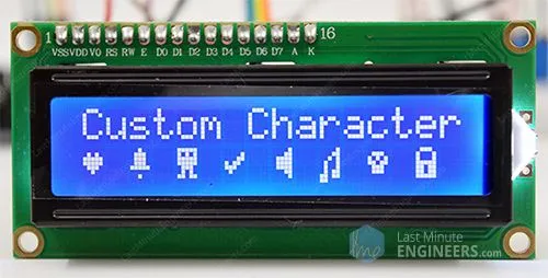
lcd.print("Custom Character");
}
// Print All the custom characters
void loop()
{
lcd.setCursor(0, 1);
lcd.write(byte(0));
lcd.setCursor(2, 1);
lcd.write(byte(1));
lcd.setCursor(4, 1);
lcd.write(byte(2));
lcd.setCursor(6, 1);
lcd.write(byte(3));
lcd.setCursor(8, 1);
lcd.write(byte(4));
lcd.setCursor(10, 1);
lcd.write(byte(5));
lcd.setCursor(12, 1);
lcd.write(byte(6));
lcd.setCursor(14, 1);
lcd.write(byte(7));
}
The output appears as shown.
Code Explanation
After including the library and creating the LCD object, custom character arrays are defined. Each array consists of 8 bytes, representing the rows in a 5×8 matrix.
This sketch includes eight custom characters. For instance, let’s take the Heart[8] array. The arrangement of 0s and 1s forms the shape of a heart, where 0 represents an off pixel and 1 represents an on pixel.
byte Heart[8] = {
0b00000,
0b01010,
0b11111,
0b11111,
0b01110,
0b00100,
0b00000,
0b00000
};
In the setup, we use the createChar() function to define a custom character. This function requires two parameters: a number between 0 and 7 to allocate one of the eight available custom characters, and the name of the array.
// create a new character
lcd.createChar(0, Heart);
In the loop, to display the custom character, we simply use the write() function and provide it with the number of the character we reserved earlier.
// byte(0) represents the Heart character.
lcd.write(byte(0));
Related article
- Step-by-Step Guide: Arduino Integration with I2C LCD Screen
- Arduino LCD Tutorial: How to Interface a 16×2 Character LCD Module
- Using TMP36 Temperature Sensor: Arduino Interfacing Guide
- Mastering Light Sensing: ESP32 and BH1750 Integration Guide
- Arduino RFID Tutorial: Interface RC522 RFID Module and How It Works


