

There are multiple development platforms available for programming the ESP8266. Here are some options:
- Arduino IDE: This platform is suitable for those who are already familiar with Arduino. It provides a user-friendly interface and is a popular choice for beginners.
- Espruino: It is a JavaScript SDK and firmware that closely emulates Node.js. If you are comfortable with JavaScript, Espruino can be a good option for you.
- Mongoose OS: This is an operating system specifically designed for IoT devices. It is recommended by Espressif Systems and Google Cloud IoT for developing IoT applications.
- MicroPython: MicroPython is an implementation of Python 3 for microcontrollers. If you prefer Python as your programming language, MicroPython can be a great choice.
- Espressif SDK: Espressif provides an official SDK that allows you to take full advantage of all the features of the ESP8266. This option provides more flexibility and control but may require more advanced programming knowledge.
Among these platforms, the Arduino IDE is considered the most beginner-friendly. Although it may not be the most optimized platform for ESP8266 development, its familiarity and ease of use make it a popular choice for getting started.
Before you can use the Arduino IDE to program the ESP8266, you need to install the ESP8266 board (also known as the ESP8266 Arduino Core) through the Arduino Board Manager. This guide will provide step-by-step instructions on how to download, install, and test the ESP8266 Arduino Core.
Cores are essential for ensuring compatibility between new microcontrollers and the Arduino IDE, as well as existing sketches and libraries. Arduino is responsible for developing cores for the microcontrollers, specifically the Atmel AVR MCUs, used on their boards.
However, anyone can create a core for their own boards, as long as they adhere to Arduino’s rules and requirements.
Certain development boards may require the installation of an additional core. To facilitate this process, Arduino introduced the Boards Manager as a tool for adding cores to the Arduino IDE.
For detailed instructions on using the Arduino IDE Boards Manager, you can refer to their tutorial.
Parts Required
| Component Name | Buy Now |
| ESP8266 NodeMCU CP2102 | Amazon |
Step 1: Installing or Updating the Arduino IDE
To begin, make sure you have the latest version of the Arduino IDE installed on your computer. If you haven’t already done so, we recommend downloading and installing it from the official Arduino website. Having the latest version ensures compatibility and access to all the necessary tools and features.
Step 2: Installing the USB-to-Serial Bridge Driver
Different ESP8266-based development boards may require specific USB-to-serial bridge drivers for proper functionality. Depending on the board you are using, you may need to install the corresponding driver on your computer. Here are some examples:
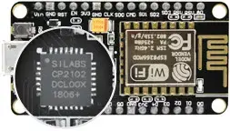
- If you are using the ESP8266 NodeMCU board, it typically utilizes the CP2102 USB-to-serial converter. You will need to install the CP210x USB to UART Bridge VCP drivers.
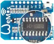
- For the WeMos D1 Mini board, it usually employs the CH340G USB-to-serial converter. In this case, you will need to install the CH340 driver.
It’s important to carefully examine your board to identify the USB-to-serial converter present on it. Once identified, download and install the appropriate driver for that specific converter on your computer. This ensures that your computer can properly communicate with the ESP8266 board.
By following these steps, you will have the Arduino IDE installed or updated, and the necessary USB-to-serial bridge driver installed for your specific ESP8266 board. You will then be ready to proceed with programming and uploading code to your ESP8266 device.
Step 3: Installing the ESP8266 Arduino Core
To install the ESP8266 Arduino Core, follow these steps:
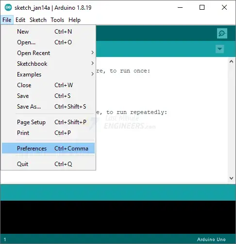
Launch the Arduino IDE and go to File > Preferences.
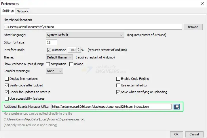
In the Preferences window, locate the “Additional Board Manager URLs” field.
Enter the following URL in the field:
http://arduino.esp8266.com/stable/package_esp8266com_index.json
Click the “OK” button to save the changes.
Next, navigate to Tools > Board > Boards Manager.
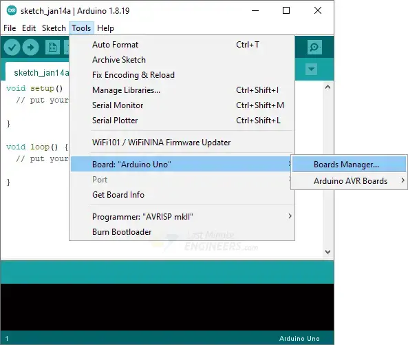
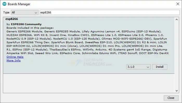
In the Boards Manager window, type “esp8266” in the search bar to filter the results.
Look for the entry labeled “ESP8266 by ESP8266 Community” and click on it.
Click the “Install” button to begin installing the ESP8266 Arduino Core.
Step 4: Selecting the Board and Port
After the ESP8266 Arduino Core is installed, follow these steps:
Restart the Arduino IDE to ensure that the changes take effect.
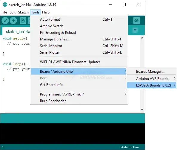
Go to Tools > Board to verify that the ESP8266 boards are now available.
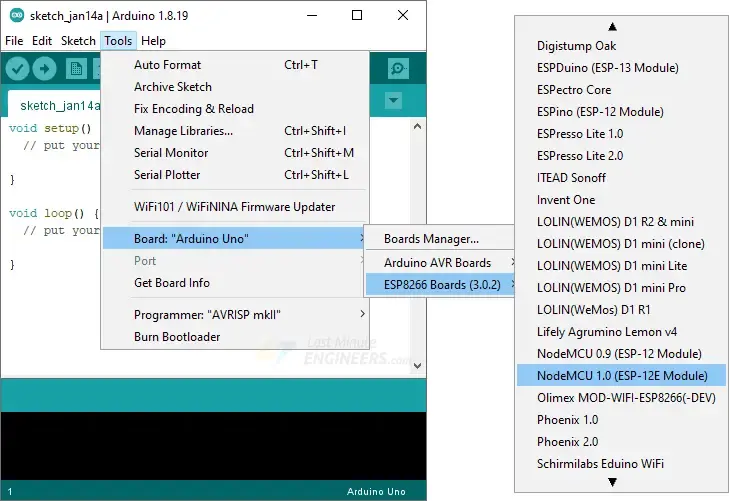
From the Tools > Board menu, select the appropriate board for your project. For example, if you are using the NodeMCU 1.0 (ESP-12E Module), select that option. If you’re unsure about the specific board you have, you can choose the “Generic ESP8266 Module” option.
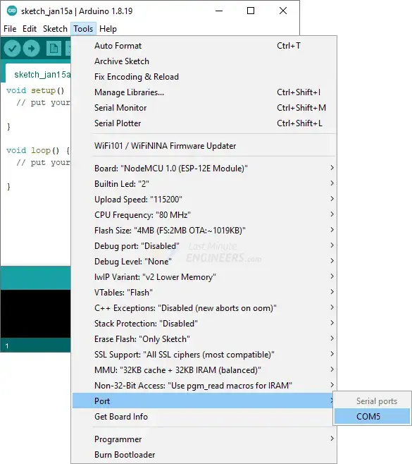
Connect your ESP8266 NodeMCU board to your computer via USB.
In the Tools menu, go to Port and select the appropriate Port to which your ESP8266 board is connected.
That’s it! You have successfully installed the ESP8266 Arduino Core and selected the board and port in the Arduino IDE. You are now ready to write code and program your ESP8266 board using the Arduino IDE.
To do this, go to Tools > Board > Boards Manager in the Arduino IDE, search for ESP8266, and check the installed version. If a newer version is available, make sure to install it.
Step 5: Testing the Installation
After completing the previous steps, it’s time to test your ESP8266 with a simple program. Follow these instructions:
Launch the Arduino IDE. If you had disconnected your board, make sure to plug it back in.
The ESP8266 Arduino core comes with several example sketches that demonstrate different functionalities, such as scanning for nearby networks or building a web server. To access these examples, go to File > Examples > ESP8266.
You will see a list of example sketches. Choose any of them to load the sketch into the Arduino IDE and start experimenting.
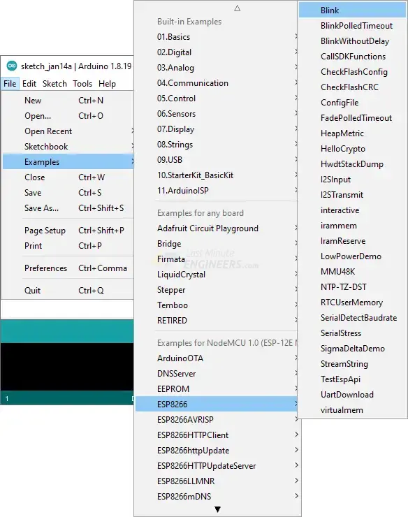
Let’s upload a basic sketch called “Blink.” Go to File > Examples > ESP8266, and open the Blink sketch.
This sketch utilizes the on-board LED, which is available on most ESP8266 development boards. The LED is usually connected to digital pin D0, but the pin number may vary depending on the board.
void setup() {
  pinMode(D0, OUTPUT);
}

void loop() {
  digitalWrite(D0, HIGH);
  delay(500);
  digitalWrite(D0, LOW);
  delay(500);
}
If everything is set up correctly, the on-board LED of your ESP8266 should start blinking. To run the sketch, you may need to press the RST (Reset) button on your ESP8266 board.
Congratulations! You have successfully programmed your first ESP8266 board.
Now you can continue exploring the capabilities of the ESP8266 and develop more complex projects using the Arduino IDE.
ESP8266 Example: WiFi Scan
Let’s proceed with another example sketch for the ESP8266, which showcases how to utilize the ESP8266WiFi library to scan nearby WiFi networks and display the results.
You can find this example by navigating to File > Examples > ESP8266WiFi > WiFiScan.
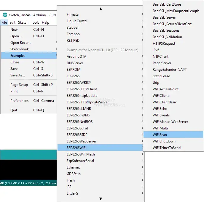
Load the WiFiScan sketch from the example sketches into your Arduino IDE.
#include <ESP8266WiFi.h>

void setup() {
  Serial.begin(115200);
  Serial.println(F("\nESP8266 WiFi scan example"));

  // Set WiFi to station mode
  WiFi.mode(WIFI_STA);

  // Disconnect from an AP if it was previously connected
  WiFi.disconnect();
  delay(100);
}

void loop() {
  String ssid;
  int32_t rssi;
  uint8_t encryptionType;
  uint8_t* bssid;
  int32_t channel;
  bool hidden;
  int scanResult;

  Serial.println(F("Starting WiFi scan..."));

  scanResult = WiFi.scanNetworks(/*async=*/false, /*hidden=*/true);

  if (scanResult == 0) {
    Serial.println(F("No networks found"));
  } else if (scanResult > 0) {
    Serial.printf(PSTR("%d networks found:\n"), scanResult);

    // Print unsorted scan results
    for (int8_t i = 0; i < scanResult; i++) {
      WiFi.getNetworkInfo(i, ssid, encryptionType, rssi, bssid, channel, hidden);

      Serial.printf(PSTR("  %02d: [CH %02d] [%02X:%02X:%02X:%02X:%02X:%02X] %ddBm %c %c %s\n"),
                    i,
                    channel,
                    bssid[0], bssid[1], bssid[2],
                    bssid[3], bssid[4], bssid[5],
                    rssi,
                    (encryptionType == ENC_TYPE_NONE) ? ' ' : '*',
                    hidden ? 'H' : 'V',
                    ssid.c_str());
      delay(0);
    }
  } else {
    Serial.printf(PSTR("WiFi scan error %d"), scanResult);
  }

  // Wait a bit before scanning again
  delay(5000);
}
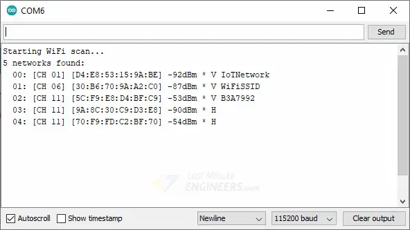
After uploading the sketch, open the serial monitor with a baud rate of 115200 and press the RST (Reset) button on the ESP8266. You should now observe the SSID, RSSI, WiFi channel, and encryption details for each discovered network.
Related article
- Complete ESP8266 Pinout Reference: Simplify Your Hardware Connections
- Mastering ESP8266 GPIO Interrupts: Arduino IDE Configuration Tips
- Get Started: ESP8266 NodeMCU Web Server with Arduino IDE
- DHT11/DHT22 Interface with ESP8266 NodeMCU Web Server: Step-by-Step
- Complete Guide: ESP8266 Over The Air (OTA) Programming with Arduino IDE


