

The ESP8266 has gained significant popularity in the past few years, particularly in IoT and WiFi projects. It is an affordable WiFi module that, with some additional work, can be programmed to function as a standalone web server. This capability adds a fascinating aspect to its functionality.
A web server is a system that stores, processes, and serves web pages to web clients. Web clients, such as web browsers on computers and phones, communicate with web servers using a specialized protocol called Hypertext Transfer Protocol (HTTP).
To illustrate the interaction between a web server and client, the process typically starts with the client sending an HTTP request for a specific web page. The server receives this request and responds by sending back the content of the requested web page. In case the server cannot find the requested page, it will send an error message, commonly known as the “404 Error.”
ESP8266 Operating Modes
The ESP8266 is known for its versatile operating modes, enabling it to connect to existing WiFi networks, act as a web server, and even create its own network for direct device connections and webpage access.
There are three primary modes in which the ESP8266 can operate: Station (STA) mode, Soft Access Point (AP) mode, or a combination of both.
Station (STA) Mode
In Station (STA) mode, the ESP8266 connects to an established WiFi network, typically created by a wireless router.
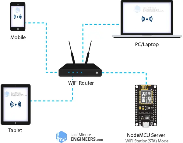
By joining this network, the ESP8266 obtains an IP address assigned by the router. With this IP address, it can set up a web server and serve web pages to all devices connected to the existing WiFi network.
Soft Access Point (AP) Mode
In Soft Access Point (AP) mode, the ESP8266 acts as a hub, creating its own WiFi network similar to a WiFi router. However, unlike a traditional router, it lacks a connection to a wired network. As a result, it can only accommodate up to five connected stations simultaneously.
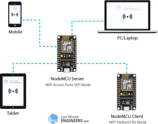
In AP mode, the ESP8266 assigns an SSID (network name) and an IP address to the created WiFi network. It can then serve web pages to all devices connected to this network.
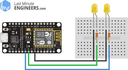
Wiring LEDs to an ESP8266
Now that we grasp the basic concepts of web server functionality and the various modes available for the ESP8266 to create one, let’s proceed with connecting LEDs to the ESP8266 for WiFi-based control.
Start by placing the NodeMCU board on a breadboard, ensuring that each side of the board is on a separate side of the breadboard. Then, connect two LEDs to the digital GPIO pins D6 and D7, utilizing a 220Ω current-limiting resistor.
Once completed, your setup should resemble the image provided.
Parts Required
| Component Name | Buy Now |
| ESP8266 NodeMCU CP2102 | Amazon |
| Breadboard | Amazon |
| 5mm LED Light Diodes | Amazon |
| BOJACK 1000 Pcs 25 Values Resistor Kit 1 Ohm-1M Ohm with 5% 1/4W | Amazon |
Controlling Things via ESP8266 Web Server
You may be curious about how to control devices when the ESP8266 web server solely processes and serves web pages. The solution is quite straightforward – control is achieved by visiting specific URLs.
When you enter a URL in a web browser, it sends an HTTP request (GET request) to a web server. The web server is responsible for handling this request.
For instance, if you enter a URL like http://192.168.1.1/ledon in your browser, it sends an HTTP request to the ESP8266. Upon receiving this request, the ESP8266 recognizes the intention to turn on an LED. Consequently, it activates the LED and sends a dynamic webpage back to the browser, displaying the LED’s status as “on.” This mechanism allows for simple and intuitive control.
Configuring the ESP8266 Web Server in Access Point (AP) mode
Now let’s delve into the exciting part!
This example, as the title suggests, demonstrates how to configure the ESP8266 web server in Access Point (AP) mode, enabling it to serve web pages to any connected client. Connect your ESP8266 to your computer and run the provided sketch to explore the details of this configuration.
#include <ESP8266WiFi.h>
#include <ESP8266WebServer.h>

/* Put your SSID & Password */
const char* ssid = "NodeMCU";  // Enter SSID here
const char* password = "12345678";  //Enter Password here

/* Put IP Address details */
IPAddress local_ip(192,168,1,1);
IPAddress gateway(192,168,1,1);
IPAddress subnet(255,255,255,0);

ESP8266WebServer server(80);

uint8_t LED1pin = D7;
bool LED1status = LOW;

uint8_t LED2pin = D6;
bool LED2status = LOW;

void setup() {
  Serial.begin(115200);
  pinMode(LED1pin, OUTPUT);
  pinMode(LED2pin, OUTPUT);

  WiFi.softAP(ssid, password);
  WiFi.softAPConfig(local_ip, gateway, subnet);
  delay(100);

  server.on("/", handle_OnConnect);
  server.on("/led1on", handle_led1on);
  server.on("/led1off", handle_led1off);
  server.on("/led2on", handle_led2on);
  server.on("/led2off", handle_led2off);
  server.onNotFound(handle_NotFound);

  server.begin();
  Serial.println("HTTP server started");
}
void loop() {
  server.handleClient();
  if(LED1status)
  {digitalWrite(LED1pin, HIGH);}
  else
  {digitalWrite(LED1pin, LOW);}

  if(LED2status)
  {digitalWrite(LED2pin, HIGH);}
  else
  {digitalWrite(LED2pin, LOW);}
}

void handle_OnConnect() {
  LED1status = LOW;
  LED2status = LOW;
  Serial.println("GPIO7 Status: OFF | GPIO6 Status: OFF");
  server.send(200, "text/html", SendHTML(LED1status,LED2status));
}

void handle_led1on() {
  LED1status = HIGH;
  Serial.println("GPIO7 Status: ON");
  server.send(200, "text/html", SendHTML(true,LED2status));
}

void handle_led1off() {
  LED1status = LOW;
  Serial.println("GPIO7 Status: OFF");
  server.send(200, "text/html", SendHTML(false,LED2status));
}

void handle_led2on() {
  LED2status = HIGH;
  Serial.println("GPIO6 Status: ON");
  server.send(200, "text/html", SendHTML(LED1status,true));
}

void handle_led2off() {
  LED2status = LOW;
  Serial.println("GPIO6 Status: OFF");
  server.send(200, "text/html", SendHTML(LED1status,false));
}

void handle_NotFound(){
  server.send(404, "text/plain", "Not found");
}

String SendHTML(uint8_t led1stat,uint8_t led2stat){
  String ptr = "<!DOCTYPE html> <html>\n";
  ptr +="<head><meta name=\"viewport\" content=\"width=device-width, initial-scale=1.0, user-scalable=no\">\n";
  ptr +="<title>LED Control</title>\n";
  ptr +="<style>html { font-family: Helvetica; display: inline-block; margin: 0px auto; text-align: center;}\n";
  ptr +="body{margin-top: 50px;} h1 {color: #444444;margin: 50px auto 30px;} h3 {color: #444444;margin-bottom: 50px;}\n";
  ptr +=".button {display: block;width: 80px;background-color: #1abc9c;border: none;color: white;padding: 13px 30px;text-decoration: none;font-size: 25px;margin: 0px auto 35px;cursor: pointer;border-radius: 4px;}\n";
  ptr +=".button-on {background-color: #1abc9c;}\n";
  ptr +=".button-on:active {background-color: #16a085;}\n";
  ptr +=".button-off {background-color: #34495e;}\n";
  ptr +=".button-off:active {background-color: #2c3e50;}\n";
  ptr +="p {font-size: 14px;color: #888;margin-bottom: 10px;}\n";
  ptr +="</style>\n";
  ptr +="</head>\n";
  ptr +="<body>\n";
  ptr +="<h1>ESP8266 Web Server</h1>\n";
  ptr +="<h3>Using Access Point(AP) Mode</h3>\n";

   if(led1stat)
  {ptr +="<p>LED1 Status: ON</p><a class=\"button button-off\" href=\"/led1off\">OFF</a>\n";}
  else
  {ptr +="<p>LED1 Status: OFF</p><a class=\"button button-on\" href=\"/led1on\">ON</a>\n";}

  if(led2stat)
  {ptr +="<p>LED2 Status: ON</p><a class=\"button button-off\" href=\"/led2off\">OFF</a>\n";}
  else
  {ptr +="<p>LED2 Status: OFF</p><a class=\"button button-on\" href=\"/led2on\">ON</a>\n";}

  ptr +="</body>\n";
  ptr +="</html>\n";
  return ptr;
}
Accessing the Web Server in AP mode
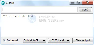
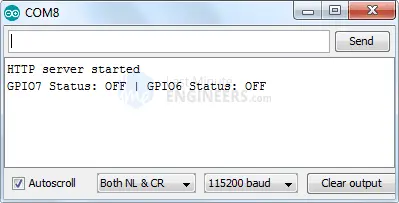
Once you have uploaded the sketch, open the Serial Monitor and set the baud rate to 115200. Press the RESET button on the ESP8266. If everything is working correctly, you will see the message “HTTP server started” displayed.
Now, grab a phone, laptop, or any other WiFi-enabled device and search for a network named “NodeMCU”. Connect to this network using the password “12345678”.
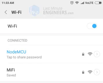
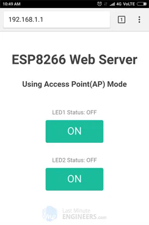
Once you are connected to the NodeMCU AP network, open a web browser and enter the address 192.168.1.1. The ESP8266 will respond by displaying a web page that shows the current status of the LEDs and buttons. You can also monitor the serial monitor to check the status of the ESP8266’s GPIO pins.
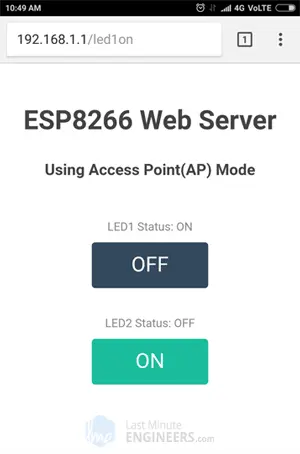
While observing the URL, click the button to turn on LED1. When you click the button, the ESP8266 will receive a request for the /led1on URL. It will then activate LED1 and update the web page with the new LED status. The status of the GPIO pin will also be printed in the serial monitor.
You can test the LED2 button to see if it behaves similarly.
Now, let’s dive into the code to gain a deeper understanding of how it works and learn how to customize it to suit your specific requirements.
Detailed Code Explanation
The sketch starts by including the necessary libraries: ESP8266WiFi.h and ESP8266WebServer.h. These libraries provide specific methods for connecting to the network and configuring the web server without dealing with low-level details.
#include <ESP8266WiFi.h>
#include <ESP8266WebServer.h>
Since we are setting up the ESP8266 web server in Access Point (AP) mode, it will create its own WiFi network. Therefore, we need to specify the SSID, password, IP address, subnet mask, and gateway for the network.
/* Enter your SSID & Password */
const char* ssid = "NodeMCU";
const char* password = "12345678";

/* IP Address configuration */
IPAddress local_ip(192, 168, 1, 1);
IPAddress gateway(192, 168, 1, 1);
IPAddress subnet(255, 255, 255, 0);
After that, we create an instance of the ESP8266WebServer object to access its functions. The constructor takes the port number (80 for HTTP) on which the server will listen. This allows us to connect to the server without specifying the port in the URL.
ESP8266WebServer server(80);
Next, we declare the GPIO pins of NodeMCU to which the LEDs are connected, along with their initial states.
uint8_t LED1pin = D7;
bool LED1status = LOW;

uint8_t LED2pin = D6;
bool LED2status = LOW;
Inside Setup() Function
Inside the setup() function, we configure our HTTP server. First, we establish a serial connection for debugging purposes and configure the GPIO pins to behave as OUTPUT.
Serial.begin(115200);
pinMode(LED1pin, OUTPUT);
pinMode(LED2pin, OUTPUT);
Next, we configure a soft access point to create a Wi-Fi network by providing an SSID, password, IP address, IP subnet mask, and IP gateway.
WiFi.softAP(ssid, password);
WiFi.softAPConfig(local_ip, gateway, subnet);
delay(100);
To handle incoming HTTP requests, we specify the code to be executed when a specific URL is accessed using the server.on() method. This method takes a relative URL path and the name of the function to be executed when that URL is visited.
For example, the following line of code indicates that when the server receives an HTTP request on the root (/) path, it will call the handle_OnConnect() function.
server.on("/", handle_OnConnect);
Similarly, we specify four more URLs to handle the two states of the two LEDs.
server.on("/led1on", handle_led1on);
server.on("/led1off", handle_led1off);
server.on("/led2on", handle_led2on);
server.on("/led2off", handle_led2off);
If the client requests a URL that is not specified with server.on(), the server should respond with a 404 error (Page Not Found). We accomplish this by using the server.onNotFound() method.
server.onNotFound(handle_NotFound);
To start the server, we call the begin() method of the server object.
server.begin();
Serial.println("HTTP server started");
Inside Loop() Function
The loop() function handles the incoming HTTP requests. It uses the handleClient() method of the server object to process the requests. Additionally, it updates the state of the LEDs based on the request.
void loop() {
  server.handleClient();

  if (LED1status) {
    digitalWrite(LED1pin, HIGH);
  } else {
    digitalWrite(LED1pin, LOW);
  }

  if (LED2status) {
    digitalWrite(LED2pin, HIGH);
  } else {
    digitalWrite(LED2pin, LOW);
  }
}
Next, we define the handle_OnConnect() function, which was previously assigned to the root (/) URL using server.on(). In this function, we set the status of both LEDs to LOW (initial state), and print the status on the serial monitor. We respond to the HTTP request using the send() method, passing the HTTP response code, content type, and the content generated by the SendHTML() custom function, which generates a dynamic HTML page with the LED status.
void handle_OnConnect() {
  LED1status = LOW;
  LED2status = LOW;
  Serial.println("GPIO7 Status: OFF | GPIO6 Status: OFF");
  server.send(200, "text/html", SendHTML(LED1status, LED2status));
}
Similarly, we define five more functions to handle requests for turning the LEDs on or off, as well as the 404 error page.
void handle_led1on() {
  LED1status = HIGH;
  Serial.println("GPIO7 Status: ON");
  server.send(200, "text/html", SendHTML(true, LED2status));
}

void handle_led1off() {
  LED1status = LOW;
  Serial.println("GPIO7 Status: OFF");
  server.send(200, "text/html", SendHTML(false, LED2status));
}

void handle_led2on() {
  LED2status = HIGH;
  Serial.println("GPIO6 Status: ON");
  server.send(200, "text/html", SendHTML(LED1status, true));
}

void handle_led2off() {
  LED2status = LOW;
  Serial.println("GPIO6 Status: OFF");
  server.send(200, "text/html", SendHTML(LED1status, false));
}

void handle_NotFound() {
  server.send(404, "text/plain", "Not found");
}
Displaying the HTML Web Page
When the ESP8266 web server receives a request from a web client, the sendHTML() function is called to generate the web page. This function builds a string by concatenating HTML code and returns it to the server.send() function we discussed earlier. The function takes the status of the LEDs as parameters to dynamically generate the HTML content.
The first piece of text we include is the <!DOCTYPE> declaration, which indicates that we are sending HTML code.
String SendHTML(uint8_t led1stat, uint8_t led2stat) {
  String ptr = "<!DOCTYPE html> <html>\n";
Next, we add the <head> section, which includes the <meta> viewport element to make the web page responsive and ensure it looks good on all devices. The <title> tag determines the title of the page.
ptr += "<head><meta name=\"viewport\" content=\"width=device-width, initial-scale=1.0, user-scalable=no\">\n";
ptr += "<title>LED Control</title>\n";
Styling the Web Page
Next, we apply CSS to style the buttons and the overall appearance of the web page. We choose the Helvetica font and set the content to be displayed as inline-block with center alignment.
ptr += "<style>html { font-family: Helvetica; display: inline-block; margin: 0px auto; text-align: center;}\n";
The following code sets the color, font, and margin for the body, H1, H3, and p tags.
ptr += "body{margin-top: 50px;} h1 {color: #444444;margin: 50px auto 30px;} h3 {color: #444444;margin-bottom: 50px;}\n";
ptr += "p {font-size: 14px;color: #888;margin-bottom: 10px;}\n";
We also apply styles to the buttons, including properties such as color, size, margin, and more. The :active selector changes the appearance of the buttons when they are clicked.
ptr += ".button {display: block;width: 80px;background-color: #1abc9c;border: none;color: white;padding: 13px 30px;text-decoration: none;font-size: 25px;margin: 0px auto 35px;cursor: pointer;border-radius: 4px;}\n";
ptr += ".button-on {background-color: #1abc9c;}\n";
ptr += ".button-on:active {background-color: #16a085;}\n";
ptr += ".button-off {background-color: #34495e;}\n";
ptr += ".button-off:active {background-color: #2c3e50;}\n";
Setting the Web Page Heading
After that, we set the heading of the web page. You can modify this text according to your application’s requirements.
ptr += "<h1>ESP8266 Web Server</h1>\n";
ptr += "<h3>Using Access Point(AP) Mode</h3>\n";
Feel free to customize the <h1> and <h3> tags to display the desired heading on your web page.
Displaying the Buttons and Corresponding State
The if statement is used to dynamically display the status of the buttons and LEDs.
if(led1stat) {
  ptr += "<p>LED1 Status: ON</p><a class=\"button button-off\" href=\"/led1off\">OFF</a>\n";
} else {
  ptr += "<p>LED1 Status: OFF</p><a class=\"button button-on\" href=\"/led1on\">ON</a>\n";
}

if(led2stat) {
  ptr += "<p>LED2 Status: ON</p><a class=\"button button-off\" href=\"/led2off\">OFF</a>\n";
} else {
  ptr += "<p>LED2 Status: OFF</p><a class=\"button button-on\" href=\"/led2on\">ON</a>\n";
}
This code dynamically generates HTML content based on the state of the buttons and LEDs. It displays the current status of each LED and provides corresponding buttons to turn them on or off. The CSS classes “button-off” and “button-on” can be used to style the buttons as desired.
Configuring the ESP8266 Web Server in WiFi Station (STA) mode
Now let’s explore the next example, which demonstrates how to configure the ESP8266 web server in Station (STA) mode and serve web pages to any connected client on an existing network.
Before uploading the sketch, you need to make some changes to ensure it works correctly for your network. You must modify the following two variables with your network credentials.
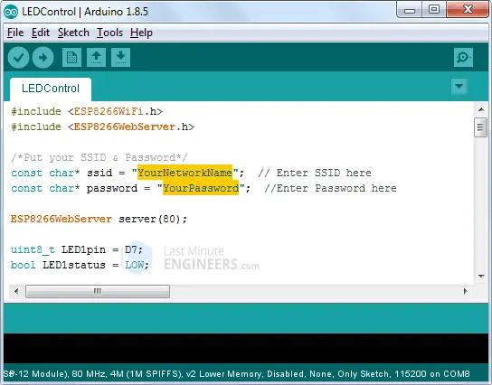
After making the necessary modifications, you can proceed to upload and test the sketch.
#include <ESP8266WiFi.h>
#include <ESP8266WebServer.h>
/*Put your SSID & Password*/
const char* ssid = "YourNetworkName"; // Enter SSID here
const char* password = "YourPassword"; //Enter Password here
ESP8266WebServer server(80);
uint8_t LED1pin = D7;
bool LED1status = LOW;
uint8_t LED2pin = D6;
bool LED2status = LOW;
void setup() {
Serial.begin(115200);
delay(100);
pinMode(LED1pin, OUTPUT);
pinMode(LED2pin, OUTPUT);
Serial.println("Connecting to ");
Serial.println(ssid);
//connect to your local wi-fi network
WiFi.begin(ssid, password);
//check wi-fi is connected to wi-fi network
while (WiFi.status() != WL_CONNECTED) {
delay(1000);
Serial.print(".");
}
Serial.println("");
Serial.println("WiFi connected..!");
Serial.print("Got IP: "); Serial.println(WiFi.localIP());
server.on("/", handle_OnConnect);
server.on("/led1on", handle_led1on);
server.on("/led1off", handle_led1off);
server.on("/led2on", handle_led2on);
server.on("/led2off", handle_led2off);
server.onNotFound(handle_NotFound);
server.begin();
Serial.println("HTTP server started");
}
void loop() {
server.handleClient();
if(LED1status)
{digitalWrite(LED1pin, HIGH);}
else
{digitalWrite(LED1pin, LOW);}
if(LED2status)
{digitalWrite(LED2pin, HIGH);}
else
{digitalWrite(LED2pin, LOW);}
}
void handle_OnConnect() {
LED1status = LOW;
LED2status = LOW;
Serial.println("GPIO7 Status: OFF | GPIO6 Status: OFF");
server.send(200, "text/html", SendHTML(LED1status,LED2status));
}
void handle_led1on() {
LED1status = HIGH;
Serial.println("GPIO7 Status: ON");
server.send(200, "text/html", SendHTML(true,LED2status));
}
void handle_led1off() {
LED1status = LOW;
Serial.println("GPIO7 Status: OFF");
server.send(200, "text/html", SendHTML(false,LED2status));
}
void handle_led2on() {
LED2status = HIGH;
Serial.println("GPIO6 Status: ON");
server.send(200, "text/html", SendHTML(LED1status,true));
}
void handle_led2off() {
LED2status = LOW;
Serial.println("GPIO6 Status: OFF");
server.send(200, "text/html", SendHTML(LED1status,false));
}
void handle_NotFound(){
server.send(404, "text/plain", "Not found");
}
String SendHTML(uint8_t led1stat,uint8_t led2stat){
String ptr = "<!DOCTYPE html> <html>\n";
ptr +="<head><meta name=\"viewport\" content=\"width=device-width, initial-scale=1.0, user-scalable=no\">\n";
ptr +="<title>LED Control</title>\n";
ptr +="<style>html { font-family: Helvetica; display: inline-block; margin: 0px auto; text-align: center;}\n";
ptr +="body{margin-top: 50px;} h1 {color: #444444;margin: 50px auto 30px;} h3 {color: #444444;margin-bottom: 50px;}\n";
ptr +=".button {display: block;width: 80px;background-color: #1abc9c;border: none;color: white;padding: 13px 30px;text-decoration: none;font-size: 25px;margin: 0px auto 35px;cursor: pointer;border-radius: 4px;}\n";
ptr +=".button-on {background-color: #1abc9c;}\n";
ptr +=".button-on:active {background-color: #16a085;}\n";
ptr +=".button-off {background-color: #34495e;}\n";
ptr +=".button-off:active {background-color: #2c3e50;}\n";
ptr +="p {font-size: 14px;color: #888;margin-bottom: 10px;}\n";
ptr +="</style>\n";
ptr +="</head>\n";
ptr +="<body>\n";
ptr +="<h1>ESP8266 Web Server</h1>\n";
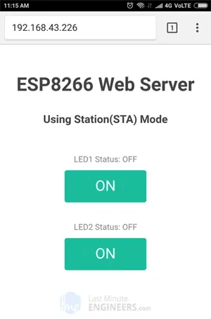
ptr +="<h3>Using Station(STA) Mode</h3>\n";
if(led1stat)
{ptr +="<p>LED1 Status: ON</p><a class=\"button button-off\" href=\"/led1off\">OFF</a>\n";}
else
{ptr +="<p>LED1 Status: OFF</p><a class=\"button button-on\" href=\"/led1on\">ON</a>\n";}
if(led2stat)
{ptr +="<p>LED2 Status: ON</p><a class=\"button button-off\" href=\"/led2off\">OFF</a>\n";}
else
{ptr +="<p>LED2 Status: OFF</p><a class=\"button button-on\" href=\"/led2on\">ON</a>\n";}
ptr +="</body>\n";
ptr +="</html>\n";
return ptr;
}
Accessing the Web Server in STA mode
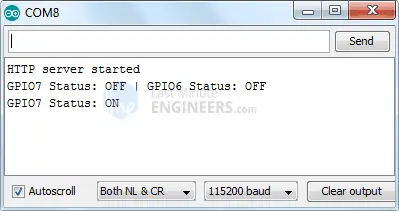
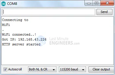
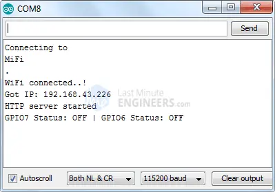
Once you have uploaded the sketch, open the Serial Monitor with a baud rate of 115200. Press the RESET button on the ESP8266. If everything is functioning correctly, the Serial Monitor will display the dynamically assigned IP address obtained from your router, along with the message “HTTP server started.”
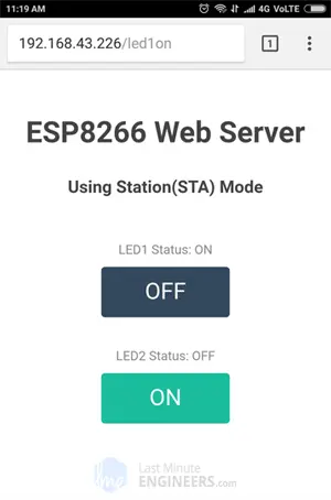
Next, launch a web browser and enter the IP address shown on the serial monitor. The NodeMCU will serve a web page displaying the current status of the LEDs, as well as two buttons for controlling them. You can also monitor the serial monitor to observe the status of the NodeMCU’s GPIO pins.
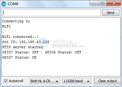
While keeping an eye on the URL, click the button to turn on LED1. When the button is clicked, the ESP8266 will receive a request for the /led1on URL. It will then activate LED1 and update the web page with the updated LED status. The GPIO pin status will also be printed in the serial monitor.
You can test the LED2 button to see if it functions similarly.
Now, let’s examine the code more closely to understand how it works and make any necessary modifications to suit your specific requirements.
Code Explanation
The code presented here is similar to the previous code, with the main difference being that it connects to an existing Wi-Fi network instead of creating its own network using the WiFi.begin() function.
To establish a connection with your local Wi-Fi network, use the following code:
// Connect to your local Wi-Fi network
WiFi.begin(ssid, password);
While the ESP8266 attempts to connect to the network, you can use the WiFi.status() function to check the connectivity status:
// Check if Wi-Fi is connected to the network
while (WiFi.status() != WL_CONNECTED) {
  delay(1000);
  Serial.print(".");
}
The WiFi.status() function returns different statuses, and when the ESP8266 is connected to a Wi-Fi network, it will return WL_CONNECTED.
Once the connection is established, you can use the WiFi.localIP() function to obtain and print the IP address of the ESP8266:
Serial.println("");
Serial.println("WiFi connected..!");
Serial.print("Got IP: ");
Serial.println(WiFi.localIP());
The remaining code for handling HTTP requests, serving web pages, and controlling LEDs in STA mode remains the same as explained in the previous code. This includes declaring the NodeMCU’s GPIO pins, defining server.on() methods to handle HTTP requests, defining the server.onNotFound() method to handle HTTP 404 errors, creating custom functions for specific URLs, generating HTML pages, styling the web page, and displaying buttons with their respective statuses.
Related article
- ESP8266 Sensor Readings: Web Server Auto-Updates via Server-Sent Events
- Real-time Sensor Readings: ESP8266 NodeMCU Web Interface (ESP-NOW + Wi-Fi)
- Seamless Data Gathering: ESP8266 ESP-NOW Receives from Multiple Boards (many-to-one)
- Maximize Communication: ESP8266 ESP-NOW for Multi-Board Data Transfer
- Enhance Connectivity: Two-Way ESP-NOW with ESP8266 NodeMCU
- Maximize Communication: ESP8266 ESP-NOW for Multi-Board Data Transfer
- ESP8266 NodeMCU Email Tutorial: SMTP Server Setup for HTML, Text, and Attachments (Arduino)
- Enhanced Monitoring: Multiple DS18B20s on ESP8266 Web Server


