

In many projects, it is often necessary for the ESP8266 to carry out its regular program while continuously monitoring for specific events. One commonly used solution for this is the utilization of interrupts.
Interrupts can be categorized into two types:
Hardware interrupts: These interrupts occur in response to an external event. For instance, a GPIO interrupt can be triggered when a key is pressed.
Software interrupts: These interrupts occur in response to a software instruction. For example, a simple timer interrupt or a watchdog timer interrupt can be utilized when a timer reaches its timeout.
Parts Required
| Component Name | Buy Now |
| ESP8266 NodeMCU CP2102 | Amazon |
ESP8266 GPIO Interrupt
The ESP8266 allows you to set up GPIO pin interrupts that are triggered when the logic level of a pin changes.
On an ESP8266 board, all GPIO pins, with the exception of GPIO16, can be configured to function as inputs for interrupt requests. This means you can monitor and respond to changes in the state of these pins by utilizing interrupts.
Attaching an Interrupt to a GPIO Pin
To attach an interrupt to a GPIO pin in the Arduino IDE, we utilize the function attachInterrupt(). The syntax for this function is as follows:
attachInterrupt(GPIOPin, ISR, Mode);
The function takes three arguments:
GPIOPin – This sets the GPIO pin as the interrupt pin, specifying which pin the ESP8266 should monitor for interrupts.
ISR – This is the name of the function that will be executed every time the interrupt occurs.
Mode – This parameter determines when the interrupt should be triggered. There are five predefined constants that can be used as valid values for this parameter:
| LOW | Triggers the interrupt whenever the pin is LOW |
| HIGH | Triggers the interrupt whenever the pin is HIGH |
| CHANGE | Triggers the interrupt whenever the pin changes value, from HIGH to LOW or LOW to HIGH |
| FALLING | Triggers the interrupt when the pin goes from HIGH to LOW |
| RISING | Triggers the interrupt when the pin goes from LOW to HIGH |
Interrupt Service Routine
The Interrupt Service Routine (ISR) is a special function that is executed whenever an interrupt event occurs on the GPIO pin.
The syntax for defining an ISR is as follows:
void ICACHE_RAM_ATTR ISR() {
    Statements;
}
ISRs in ESP8266 have certain unique rules compared to other functions:
- ISRs should not have any parameters and should not return any values.
- It is important for ISRs to be concise and efficient to avoid blocking normal program execution.
- According to the ESP8266 documentation, ISRs should be annotated with the ICACHE_RAM_ATTR attribute.
ICACHE_RAM_ATTR is an attribute used in ESP8266 programming to indicate that a specific function or code block should be placed in the ESP8266’s internal RAM (IRAM) instead of the Flash memory. The IRAM is much faster to access compared to Flash memory.
In the context of Interrupt Service Routines (ISRs), using ICACHE_RAM_ATTR ensures that the ISR code is stored in the IRAM. Since ISRs need to be executed as quickly as possible in response to an interrupt, placing them in the faster IRAM allows for faster execution and reduces the potential for timing issues or delays that could occur if the code had to be loaded from Flash memory.
By using ICACHE_RAM_ATTR, developers can optimize the performance of their ISR code and ensure timely execution when handling interrupts on the ESP8266 platform.
Hardware Hookup
Let’s move from theory to practice and set up a practical example.
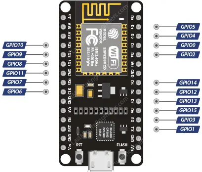
To begin, we will connect a push button to GPIO#12 (D6) on the ESP8266. No external pull-up resistor is required for this pin, as we will enable the internal pull-up resistor.
Example Code: Simple Interrupt
Here’s an example code that showcases the usage of interrupts and provides a proper structure for writing an interrupt service routine.
The code monitors GPIO#12 (D6) for a FALLING edge, indicating a transition from logic HIGH to logic LOW when the button is pressed. When this transition occurs, the function isr is executed. Within this function, a count is incremented to keep track of the number of button presses.
struct Button {
  const uint8_t PIN;
  uint32_t numberKeyPresses;
  bool pressed;
};

Button button1 = {D6, 0, false};

void ICACHE_RAM_ATTR isr() {
  button1.numberKeyPresses++;
  button1.pressed = true;
}

void setup() {
  Serial.begin(115200);
  pinMode(button1.PIN, INPUT_PULLUP);
  attachInterrupt(button1.PIN, isr, FALLING);
}

void loop() {
  if (button1.pressed) {
      Serial.printf("Button has been pressed %u times\n", button1.numberKeyPresses);
      button1.pressed = false;
  }
}
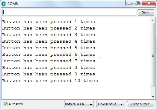
After uploading the sketch to the ESP8266, open the serial monitor with a baud rate of 115200. When you press the button, you will see the following output displayed.
Code Explanation
In the beginning of the sketch, we define a structure called Button. This structure contains three members: the pin number, the number of key presses, and the pressed state. A structure is a collection of variables of different types that are logically related and grouped under a single name.
struct Button {
  const uint8_t PIN;
  uint32_t numberKeyPresses;
  bool pressed;
};
We then create an instance of the Button structure named button1 and initialize its members. The pin number is set to D6, the number of key presses is set to 0, and the default pressed state is set to false.
Button button1 = {D6, 0, false};
The following code defines an interrupt service routine (ISR). As mentioned earlier, ISRs in ESP8266 must have the ICACHE_RAM_ATTR attribute. In this ISR, we simply increment the numberKeyPresses counter by 1 and set the pressed state of the button to true.
void ICACHE_RAM_ATTR isr() {
  button1.numberKeyPresses++;
  button1.pressed = true;
}
In the setup() section of the code, we first initialize the serial communication with the PC using a baud rate of 115200. Then, we enable the internal pull-up resistor for the D6 GPIO pin.
Next, we instruct the ESP8266 to monitor the D6 pin and call the interrupt service routine isr when the pin goes from HIGH to LOW, which is the falling edge.
void setup() {
  Serial.begin(115200);
  pinMode(button1.PIN, INPUT_PULLUP);
  attachInterrupt(button1.PIN, isr, FALLING);
}
In the loop() section of the code, we check if the button has been pressed by examining the pressed state. If the button has been pressed, we print the number of times the key has been pressed so far using Serial.printf(). After that, we set the pressed state of the button to false so that we can continue to receive interrupts.
void loop() {
  if (button1.pressed) {
      Serial.printf("Button has been pressed %u times\n", button1.numberKeyPresses);
      button1.pressed = false;
  }
}
Managing Switch Bounce
Switch bounce is a common problem with interrupts, where they can be triggered multiple times for a single event. In the previous example, you may have noticed that pressing the button once resulted in the counter being incremented multiple times.
To understand why this happens, let’s examine the signal. If you observe the voltage of the pin on a signal analyzer while pressing the button, you will see a signal like this:
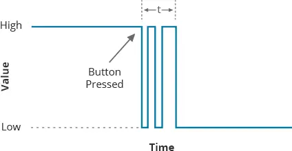
Although it may seem like the contact is made immediately, the mechanical parts inside the button make contact several times before settling into a stable state. This leads to multiple interrupts being triggered.
This mechanical phenomenon is known as switch bounce, similar to how a ball bounces several times before coming to rest after being dropped.
While the time for the signal to stabilize is very fast and almost instantaneous to us, it is a significant period of time for the ESP8266. It can execute multiple instructions during that time, resulting in multiple interrupts being processed.
To eliminate switch bounce, a process called debouncing is used. There are two approaches to achieve this:
- Hardware debouncing: This involves adding an appropriate RC filter to smooth out the transition of the signal.
- Software debouncing: This approach involves temporarily ignoring further interrupts for a short period of time after the first interrupt is triggered. By introducing a delay, subsequent bounces are ignored, allowing the signal to stabilize before considering another interrupt.
Example Code: Debouncing an Interrupt
Below is a modified version of the previous sketch that demonstrates how to debounce an interrupt programmatically. The changes made to the sketch are highlighted in green. With these modifications, the ISR is executed only once for each button press, eliminating the issue of multiple executions.
Please observe the serial output as you press the button. You will notice that the ISR is called only once for each button press.
struct Button {
    const uint8_t PIN;
    uint32_t numberKeyPresses;
    bool pressed;
};

Button button1 = {D6, 0, false};

//variables to keep track of the timing of recent interrupts
unsigned long button_time = 0;
unsigned long last_button_time = 0;

void ICACHE_RAM_ATTR isr() {
    button_time = millis();
if (button_time - last_button_time > 250)
{
        button1.numberKeyPresses++;
        button1.pressed = true;
       last_button_time = button_time;
}
}

void setup() {
    Serial.begin(115200);
    pinMode(button1.PIN, INPUT_PULLUP);
    attachInterrupt(button1.PIN, isr, FALLING);
}

void loop() {
    if (button1.pressed) {
        Serial.printf("Button has been pressed %u times\n", button1.numberKeyPresses);
        button1.pressed = false;
    }
}
//variables to keep track of the timing of recent interrupts unsigned long button_time = 0; unsigned long last_button_time = 0;button_time = millis(); if (button_time - last_button_time > 250) {last_button_time = button_time; }Note: The changes made in the sketch are highlighted in green. Please refer to the modified code above and observe the serial output when pressing the button.

Code Explanation:
The modified code includes a debounce mechanism to ensure that the ISR is executed only once for each button press. Here’s how it works:
- Inside the ISR, a comparison is made between the current time obtained from the
millis()function and the time when the ISR was last called(button1.debounceTime).
- If the time difference is greater than 50 milliseconds, indicating that enough time has passed since the last execution, the code inside the
ifstatement is executed. This includes incrementing the counter(button1.numberKeyPresses), setting the button pressed state to true(button1.pressed), and updating thebutton1.debounceTime with the current time.
- If the time difference is less than 50 milliseconds, it means that the interrupt was triggered too quickly after the previous execution, suggesting a debounce situation. In this case, the code inside the
ifstatement is skipped, and the ESP8266 immediately returns to its normal operation.
- In the
loop()function, the button press is checked by examining thebutton1.pressedvariable. If it is true, indicating a button press has occurred since the last loop iteration, the number of key presses is printed to the serial monitor, and thebutton1.pressedvariable is set back to false.
By using this debounce mechanism, the code ensures that only one execution of the ISR occurs for each button press, preventing multiple triggers due to switch bounce.
Related article
- Step-by-Step Tutorial: Installing ESP8266 Board in Arduino IDE
- Complete Guide: ESP8266 Over The Air (OTA) Programming with Arduino IDE
- Complete ESP8266 Pinout Reference: Simplify Your Hardware Connections


