
If you’re preparing to build your new robot companion, one essential skill to master is controlling DC motors. The most straightforward and cost-effective method for this is by using the L293D Motor Driver IC in conjunction with the Arduino. This versatile IC allows you to manage the speed and direction of two DC motors effortlessly.
Moreover, the L293D Motor Driver IC offers an added advantage—it can also control a unipolar stepper motor such as the 28BYJ-48 or a bipolar stepper motor like the NEMA 17. This flexibility makes it a valuable component for a wide range of motor control applications in your robotic projects.
Controlling a DC Motor
To have precise control over a DC motor, we need to manage both its speed and rotation direction. This can be achieved by combining two fundamental techniques.
PWM – to control speed
The speed of a DC motor can be regulated by altering its input voltage. One commonly used method for this purpose is PWM (Pulse Width Modulation).
PWM involves sending a series of ON-OFF pulses, where the average value of the input voltage is adjusted. The width of these pulses, known as the “Duty Cycle,” determines the average voltage applied to the DC motor.
A higher duty cycle results in a higher average voltage, leading to increased speed, while a shorter duty cycle lowers the average voltage, resulting in decreased speed.
The diagram below illustrates PWM with different duty cycles and their corresponding average voltages.

H-Bridge – to control the rotation direction
The spinning direction of a DC motor can be controlled by changing the polarity of its input voltage. This is typically achieved using an H-bridge circuit.
The H-bridge circuit comprises four switches arranged in an H-like configuration, with the motor placed at the center.
By selectively closing specific switches at a time, the polarity of the voltage applied to the motor can be reversed. This reversal causes the motor to change its spinning direction.
The animation below demonstrates the functioning of the H-bridge circuit, allowing precise control over the rotation direction of the DC motor.
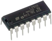
L293D Motor Driver IC
The L293D is a dual-channel H-Bridge motor driver integrated circuit (IC) commonly used in robotics and electronics projects to control DC motors and other inductive loads. It is designed to provide an easy and efficient way to control the speed and direction of two DC motors or a single stepper motor.
The IC comes with four H-Bridge switches that allow it to control the direction of the current flowing through the connected motors. By appropriately activating these switches, the L293D arduino can change the polarity of the voltage applied to the motors, thereby determining their spinning direction. This feature makes it an ideal choice for creating two-wheeled robotic platforms and other motion control systems.
One of the key advantages of the L293D is its capability to handle a wide range of voltages, from 4.5V to 36V, making it compatible with various motor power requirements. Each channel of the driver can deliver a peak output current of up to 1.2A, enabling it to drive small to medium-sized DC motors efficiently.
Furthermore, the L293D includes built-in protection in the form of kick-back diodes. These diodes serve to suppress voltage spikes and protect the IC from potential damage that may occur when a motor is turned off, preventing harmful reverse currents.
Overall, the L293D motor driver IC is a reliable and versatile choice for motor control applications, commonly used in hobbyist and educational projects to add motion and automation to various devices.
Technical Specifications
Here are the specifications:
| Motor output voltage | 4.5V – 36V |
| Logic input voltage | 5V |
| Output Current per channel | 600mA |
| Peak Output Current per Channel | 1.2A |
For more details, please refer below datasheet.
L293D Motor Driver IC Pinout
The L293D IC has a total of 16 pins that connect it to the outside world. The pinout is as follows:
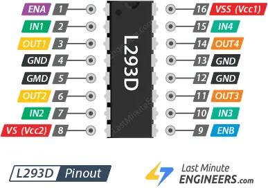
Let’s get acquainted with all the pins one by one.
Power Pins
The L293D motor driver IC has two power-related pins, namely VS and VSS.
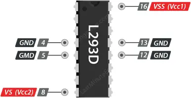
- VS (Vcc2) Pin: This pin provides the power supply to the internal H-Bridge of the L293D IC, which is responsible for driving the connected motors. It is the main power input for the motors. You can connect an input voltage ranging from 4.5V to 36V to this pin. The voltage applied to this pin determines the maximum voltage that the motors can receive.
- VSS (Vcc1) Pin: This pin supplies power to the internal logic circuitry of the L293D IC. It needs to be connected to a stable 5V voltage source. This voltage is used for the operation of the internal control logic within the IC.
Additionally, the L293D IC has multiple GND (Ground) pins. All four GND pins are internally connected and serve as a common ground reference for the IC and the motors. They also help dissipate the heat generated by the IC, especially under high load conditions, ensuring stable operation. Connecting the GND pins properly is essential for the reliable functioning of the motor driver and the connected motors.
Output Pins
The L293D motor driver IC has four output pins, which are used to connect and control the motors. These output pins are divided into two sets, one for each motor (Motor A and Motor B). The pinout is as follows:
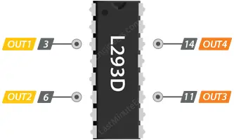
Motor A:
- OUT1: Output 1 for Motor A.
- OUT2: Output 2 for Motor A.
Motor B:
- OUT3: Output 1 for Motor B.
- OUT4: Output 2 for Motor B.
Each pair of output pins (OUT1 and OUT2 for Motor A, and OUT3 and OUT4 for Motor B) are used to drive a DC motor connected to the L293D IC. These pins control the direction of rotation and the speed of the motors.
By providing appropriate logic levels (HIGH or LOW) to these output pins, you can control the H-Bridge circuit inside the L293D IC, which, in turn, controls the direction of current flow through the connected motor. Depending on the input signals, the motor can rotate in forward, reverse, or stop states.
The L293D motor driver arduino can handle motors with voltages ranging from 5V to 36V. It is capable of delivering up to 600mA of current to each motor channel. However, the actual current delivered to the motor depends on the system’s power supply and the motor’s characteristics.
When using the L293D IC, it’s important to connect the motors properly to the correct output pins (OUT1/OUT2 for Motor A and OUT3/OUT4 for Motor B) and apply the appropriate control signals to achieve the desired motor rotation and speed.
Direction Control Pins
The L293D motor driver IC has two sets of direction control pins, which are used to control the spinning direction of each motor (Motor A and Motor B). These direction control pins are used to manipulate the switches of the H-Bridge circuit inside the L293D IC, determining the direction of current flow through the connected motors. The pinout for direction control is as follows:
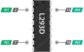
For Motor A:
- IN1: Input 1 for Motor A.
- IN2: Input 2 for Motor A.
For Motor B:
- IN3: Input 1 for Motor B.
- IN4: Input 2 for Motor B.
Each motor has two direction control pins. By applying logic HIGH (5V) or logic LOW (Ground) to these pins, you can control the spinning direction of the respective motor. The table below illustrates how to control the direction using the direction control pins:
| IN1 | IN2 | Spinning Direction |
| Low(0) | Low(0) | Motor OFF |
| High(1) | Low(0) | Forward |
| Low(0) | High(1) | Backward |
| High(1) | High(1) | Motor OFF |
For example, if you set IN1 to HIGH and IN2 to LOW for Motor A, it will spin forward. If you set IN1 to LOW and IN2 to HIGH, it will spin in the reverse direction. Setting both IN1 and IN2 to LOW will stop the motor by applying a brake, and setting both to HIGH will also stop the motor, but this time without braking.
By appropriately configuring the direction control pins for each motor, you can control the rotation direction of your connected DC motors using the L293D motor driver IC.
Speed Control Pins
The L293D motor driver IC has two speed control pins, labeled as ENA and ENB, which are used to enable or disable the motors and control their speed. These pins allow you to adjust the PWM (Pulse Width Modulation) signal to regulate the average voltage applied to the connected motors, thus controlling their speed. The pinout for speed control is as follows:

- ENA: Speed control pin for Motor A.
- ENB: Speed control pin for Motor B.
To control the speed of the motors, you need to apply a PWM signal to these pins. By varying the duty cycle of the PWM signal, you can adjust the average voltage supplied to the motors, which directly affects their speed. The higher the duty cycle, the higher the average voltage, and the faster the motor will spin. Conversely, a lower duty cycle will result in a lower average voltage and slower motor speed.
Typically, you can use the analogWrite() function in Arduino to generate the PWM signal for speed control. The range of duty cycle values is from 0 (0% duty cycle – motor stopped) to 255 (100% duty cycle – maximum speed).
For example, to set the speed of Motor A, you can use the analogWrite() function like this:
analogWrite(ENA, speedValue); // 'speedValue' is the desired duty cycle value (0 to 255).
Similarly, you can set the speed of Motor B using the ENB pin in the same manner.
Keep in mind that the actual speed of the motor will depend on the motor’s characteristics and the applied power supply voltage. The L293D IC can deliver up to 600mA to the motors per channel, but the actual current supplied to the motor will depend on the power supply and the load conditions.
By manipulating the PWM signal on the speed control pins, you can easily control the speed of your connected DC motors using the L293D motor driver IC.
Wiring a L293D Motor Driver IC to an Arduino
Now that we know everything about the IC, we can start connecting it to our Arduino!
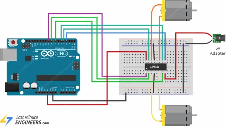
Let’s start by connecting the power supply to the motors. In our experiment we are using DC gearbox motors (also known as ‘TT’ motors) commonly found in two-wheel-drive robots. They are rated for 3 to 12V. Therefore, we will connect the external 5V power supply to the VS (Vcc2) pin.
Next, we need to supply 5V to the logic circuitry of the L293D arduino. Connect the VSS (Vcc1) pin to the 5V output on the Arduino. And make sure your circuit and Arduino share a common ground.
Now connect the L293D IC’s Input and Enable pins (ENA, IN1, IN2, IN3, IN4 and ENB) to the six Arduino digital output pins (9, 8, 7, 5, 4 and 3). Note that Arduino output pins 9 and 3 are both PWM-enabled.
Finally, connect one motor to OUT1 and OUT2 and the other motor to OUT3 and OUT4. You can interchange the connections of your motor. There is technically no right or wrong way.
When you are done you should have something that looks similar to the illustration shown below.
Parts Required
| Component Name | Buy Now |
| Arduino Uno REV3 | Amazon |
| L293 L293D 16-pin IC Stepper Motor Drivers Controllers | Amazon |
| L293D DC Motor Drive Shield Stepper Motor Drive | Amazon |
| Geared Motor DC3V-12V DC for Four-wheel Drive Toy Car | Amazon |
| Breadboard | Amazon |
| BOJACK 1000 Pcs 25 Values Resistor Kit 1 Ohm-1M Ohm with 5% 1/4W | Amazon |
Arduino Example Code
The following sketch will give you a complete understanding on how to control the speed and spinning direction of a DC motor with the L293D motor driver IC and will serve as the basis for more practical experiments and projects.
// Motor A connections
int enA = 9;
int in1 = 8;
int in2 = 7;
// Motor B connections
int enB = 3;
int in3 = 5;
int in4 = 4;

void setup() {
	// Set all the motor control pins to outputs
	pinMode(enA, OUTPUT);
	pinMode(enB, OUTPUT);
	pinMode(in1, OUTPUT);
	pinMode(in2, OUTPUT);
	pinMode(in3, OUTPUT);
	pinMode(in4, OUTPUT);

	// Turn off motors - Initial state
	digitalWrite(in1, LOW);
	digitalWrite(in2, LOW);
	digitalWrite(in3, LOW);
	digitalWrite(in4, LOW);
}

void loop() {
	directionControl();
	delay(1000);
	speedControl();
	delay(1000);
}

// This function lets you control spinning direction of motors
void directionControl() {
	// Set motors to maximum speed
	// For PWM maximum possible values are 0 to 255
	analogWrite(enA, 255);
	analogWrite(enB, 255);

	// Turn on motor A & B
	digitalWrite(in1, HIGH);
	digitalWrite(in2, LOW);
	digitalWrite(in3, HIGH);
	digitalWrite(in4, LOW);
	delay(2000);

	// Now change motor directions
	digitalWrite(in1, LOW);
	digitalWrite(in2, HIGH);
	digitalWrite(in3, LOW);
	digitalWrite(in4, HIGH);
	delay(2000);

	// Turn off motors
	digitalWrite(in1, LOW);
	digitalWrite(in2, LOW);
	digitalWrite(in3, LOW);
	digitalWrite(in4, LOW);
}

// This function lets you control speed of the motors
void speedControl() {
	// Turn on motors
	digitalWrite(in1, LOW);
	digitalWrite(in2, HIGH);
	digitalWrite(in3, LOW);
	digitalWrite(in4, HIGH);

	// Accelerate from zero to maximum speed
	for (int i = 0; i < 256; i++) {
		analogWrite(enA, i);
		analogWrite(enB, i);
		delay(20);
	}

	// Decelerate from maximum speed to zero
	for (int i = 255; i >= 0; --i) {
		analogWrite(enA, i);
		analogWrite(enB, i);
		delay(20);
	}

	// Now turn off motors
	digitalWrite(in1, LOW);
	digitalWrite(in2, LOW);
	digitalWrite(in3, LOW);
	digitalWrite(in4, LOW);
}
Code Explanation:
The code begins by declaring six variables to store the Arduino pins connected to the L293D motor driver IC. The pins are labeled as enA, in1, in2 for Motor A and enB, in3, in4 for Motor B.
// Motor A connections
int enA = 9;
int in1 = 8;
int in2 = 7;
// Motor B connections
int enB = 3;
int in3 = 5;
int in4 = 4;
In the setup() function, the code sets all the motor control pins as OUTPUTs to indicate that these pins will be used to send signals to the motor driver. It also sets the initial state of all these pins to LOW, ensuring that both motors are initially turned off.
void setup() {
	// Set all the motor control pins to outputs
	pinMode(enA, OUTPUT);
	pinMode(enB, OUTPUT);
	pinMode(in1, OUTPUT);
	pinMode(in2, OUTPUT);
	pinMode(in3, OUTPUT);
	pinMode(in4, OUTPUT);

	// Turn off motors - Initial state
	digitalWrite(in1, LOW);
	digitalWrite(in2, LOW);
	digitalWrite(in3, LOW);
	digitalWrite(in4, LOW);
}
The loop() function is the main part of the code that runs repeatedly. In this case, it calls two other functions: directionControl() and speedControl(). It waits for one second (1000 milliseconds) between each function call using delay().
void loop() {
	directionControl();
	delay(1000);
	speedControl();
	delay(1000);
}
The directionControl() function demonstrates the spinning direction control of the motors. The code starts by setting the enable pins (enA and enB) to the maximum PWM value of 255, which means the motors will operate at full speed.
It then sets the direction control pins (in1, in2, in3, in4) in a specific pattern to make the motors spin in one direction for 2 seconds. After that, it changes the pattern to make the motors spin in the opposite direction for another 2 seconds. Finally, it turns off both motors by setting all the direction control pins to LOW.
void directionControl() {
	// Set motors to maximum speed
	// For PWM maximum possible values are 0 to 255
	analogWrite(enA, 255);
	analogWrite(enB, 255);

	// Turn on motor A & B
	digitalWrite(in1, HIGH);
	digitalWrite(in2, LOW);
	digitalWrite(in3, HIGH);
	digitalWrite(in4, LOW);
	delay(2000);

	// Now change motor directions
	digitalWrite(in1, LOW);
	digitalWrite(in2, HIGH);
	digitalWrite(in3, LOW);
	digitalWrite(in4, HIGH);
	delay(2000);

	// Turn off motors
	digitalWrite(in1, LOW);
	digitalWrite(in2, LOW);
	digitalWrite(in3, LOW);
	digitalWrite(in4, LOW);
}
The speedControl() function demonstrates speed control of the motors using PWM. It first sets the direction control pins to make the motors spin in one direction.
It then uses a for loop to gradually increase the PWM value from 0 to 255, effectively accelerating the motors from zero to maximum speed. The delay(20) inside the loop creates a small delay between each increase, controlling the acceleration rate.
After reaching maximum speed, the code enters another for loop to gradually decrease the PWM value from 255 back to 0, effectively decelerating the motors. Again, the delay(20) creates a small delay between each decrease, controlling the deceleration rate.
Finally, it turns off both motors by setting all the direction control pins to LOW.
By combining direction control and speed control techniques, this code provides a comprehensive example of how to control the DC motors using the L293D motor driver IC with an Arduino. You can modify and expand this code to suit various motor control applications in your projects.
void speedControl() {
	// Turn on motors
	digitalWrite(in1, LOW);
	digitalWrite(in2, HIGH);
	digitalWrite(in3, LOW);
	digitalWrite(in4, HIGH);

	// Accelerate from zero to maximum speed
	for (int i = 0; i < 256; i++) {
		analogWrite(enA, i);
		analogWrite(enB, i);
		delay(20);
	}

	// Decelerate from maximum speed to zero
	for (int i = 255; i >= 0; --i) {
		analogWrite(enA, i);
		analogWrite(enB, i);
		delay(20);
	}

	// Now turn off motors
	digitalWrite(in1, LOW);
	digitalWrite(in2, LOW);
	digitalWrite(in3, LOW);
	digitalWrite(in4, LOW);
}
Related article
- Servo Motor Basics: How It Works and Arduino Interface Guide
- Interfacing DC Motors with Arduino using L298N Motor Driver Module
- Interfacing 28BYJ-48 Stepper Motor Arduino using ULN2003 Driver
- Step-by-Step Guide: Arduino Stepper Motor Control with DRV8825 Driver
- Step-by-Step Guide: Arduino Stepper Motor Control with A4988 Driver
- Arduino Motor Control: DRV8833 Motor Driver for DC Motors
- Step-by-Step Guide: L293D Stepper Motor Driver with Arduino


