

For applications involving a single stepper motor, a driver such as the L298N is sufficient. However, if you intend to create your own CNC machine or 3D printer, a dedicated stepper motor driver like the A4988 becomes essential.
The A4988 Stepper Motor Driver is an ideal choice due to its straightforward step motor control and the availability of multiple stepping modes. This makes it perfect for applications that demand precise and reliable control over stepper motor arduino, such as managing the movement of beds, heads, and assemblies in various CNC plotting, milling, and 3D printer designs.
One of the noteworthy features of the A4988 stepper driver is its ability to control the speed and direction of a bipolar stepper motor controller, like the NEMA 17, using just two pins. This simplicity and efficiency further enhance its appeal for intricate projects and applications.
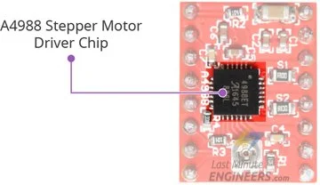
A4988 Stepper Motor Driver Chip
The A4988 Stepper Motor Driver Chip is a powerful microstepping driver manufactured by Allegro. Despite its compact size (0.8″ x 0.6″), it delivers impressive performance for controlling stepper motors.
The A4988 stepper driver has an output drive capacity of up to 35V and ±2A, making it suitable for precise control of bipolar stepper motors like the NEMA 17, with a maximum output current of 2A per coil.
One of its notable features is the regulated output current, which ensures smooth and noiseless operation of the stepper motor, while also eliminating resonance and ringing issues commonly seen in unregulated stepper driver designs.
The A4988 driver is designed with an integrated translator, simplifying its operation and reducing the required control pins to just two—one for controlling the steps and the other for determining the spinning direction.
Another advantage is its ability to offer five different step resolutions: full-step, half-step, quarter-step, eighth-step, and sixteenth-step. This flexibility allows for precise control over the motor’s movement.
Additionally, the A4988 driver includes crucial protection features like under-voltage, shoot-through, short circuit, overcurrent, and thermal protection. These safety mechanisms ensure reliable and safe operation, protecting both the driver and the connected stepper motor arduino.
Technical Specifications
Here are complete specifications:
| Motor output voltage | 8V – 35V |
| Logic input voltage | 3V – 5.5V |
| Continuous current per phase | 1A |
| Maximum current per phase | 2A |
| Microstep resolution | full, 1/2, 1/4, 1/8 and 1/16 |
For more information, please refer to the datasheet below.
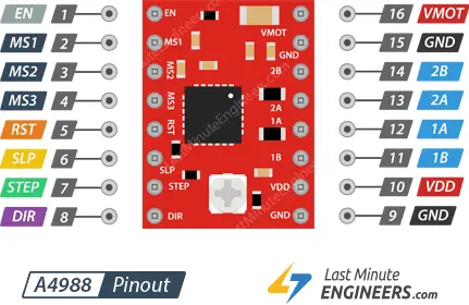
A4988 Motor Driver Pinout
The A4988 motor driver module features a total of 16 pins that facilitate its connections with external components. Let’s explore each pin in detail:
Power Pins
The A4988 arduino requires two distinct power supply connections.
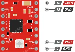
- VDD and GND power the internal logic circuitry, with a voltage range from 3V to 5.5V.
- VMOT and GND provide power to the connected motor, with a voltage range from 8V to 35V.
According to the datasheet, it is essential to have a suitable decoupling capacitor close to the board to sustain a 4A current in the motor supply. Please note that while the board has low-ESR ceramic capacitors onboard, the A4988 stepper driver is only partially protected against voltage spikes. In some cases, these spikes may exceed 35V (the maximum voltage rating of the A4988), which could potentially lead to permanent damage to both the board and the motor. To protect the driver from such spikes, it is advised to include a large 100μF (or at least 47μF) electrolytic capacitor across the motor power supply pins.
Microstep Selection Pins
The A4988 driver supports microstepping, a technique that divides a single step into smaller steps by energizing the coils with intermediate current levels. For instance, when driving the NEMA 17 (with a 1.8° step angle or 200 steps/revolution) in quarter-step mode, the motor will produce 800 microsteps per revolution.
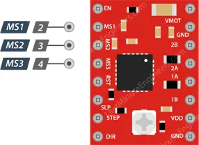
The A4988 driver features three step size (resolution) selector inputs: MS1, MS2, and MS3. By configuring the appropriate logic levels for these pins, you can set the motor to one of five step resolutions.
| MS1 | MS2 | MS3 | Microstep Resolution |
| Low | Low | Low | Full step |
| High | Low | Low | Half step |
| Low | High | Low | Quarter step |
| High | High | Low | Eighth step |
| High | High | High | Sixteenth step |
These three microstep selection pins are pulled LOW by internal pull-down resistors, so if you leave them unconnected, the motor will operate in full step mode.
Control Input Pins
The A4988 motor driver features two essential control inputs: STEP and DIR.
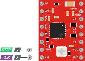
- The STEP input governs the microsteps of the motor. Each HIGH pulse sent to this pin drives the motor with a number of microsteps determined by the microstep selection pins. Increasing the pulse frequency results in a faster motor spin.
- The DIR input controls the spinning direction of the motor. Pulling it HIGH rotates the motor clockwise, while pulling it LOW rotates it counterclockwise. If you desire the motor to turn in only one direction, you can directly connect the DIR pin to either VCC or GND.
Please note that the STEP and DIR pins should not be left floating in your application, as they are not pulled to any specific voltage.
Pins For Controlling Power States
The A4988 arduino offers three distinct inputs for controlling its power states: EN, RST, and SLP.
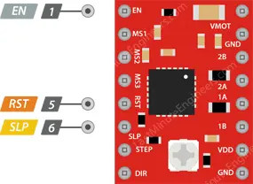
- EN is an active low input pin. When pulled LOW, it enables the A4988 driver. By default, this pin is pulled low, so the driver is always enabled unless you pull it high. This pin is particularly useful for implementing an emergency stop or shutdown system.
- SLP is an active low input pin. Pulling it LOW puts the driver into sleep mode, significantly reducing power consumption when the motor is not in use. It serves as an excellent power-saving feature.
- RST is also an active low input. Pulling this pin LOW disregards all STEP inputs and resets the driver by setting the internal translator to a predefined “home” state. The home state represents the initial position from which the motor starts and varies based on the microstep resolution.
If you’re not using the RST pin, it’s recommended to connect it to an adjacent SLP/SLEEP pin to keep it high and enable the driver. After the wake-up event (logic HIGH on the SLEEP pin), it is advisable to wait 1 millisecond before issuing a Step command to allow the charge pump to stabilize.
Output Pins
The A4988 motor driver module has four output pins for driving a bipolar stepper motor. These pins are labeled as follows:
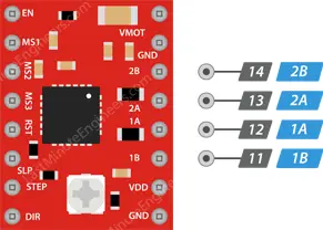
- 1A: This output pin is used to drive one of the coils of the bipolar stepper motor. It provides the current required to energize the coil and move the motor shaft.
- 1B: This output pin is connected to the other coil of the bipolar stepper motor. It works in conjunction with pin 1A to control the motor’s movement and position.
- 2A: Similar to pin 1A, this output pin drives one of the coils of the stepper motor, providing the necessary current to move the motor shaft.
- 2B: This output pin complements pin 2A by connecting to the second coil of the bipolar stepper motor arduino. Together with pin 2A, it controls the motor’s position and rotation.
By providing the appropriate current to these output pins in a specific sequence, the A4988 motor driver can precisely control the movement of the bipolar stepper motor. This allows for accurate and reliable positioning, making it suitable for various applications such as CNC machines, 3D printers, and robotics, where precise motor control is essential.
It’s important to note that each output pin can supply up to 2A of current to the motor. However, the actual current supplied to the motor is determined by factors such as the power supply voltage, cooling system, and current limiting settings of the driver. Properly managing the output pins ensures smooth and efficient operation of the stepper motor arduino with the A4988 stepper driver.
Cooling System – Heatsink
The cooling system of the A4988 driver includes a heatsink. The driver IC can generate significant heat when operating at higher currents, which could lead to potential damage if not properly managed.
To prevent overheating, especially when operating at currents close to the driver’s maximum rating, a heatsink is employed. The heatsink provides a larger surface area for heat dissipation, allowing the driver IC to maintain a safe operating temperature.
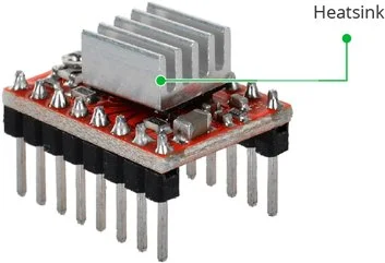
The A4988 driver typically comes with a pre-installed heatsink, which ensures better thermal management during use. It is essential to keep the heatsink in place to ensure the driver’s stable and reliable performance while protecting it from thermal stress.
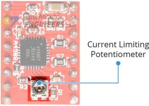
Current limiting
Before operating the motor, it is crucial to set the maximum current flowing through the stepper coils to ensure it stays within the motor’s rated current. The A4988 Stepper Motor Driver simplifies this process with a small trimmer potentiometer dedicated to adjusting the current limit. There are two methods for making this adjustment:
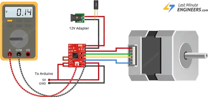
Method 1:
- Refer to your stepper motor’s datasheet and note the rated current (e.g., NEMA 17, 200 steps/rev, 12V, 350mA).
- Set the driver to full-step mode by disconnecting the three microstep selection pins.
- Keep the motor fixed without clocking the STEP input.
- Measure the voltage (Vref) on the metal trimmer potentiometer while adjusting it.
- Use the formula Vref = Current Limit / 2.5 to adjust the Vref voltage. For instance, if your motor’s rated current is 350mA, set the reference voltage to 0.14V. You can easily measure the voltage by connecting one end of an alligator clip test lead to a metal screwdriver’s shank and the other end to your multimeter during the adjustment.
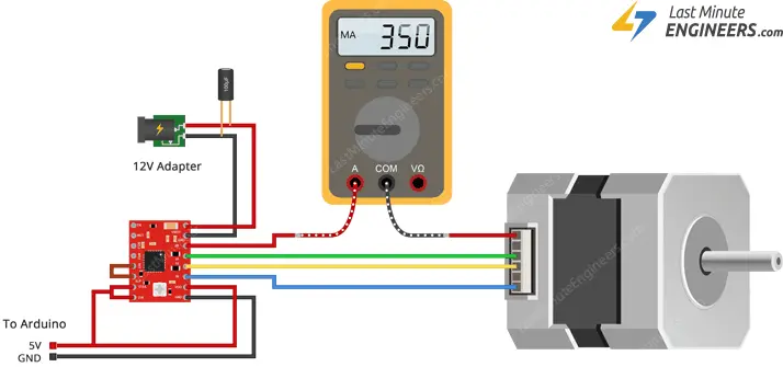
Method 2:
- Refer to your stepper motor’s datasheet and note the rated current (e.g., NEMA 17, 200 steps/rev, 12V, 350mA).
- Set the driver to full-step mode by disconnecting the three microstep selection pins.
- Keep the motor fixed without clocking the STEP input. Instead, connect the STEP input to a logic power supply (5V) to avoid leaving it floating.
- Place the ammeter in series with one of the coils on your stepper motor to measure the actual current flow.
- Use a small screwdriver to adjust the current limit potentiometer until you achieve the rated current.
Remember, if you ever change the logic voltage (VDD), you will need to redo this adjustment to ensure the stepper motor operates safely and efficiently.
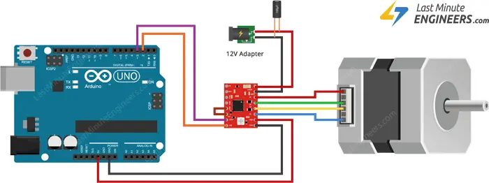
Wiring an A4988 Stepper Motor Driver to an Arduino
To connect an A4988 Stepper Motor Driver to an Arduino, follow these steps:
Connect the VDD pin and GND pin (next to VDD) on the A4988 to the 5V and Ground pins of the Arduino, respectively.
Link the DIR input pin on the A4988 arduino to a digital output pin (e.g., pin 2) on the Arduino. This pin controls the spinning direction of the stepper motor.
Connect the STEP input pin on the A4988 to another digital output pin (e.g., pin 3) on the Arduino. This pin controls the microsteps and determines the motor’s speed.
Connect the stepper motor arduino to the A4988 module using the 2B, 2A, 1A, and 1B pins. The A4988 module is designed to match the 4-pin connector commonly found on bipolar stepper motors, simplifying the connection process.
Avoid attempting to connect or disconnect the stepper motor while the driver is running, as doing so could damage the driver.
To keep the driver enabled, connect the RST pin on the A4988 to the adjacent SLP/SLEEP pin.
If you wish to run the motor in full step mode, leave the microstep selection pins (MS1, MS2, and MS3) disconnected.
Finally, provide power to the motor by connecting the motor power supply to the VMOT and GND pins on the A4988. To prevent voltage spikes, it’s recommended to place a large 100μF decoupling electrolytic capacitor across the motor power supply pins. This will help avoid any potential damage caused by large voltage fluctuations.
Parts Required
| Component Name | Buy Now |
| Arduino Uno REV3 | Amazon |
| A4988 Stepstick Stepper Motor Driver Module | Amazon |
| Nema 17 Stepper Motor Bipolar 2A 59Ncm(84oz.in) | Amazon |
| Breadboard | Amazon |
| BOJACK 1000 Pcs 25 Values Resistor Kit 1 Ohm-1M Ohm with 5% 1/4W | Amazon |
Controlling Bipolar Stepper Motor with A4988 Driver – Code Without Library
The code snippet below demonstrates how to control the speed and spinning direction of a bipolar stepper motor using the A4988 stepper motor driver. It serves as a foundation for practical experiments and projects.
// Define pin connections & motor's steps per revolution
const int dirPin = 2;
const int stepPin = 3;
const int stepsPerRevolution = 200;

void setup()
{
	// Declare pins as Outputs
	pinMode(stepPin, OUTPUT);
	pinMode(dirPin, OUTPUT);
}
void loop()
{
	// Set motor direction clockwise
	digitalWrite(dirPin, HIGH);

	// Spin motor slowly
	for(int x = 0; x < stepsPerRevolution; x++)
	{
		digitalWrite(stepPin, HIGH);
		delayMicroseconds(2000);
		digitalWrite(stepPin, LOW);
		delayMicroseconds(2000);
	}
	delay(1000); // Wait a second

	// Set motor direction counterclockwise
	digitalWrite(dirPin, LOW);

	// Spin motor quickly
	for(int x = 0; x < stepsPerRevolution; x++)
	{
		digitalWrite(stepPin, HIGH);
		delayMicroseconds(1000);
		digitalWrite(stepPin, LOW);
		delayMicroseconds(1000);
	}
	delay(1000); // Wait a second
}
This Arduino sketch controls the bipolar stepper motor by setting the direction (clockwise or counterclockwise) using the dirPin. The stepPin generates pulses to move the motor in discrete steps. The loops inside loop() command the motor to spin slowly and quickly, alternating between clockwise and counterclockwise directions, with delays to control the speed and timing.
Code Explanation:
These lines define the pins used to control the direction and steps of the stepper motor controller. Pin 2 is assigned to dirPin, which sets the spinning direction, and Pin 3 is assigned to stepPin, which generates pulses for the motor steps.
const int dirPin = 2;
const int stepPin = 3;
This constant variable defines the number of steps required for one complete revolution of the stepper motor arduino. It is specific to the motor’s design and varies based on the motor type.
const int stepsPerRevolution = 200;
These lines set stepPin and dirPin as output pins, allowing them to control the stepper motor.
pinMode(stepPin, OUTPUT);
pinMode(dirPin, OUTPUT);
This line sets the direction of the stepper motor to clockwise by setting dirPin HIGH.
digitalWrite(dirPin, HIGH);
This loop controls the slow rotation of the motor in the clockwise direction. It iterates stepsPerRevolution times.
for(int x = 0; x < stepsPerRevolution; x++) {
	digitalWrite(stepPin, HIGH);
	delayMicroseconds(1000);
	digitalWrite(stepPin, LOW);
	delayMicroseconds(1000);
}
Arduino Code – Using AccelStepper library
Controlling a stepper motor without a library is suitable for simple applications with a single motor. However, when dealing with multiple steppers, using a library becomes essential.
For our next experiment, we will employ the powerful AccelStepper library, which offers various features:
- Acceleration and deceleration control for smooth motor movements.
- Simultaneous control of multiple steppers, allowing independent concurrent stepping on each stepper.
Library Installation
Please note that the AccelStepper library is not pre-installed in the Arduino IDE. To use it, follow these steps for library installation:
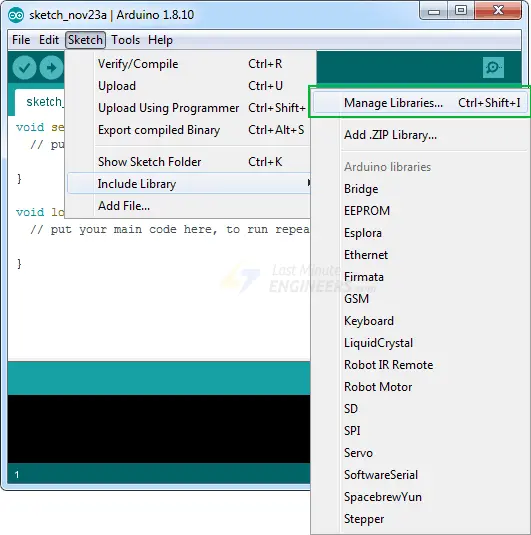
Open the Arduino IDE and go to Sketch > Include Libraries > Manage Libraries…
Wait for the Library Manager to download the library index and update the list of installed libraries.
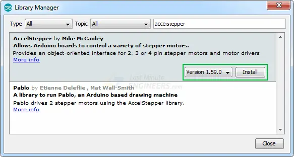
In the search bar, type ‘accelstepper’ to filter the results.
Click on the first entry that appears and then select Install to add the AccelStepper library to your Arduino IDE.
Arduino Code – Accelerating and Decelerating Stepper Motor
Below is a straightforward sketch that demonstrates how to accelerate a stepper motor in one direction, decelerate it to a stop, and then reverse its spinning direction. The process repeats after completing one revolution.
// Include the AccelStepper Library
#include <AccelStepper.h>

// Define pin connections
const int dirPin = 2;
const int stepPin = 3;

// Define motor interface type
#define motorInterfaceType 1

// Creates an instance
AccelStepper myStepper(motorInterfaceType, stepPin, dirPin);

void setup() {
	// set the maximum speed, acceleration factor,
	// initial speed and the target position
	myStepper.setMaxSpeed(1000);
	myStepper.setAcceleration(50);
	myStepper.setSpeed(200);
	myStepper.moveTo(200);
}

void loop() {
	// Change direction once the motor reaches target position
	if (myStepper.distanceToGo() == 0)
		myStepper.moveTo(-myStepper.currentPosition());

	// Move the motor one step
	myStepper.run();
}
This sketch uses the AccelStepper library to control the stepper motor controller. It starts by setting the maximum speed, acceleration, initial speed, and target position. The motor accelerates from the initial speed to the maximum speed while reaching the target position. Once it reaches the target position, it reverses direction and decelerates to a stop before repeating the process. The loop() function continuously checks the motor’s position and moves it one step accordingly using the run() function provided by the AccelStepper library.
Code Explanation:
This line includes the AccelStepper library, which provides functions to control the stepper motor arduino with acceleration and deceleration.
#include <AccelStepper.h>
These lines define the digital pins on the Arduino board that are connected to the DIR (direction) and STEP input pins of the stepper motor driver module.
// Define pin connections
const int dirPin = 2;
const int stepPin = 3;
This line defines the type of motor interface to be used. The value 1 corresponds to the motor driver module used in this example.
// Define motor interface type
#define motorInterfaceType 1
This line creates an instance of the AccelStepper class named myStepper. It takes three arguments: the motor interface type, the STEP pin, and the DIR pin.
AccelStepper myStepper(motorInterfaceType, stepPin, dirPin);
In the setup() function, we configure the stepper motor’s parameters:
-
setMaxSpeed(1000):Sets the maximum speed of the motor in steps per second. The motor will not go faster than this speed during acceleration or deceleration.
setAcceleration(50):Sets the acceleration of the motor in steps per second per second. It determines how quickly the motor reaches its maximum speed.
setSpeed(200):Sets the initial speed of the motor in steps per second.
moveTo(200):Sets the target position of the motor in steps. In this case, it sets the motor to move 200 steps in the forward direction.
void setup() {
	myStepper.setMaxSpeed(1000);
	myStepper.setAcceleration(50);
	myStepper.setSpeed(200);
	myStepper.moveTo(200);
}
The loo function is where the main action happens:p()
myStepper.distanceToGo(): This function returns the remaining number of steps for the motor to reach its target position. If it returns0, it means the motor has reached the target position.
myStepper.moveTo(-myStepper.currentPosition()): When the motor reaches the target position, this line reverses the direction by setting a new target position equal to the negative value of the current position. This effectively makes the motor move in the opposite direction.
myStepper.run(): This function is called repeatedly to make the motor move one step at a time according to the set parameters (acceleration, deceleration, speed). It handles the timing and control of the motor’s motion.
void loop() {
	if (myStepper.distanceToGo() == 0)
		myStepper.moveTo(-myStepper.currentPosition());

	myStepper.run();
}
The sketch will continuously accelerate the motor in one direction until it reaches the target position of 200 steps. Then, it will reverse the direction, decelerate, and come to a stop. This process repeats continuously.
Related article
- Servo Motor Basics: How It Works and Arduino Interface Guide
- Interfacing DC Motors with Arduino using L298N Motor Driver Module
- Interfacing 28BYJ-48 Stepper Motor Arduino using ULN2003 Driver
- Step-by-Step Guide: Arduino Stepper Motor Control with DRV8825 Driver
- Arduino Motor Control: DRV8833 Motor Driver for DC Motors
- Arduino Motor Control: L293D Motor Driver for DC Motors
- Step-by-Step Guide: L293D Stepper Motor Driver with Arduino


