

If your goal is to build a robot and control stepper motors, the L298N motor driver is an affordable and straightforward option. It enables you to control the speed and spinning direction of bipolar stepper motors, including the NEMA 17, which is commonly used in small to medium-sized applications.
However, if you plan to control multiple stepper motor arduino, it is advisable to use a dedicated stepper motor driver like the A4988. This type of driver is designed specifically for stepper motor controller and provides self-contained functionality for controlling multiple motors simultaneously.
To learn more about using the A4988 stepper motor driver, you can refer to a tutorial that provides detailed instructions and information.
Using an H-Bridge to Control a Stepper Motor
An H-Bridge is a crucial component used to control the movement of a stepper motor. It consists of four switches arranged in an “H” configuration, with the stepper motor placed at the center. Each pair of switches corresponds to one of the electromagnetic coils within the stepper motor.
By selectively energizing the coils in a specific sequence, the L298N H-Bridge can control the rotation and movement of the stepper motor. This sequence determines the direction and number of steps the motor takes.
For example, to make the stepper motor rotate in one direction, the H-Bridge energizes the coils in a specific order, causing the motor to move in precise steps. To reverse the rotation, the sequence of energizing the coils is altered, leading to the stepper motor turning in the opposite direction.
The H-Bridge allows for precise control over the stepper motor’s movement, enabling applications that require accurate positioning, such as robotics, CNC machines, and 3D printers. It plays a vital role in the functionality of stepper motor systems, offering versatility and efficiency in controlling their motion.
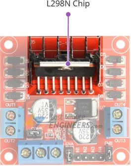
L298N Motor Driver Chip
The L298N Arduino is a motor driver chip developed by STMicroelectronics. It is a versatile integrated circuit capable of controlling DC motors and stepper motor arduino.
Key Features
- Integrated H-Bridge Configuration: The L298N contains two full H-bridges that enable bidirectional control of two DC motors or the precise movement of a single stepper motor arduino.
- Supply Voltage Range: The chip operates within a supply voltage range of 5V to 35V, making it suitable for various power sources.
- Current Capacity: Each L298N H-bridge can handle a continuous current of up to 2A per coil, providing sufficient power for most arduino stepper motor controller.
- Heat Dissipation: The L298N chip is equipped with a heat sink to efficiently manage the generated heat during motor operation.
- Compatibility: It is widely used in robotics, automation, and various projects that involve motor control due to its reliability and performance.
The L298N motor driver chip is a popular choice among hobbyists and engineers for its ability to drive motors smoothly and efficiently.
Technical Specifications
Here are the specifications:
| Motor output voltage | 5V – 35V |
| Motor output voltage (Recommended) | 7V – 12V |
| Logic input voltage | 5V – 7V |
| Continuous current per channel | 2A |
| Max Power Dissipation | 25W |
For more details, please refer below datasheet.
L298N Motor Driver Module Pinout
The L298N motor driver module consists of a total of 11 pins that facilitate connections with external components. Here is a detailed overview of each pin:

Power Pins:
- VS (Motor Power Supply): This pin provides power to the internal H-Bridges of the L298N IC to drive the motor. It accepts an input voltage ranging from 5V to 12V.
- VSS (Logic Power Supply): VSS powers the logic circuitry inside the L298N IC and operates within a voltage range of 5V to 7V.
- GND (Ground): This is the common ground pin that serves as the reference voltage for all other pins.
Output Pins:
The L298N motor driver module features four output channels – OUT1, OUT2, OUT3, and OUT4. These output pins are accessible through two 3.5mm-pitch screw terminals. They are designed to connect to a 12-24V stepper motor arduino.

Each channel on the module is capable of delivering up to 2A of current to the connected stepper motor, with the actual current supplied being determined by the power supply provided to the system.
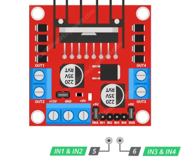
Control Pins:
The module incorporates four control pins, namely IN1, IN2, IN3, and IN4. These control pins allow you to control both the speed and the spinning direction of the arduino stepper motor controller. They are directly responsible for managing the switches in the H-Bridge circuit located inside the L298N chip.
The behavior of the motor is significantly influenced by how these control pins are pulsed:
- The sequence of pulses determines the spinning direction of the motor.
- The frequency of the pulses affects the speed of the motor.
- The number of pulses specifies the distance the motor will turn.
Enable Pins:
The enable pins ENA and ENB are used to enable or disable the motor independently of the input signals.

- Setting these pins HIGH enables the motor.
- Setting these pins LOW disables the motor.
The module typically comes with jumpers attached to these pins. When the jumpers are in place, the motor is enabled. However, if you require finer control over the motor’s operation, you can remove the jumpers and use external signals to manage the motor’s enable state.
On-board 5V Regulator and Jumper
The L298N arduino module features an on-board 5V regulator, known as the 78M05, which can be controlled using a jumper.

When the jumper is inserted, the 5V regulator is enabled, allowing the logic power supply (VSS) to be derived from the motor power supply (VS). In this configuration, the 5V input terminal (VSS) serves as an output pin, delivering a stable 5V with a current rating of 0.5A. This output can be used to power your Arduino or other components requiring a 5V power source.
If the jumper is removed, the 5V regulator is disabled, requiring a separate 5V power supply to be connected to the VSS pin.
If the motor power supply exceeds 12V, it is necessary to remove the jumper to prevent potential damage to the on-board 5V regulator. Additionally, it is crucial not to provide power to both the VSS and VS pins simultaneously when the jumper is in place.
How to Identify the Phases of a Bipolar Stepper Motor?
Identifying the phases of a bipolar stepper motor arduino is essential before connecting it to the module. To do this, you can refer to the motor’s datasheet, which provides detailed information.
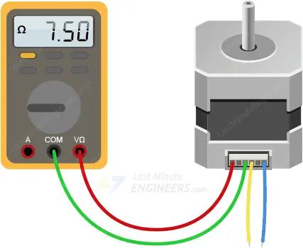
In case the datasheet is unavailable, you can use a simple trick. Set your multimeter to ‘resistance’ mode and measure the resistance between pairs of wires.
If the resistance reads only a few ohms (less than 100Ω), it indicates that you have found a pair of wires.
The remaining two wires will form the second pair.
Wiring a Bipolar Stepper Motor to the L298N Module and Arduino
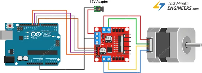
To wire a Bipolar Stepper Motor to the L298N Module and Arduino, follow these steps:
- Connect Power Supply: Use an external 12V power source and connect it to the VS terminal on the L298N module. This voltage is suitable for our NEMA 17 bipolar stepper motor.
- Supply 5V Logic: Keep the 5V-EN jumper in place to enable the on-board 5V regulator, which derives 5V from the motor power supply. This 5V will power the logic circuitry of the L298N arduino.
- Enable the Motor: Make sure both the ENA and ENB jumpers are in place, ensuring that the motor is always enabled.
- Connect Input Pins: Wire the L298N module’s input pins (IN1, IN2, IN3, and IN4) to the corresponding Arduino digital output pins (8, 9, 10, and 11).
- Connect Motor Phases: Connect one phase of the stepper motor to terminal A (OUT1 and OUT2) and the other phase to terminal B (OUT3 and OUT4). Polarity doesn’t matter for the motor phases.
For a visual representation of the wiring setup, please refer to the image below:
Parts Required
| Component Name | Buy Now |
| Arduino Uno REV3 | Amazon |
| L298N Motor Driver controller Board Module Stepper Motor DC Dual H-Bridge for Arduino | Amazon |
| Nema 17 Stepper Motor Bipolar 2A 59Ncm(84oz.in) | Amazon |
| Breadboard | Amazon |
| BOJACK 1000 Pcs 25 Values Resistor Kit 1 Ohm-1M Ohm with 5% 1/4W | Amazon |
Arduino Code – Controlling NEMA 17 Stepper Motor
Below is a simple sketch that controls a bipolar arduino stepper motor controller, such as NEMA 17, using the L298N motor driver. The code makes the motor spin clockwise at 60 RPM and then counterclockwise.
This example will help you understand how to use the Arduino Stepper Library to control the stepper motor arduino and can serve as a starting point for your own practical experiments and projects.
// Include the Arduino Stepper Library
#include <Stepper.h>

// Number of steps per output rotation
const int stepsPerRevolution = 200;

// Create Instance of Stepper library
Stepper myStepper(stepsPerRevolution, 8, 9, 10, 11);


void setup()
{
	// set the speed at 60 rpm:
	myStepper.setSpeed(60);
	// initialize the serial port:
	Serial.begin(9600);
}

void loop()
{
	// step one revolution in one direction:
	Serial.println("clockwise");
	myStepper.step(stepsPerRevolution);
	delay(500);

	// step one revolution in the other direction:
	Serial.println("counterclockwise");
	myStepper.step(-stepsPerRevolution);
	delay(500);
}
This code demonstrates how to control the NEMA stepper motor direction and speed using the Stepper Library, allowing you to build upon it for more complex applications.
Code Explanation:
Here’s an explanation of the provided Arduino code for controlling a NEMA 17 stepper motor using the L298N motor driver:
#include <Stepper.h>
This line includes the Arduino Stepper Library, which provides functions to control stepper motors.
const int stepsPerRevolution = 200;
The variable stepsPerRevolution is set to 200, indicating that the NEMA 17 stepper motor requires 200 steps to complete one full revolution.
Stepper myStepper(stepsPerRevolution, 8, 9, 10, 11);
An instance of the Stepper class is created with the name myStepper, specifying the number of steps per revolution and the pins (8, 9, 10, and 11) to which the L298N motor driver is connected.
void setup()
{
	// set the speed at 60 rpm:
	myStepper.setSpeed(60);
	// initialize the serial port:
	Serial.begin(9600);
}
In the setup() function, the speed of the stepper motor is set to 60 RPM (rotations per minute) using the setSpeed() function of the myStepper instance. The Serial.begin(9600) initializes the serial communication at a baud rate of 9600, which is used for debugging and sending data to the Serial Monitor.
void loop()
{
  Serial.println("Clockwise");
  myStepper.step(stepsPerRevolution);
  delay(500);

  Serial.println("Counterclockwise");
  myStepper.step(-stepsPerRevolution);
  delay(500);
}
In the loop() function, the stepper motor is instructed to rotate one revolution in a clockwise direction using myStepper.step(stepsPerRevolution);. The step() function takes the number of steps as an argument and causes the motor to move accordingly. After one revolution, the motor is then commanded to rotate one revolution in a counterclockwise direction using myStepper.step(-stepsPerRevolution);. The delay(500) functions introduce a 500-millisecond delay between the clockwise and counterclockwise movements, creating a pause between rotations.
Overall, this code demonstrates how to control the direction and speed of a NEMA 17 stepper motor controller using the L298N motor driver and the Arduino Stepper Library. By modifying the speed and number of steps, you can customize the motor’s behavior for various applications.
Related article
- Servo Motor Basics: How It Works and Arduino Interface Guide
- Interfacing DC Motors with Arduino using L298N Motor Driver Module
- Interfacing 28BYJ-48 Stepper Motor Arduino using ULN2003 Driver
- Step-by-Step Guide: Arduino Stepper Motor Control with A4988 Driver
- Step-by-Step Guide: Arduino Stepper Motor Control with DRV8825 Driver
- Arduino Motor Control: DRV8833 Motor Driver for DC Motors
- Arduino Motor Control: L293D Motor Driver for DC Motors
- Step-by-Step Guide: L293D Stepper Motor Driver with Arduino


