
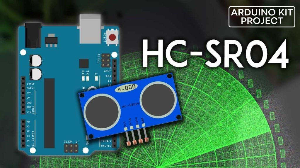
Enhance Your Arduino Project with the HC-SR04 Ultrasonic Distance Sensor to Enable Bat-Like Sensing Abilities. This sensor can accurately measure the distance of objects up to 13 feet away, providing crucial information to prevent collisions or navigate obstacles.
With its low power consumption, cost-effectiveness, and straightforward interface, the HC SR04 Arduino sensor has gained significant popularity among hobbyists and is well-suited for battery-operated devices.
Parts Required
| Component Name | Buy Now |
| Arduino Uno REV3 | Amazon |
| Ultrasonic Sensor Module HC-SR04 | Amazon |
| I2C 1602 LCD Display Module | Amazon |
| Breadboard | Amazon |
HC-SR04 Hardware Overview
The HC-SR04 ultrasonic distance sensor is comprised of two essential components: a transmitter and a receiver. The transmitter is responsible for converting electrical signals into 40 KHz ultrasonic sound pulses, while the receiver detects and listens for these transmitted pulses.
Upon receiving the ultrasonic pulses, the receiver generates an output pulse whose duration is directly proportional to the distance of the object located in front of the sensor.
This versatile sensor offers reliable non-contact range detection, accurately measuring distances from 2 cm to 400 cm (~13 feet) with an impressive precision of 3 mm.
With its 5-volt operating voltage, the HC-SR04 sensor can be easily connected directly to an Arduino or any other microcontroller with 5V logic, simplifying the integration process.
Technical Specifications
Here are the specifications:
| Operating Voltage | DC 5V |
| Operating Current | 15mA |
| Operating Frequency | 40KHz |
| Max Range | 4m |
| Min Range | 2cm |
| Ranging Accuracy | 3mm |
| Measuring Angle | 15 degree |
| Trigger Input Signal | 10µS TTL pulse |
| Dimension | 45 x 20 x 15mm |
HC-SR04 Ultrasonic Sensor Pinout
Let’s take a look at its pinout.
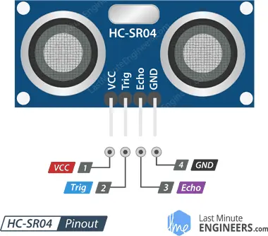
- VCC: The VCC pin of the HC SR04 Arduino ultrasonic sensor is responsible for providing power to the sensor. It can be connected to the 5V output of your Arduino to ensure proper operation.
- Trig (Trigger) Pin: The Trig pin is used to initiate the transmission of ultrasonic sound pulses. To trigger the sensor, you need to set this pin to a HIGH state for a duration of 10µs, which will initiate an ultrasonic burst.
- Echo Pin: The Echo pin of the sensor goes high when the ultrasonic burst is transmitted and remains high until the sensor receives an echo signal. By measuring the duration for which the Echo pin stays high, it is possible to calculate the distance to the object.
- GND: The GND pin is the ground pin of the sensor and should be connected to the ground of the Arduino to establish a common reference voltage between the sensor and the microcontroller.
How Does HC-SR04 Ultrasonic Distance Sensor Work?
The process begins by setting the trigger pin to a HIGH state for a duration of 10µs. As a result, the HC SR04 arduino sensor emits a burst of eight ultrasonic pulses at a frequency of 40 kHz. This specific pattern of eight pulses is designed to allow the receiver to differentiate them from any background ultrasonic noise.
These eight pulses propagate through the air away from the transmitter. At the same time, the echo pin is activated to initiate the reception of the echo-back signal.
If the transmitted pulses are not reflected back, the echo signal will time out and transition to a low state after 38ms (38 milliseconds). This 38ms pulse indicates that there are no obstacles within the range of the sensor.
However, if the transmitted pulses are reflected back, the echo pin will transition to a low state as soon as the signal is received. This generates a pulse on the echo pin, the duration of which varies between 150 µs and 25 ms depending on the time taken to receive the reflected signal.
Calculating the Distance
The width of the received pulse is utilized to determine the distance from the object that caused the reflection. This calculation can be performed using the familiar distance-speed-time equation that we learned in school. To help remember the equation, we can arrange the letters in a triangle.
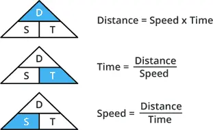
Let’s take an example to illustrate this further. Imagine an object located in front of the sensor at an unknown distance, and we receive a pulse with a width of 500µs on the echo pin. Now, let’s calculate the distance of the object from the sensor using the following equation:
Distance = Speed x Time
In this case, we have the value of time, which is 500µs, and we know the speed. Specifically, it is the speed of sound, which is 340 m/s. To calculate the distance, we need to convert the speed of sound into cm/µs, which is 0.034 cm/μs. Armed with this information, we can now compute the distance.
Distance = 0.034 cm/µs x 500 µs
However, we’re not finished yet! Remember that the echo pulse represents the time it takes for the signal to be transmitted and reflected back. To obtain the actual distance, we need to divide our result by two.
Distance = (0.034 cm/µs x 500 µs) / 2
Distance = 8.5 cm
Thus, we can conclude that the object is positioned 8.5 cm away from the sensor.
Wiring an HC-SR04 Sensor to an Arduino
Now that we have comprehended the functioning of the HC-SR04 ultrasonic sensor, we can proceed to connect it to our Arduino!
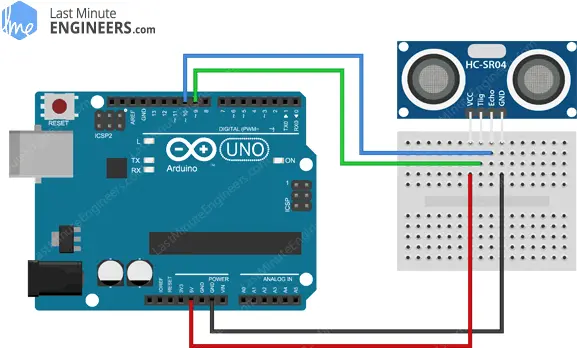
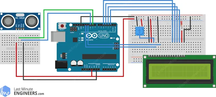
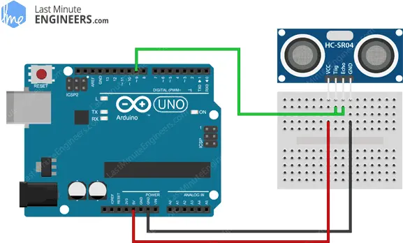
Connecting the HC SR04 Arduino is a straightforward process. Begin by placing the sensor on the breadboard. Establish a connection between the VCC pin of the sensor and the 5V pin on the Arduino. Connect the GND pin of the sensor to the ground pin on the Arduino. Next, connect the trig pin of the sensor to digital pin #9, and the echo pin to digital pin #10.
Refer to the following table for a summary of the pin connections:
| Sensor Pin | Arduino Pin |
|---|---|
| VCC | 5V |
| GND | GND |
| Trig | D9 |
| Echo | D10 |
Once you have completed the connections, your setup should resemble the image depicted below.
Library Installation
Fortunately, we don’t have to go through the tedious process of manually triggering the ultrasonic sensor and measuring the received signal pulse width. Thanks to various libraries available, we can simplify our task. One such popular library is the NewPing library, which we will be using in our examples.
The NewPing library offers advanced features and can handle up to 15 ultrasonic sensors simultaneously. It provides output measurements in centimeters, inches, or time periods, making it highly versatile.
To begin using the NewPing library, you need to install it first. Follow the steps below:
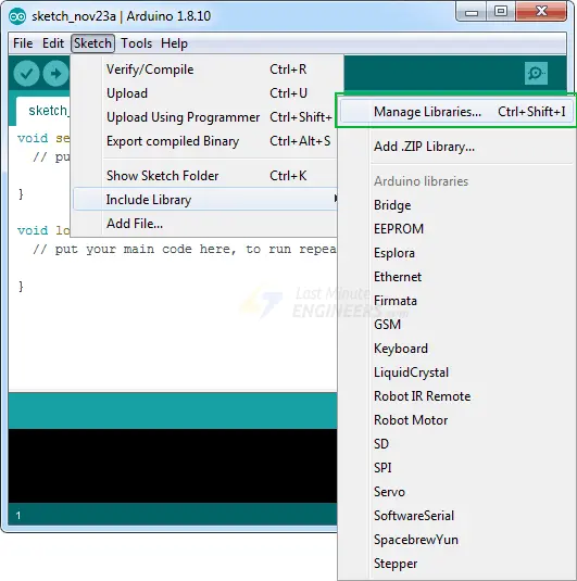
Open the Arduino IDE and navigate to Sketch > Include Libraries > Manage Libraries…
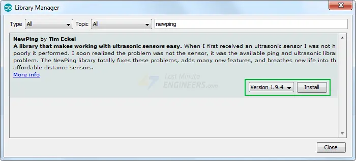
In the search bar, type ‘newping’ to filter the results.
Click on the first entry that appears, and then select Install.
Once the installation is complete, you are ready to utilize the NewPing library’s powerful features in your projects.
Arduino Example Code
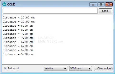
Below is a simple sketch that utilizes the NewPing library to measure distances and display them in centimeters on the serial monitor. Upload this sketch to your Arduino board and follow the instructions to view the measured distances in real-time.
// Include NewPing Library
#include "NewPing.h"

// Hook up HC-SR04 with Trig to Arduino Pin 9, Echo to Arduino pin 10
#define TRIGGER_PIN 9
#define ECHO_PIN 10

// Maximum distance we want to ping for (in centimeters).
#define MAX_DISTANCE 400

// NewPing setup of pins and maximum distance.
NewPing sonar(TRIGGER_PIN, ECHO_PIN, MAX_DISTANCE);

void setup() {
	Serial.begin(9600);
}

void loop() {
	Serial.print("Distance = ");
	Serial.print(sonar.ping_cm());
	Serial.println(" cm");
	delay(500);
}v
After uploading the sketch, follow these steps:
- Open the Arduino IDE and navigate to Tools > Serial Monitor.
- Set the baud rate to 9600 bps (bottom-right corner of the Serial Monitor window).
- Point the ultrasonic sensor towards objects within its range.
- The measured distance in centimeters should start streaming in the Serial Monitor.
Observe the measurements and ensure that they correspond to the distances of the objects. This sketch provides a basic framework for further analysis and customization of the ultrasonic sensor functionality.
Code Explanation:
The sketch starts by including the newly installed NewPing library.
#include "NewPing.h"
In the sketch, we begin by defining the Arduino pins to which the Trig and Echo pins of the HC-SR04 ultrasonic sensor are connected. Additionally, we set a constant called MAX_DISTANCE, which determines the maximum distance for readings. Any readings beyond this distance are considered as “clear” or no ping. By default, MAX_DISTANCE is set to 400 centimeters, but it can be adjusted as needed.
#define TRIGGER_PIN 9
#define ECHO_PIN 10
#define MAX_DISTANCE 400
The line of code NewPing sonar(TRIGGER_PIN, ECHO_PIN, MAX_DISTANCE); creates an instance of the NewPing class named sonar and initializes it with the specified parameters.
The NewPing library provides a simple way to interface with ultrasonic distance sensors, such as the HC SR04 Arduino. To use the library, we need to create an object that represents the sensor and provides methods to perform distance measurements.
NewPing sonar(TRIGGER_PIN, ECHO_PIN, MAX_DISTANCE);
In the setup, we initialize the serial communication with PC.
void setup() {
	Serial.begin(9600);
}
In the loop, we simply call the ping_cm() function and print the result on the serial monitor. This function sends a ping and returns the distance in centimeters.
void loop() {
	Serial.print("Distance = ");
	Serial.print(sonar.ping_cm());
	Serial.println(" cm");
	delay(500);
}
Other useful functions in NewPing Library
There are several useful functions that can be used with the sonar object from the NewPing library.
If you want to obtain the distance in inches instead of centimeters, you can use the sonar.ping_in() function. Here’s an example:
Serial.print(sonar.ping_in());
By default, the sketch provided in the previous code snippet has a resolution of one centimeter. If you want to get the distance in decimal form, you can switch to duration mode instead of distance mode. To do this, you need to change the following line:
Serial.print(sonar.ping_cm());
to:
Serial.print((sonar.ping() / 2) * 0.0343);
Additionally, the NewPing library provides a method called ping_median(iterations) that can improve the accuracy of the HC-SR04 sensor. This method takes multiple measurements, discards out-of-range readings, and then calculates the average of the remaining readings. By default, it takes 5 readings, but you can specify a different number if desired. Here’s an example:
int iterations = 5;
Serial.print((sonar.ping_median(iterations) / 2) * 0.0343);
Using ping_median() with a specified number of iterations can help to enhance the reliability and precision of distance measurements obtained from the HC-SR04 sensor.
Arduino Project – Contactless Distance Finder
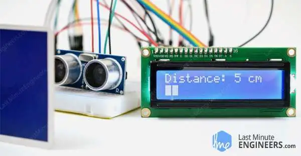
Let’s embark on a brief project to showcase the transformation of a basic ultrasonic sensor into an advanced contactless distance finder. In this project, we will incorporate a 16×2 character LCD that will visually represent the distance from an object using a horizontal bar.
If you are unfamiliar with 16×2 character LCDs, we recommend reading the tutorial provided below to familiarize yourself with their functionality and usage.
Wiring
Next we need to make the connection to the LCD as shown below.
Library Installation
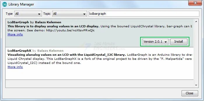
To interface the 16×2 Character LCD Module with Arduino and enable the drawing of a horizontal bar representing the distance to an object, we need to install the LCDBarGraph library.
To install the library, follow these steps:
- Open the Arduino IDE and go to Sketch > Include Libraries > Manage Libraries…
- Wait for the Library Manager to download the library index and update the list of installed libraries.
- In the search bar, type ‘lcdbargraph’ to filter the results.
- Click on the first entry that appears, and then click on the “Install” button to install the library.
Arduino Code
Once you have installed the library, try the below sketch.
// includes the LiquidCrystal Library
#include <LiquidCrystal.h>

// includes the LcdBarGraph Library
#include <LcdBarGraph.h>

// Maximum distance we want to ping for (in centimeters).
#define max_distance 200

// Creates an LCD object. Parameters: (rs, enable, d4, d5, d6, d7)
LiquidCrystal lcd(12, 11, 5, 4, 3, 2);

LcdBarGraph lbg(&lcd, 16, 0, 1); // Creates an LCD Bargraph object.

const int trigPin = 9;
const int echoPin = 10;
long duration;
int distance;

void setup()
{
	lcd.begin(16,2); // Initializes the interface to the LCD screen

	pinMode(trigPin, OUTPUT);
	pinMode(echoPin, INPUT);
}

void loop()
{
	// Write a pulse to the HC-SR04 Trigger Pin
	digitalWrite(trigPin, LOW);
	delayMicroseconds(2);
	digitalWrite(trigPin, HIGH);
	delayMicroseconds(10);
	digitalWrite(trigPin, LOW);

	// Measure the response from the HC-SR04 Echo Pin
	duration = pulseIn(echoPin, HIGH);

	// Determine distance from duration
	// Use 343 metres per second as speed of sound
	distance= duration*0.034/2;

	// Prints "Distance: <value>" on the first line of the LCD
	lcd.setCursor(0,0);
	lcd.print("Distance: ");
	lcd.print(distance);
	lcd.print(" cm");

	// Draws bargraph on the second line of the LCD
	lcd.setCursor(0,1);
	lbg.drawValue(distance, max_distance);
	delay(500);
}
The output looks like this.
Code Explanation:
To interface the 16×2 Character LCD Module with Arduino and utilize the LCDBarGraph library, follow these steps:
Set up the Liquid Crystal Library as you normally would.
Create an instance of LcdBarGraph, referencing the LiquidCrystal instance you just created in the constructor.
// creating bargraph instance
LcdBarGraph lbg(&lcd, 16, 0, 1);
The constructor of LcdBarGraph takes three additional parameters. The second parameter represents the number of the character column in the LCD (in this case, it is 16). The last two parameters are optional and allow for custom positioning of the bar.
After calculating the distance from the sensor, use the drawValue(value, maxValue) function to display the bargraph. This function draws a bargraph with a value between 0 and maxValue, representing the distance.
// display bargraph
lbg.drawValue(distance, max_distance);
By following these steps, you will be able to set up the LCDBarGraph library and display a bargraph representing the distance on the 16×2 Character LCD Module.
Interfacing HC-SR04 with 3-Wire Mode
When you have a limited number of digital I/O pins on your Arduino, you can utilize the 3-pin mode to optimize the usage of pins. Typically, when connecting an HC-SR04 sensor to an Arduino, you would require two I/O pins. However, in 3-wire mode, you only need a single I/O pin instead of two.
In this mode, a single I/O pin serves as both an input and output. This is feasible because the Trig and Echo functionalities are not used simultaneously.
The following table illustrates the pin connections:
| HC-SR04 Pin | Arduino Pin |
|---|---|
| VCC | 5V |
| GND | GND |
| TRIG | Digital 9 |
| ECHO | Digital 9 |
Here is how you can connect the HC-SR04 sensor to an Arduino using 3-wire mode:
Simply connect both the TRIG and ECHO pins of the sensor to digital pin #9 on the Arduino board. Then, define pin 9 for both the TRIGGER_PIN and ECHO_PIN values in the code. The rest of the code remains unchanged.
#define TRIGGER_PIN 9 // Both Trigger and Echo pins connected to pin 9
#define ECHO_PIN 9
By following these instructions, you can utilize the 3-pin mode to connect the HC-SR04 sensor to the Arduino, optimizing the usage of I/O pins.
What are the limitations?
The HC-SR04 ultrasonic sensor is widely regarded for its accuracy and usability, particularly when compared to other low-cost ultrasonic sensors. However, it’s important to note that the HC-SR04 sensor may not work perfectly in all situations. The following scenarios illustrate some limitations of the HC-SR04:
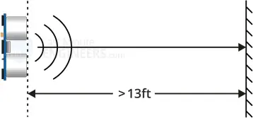
- When the distance between the sensor and the object or obstacle exceeds 13 feet, the sensor may not be able to accurately measure the distance.
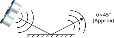
- If the object has a shallow angle or surface that doesn’t reflect sound back to the sensor, the sensor may not receive an echo signal and may not be able to detect the object.
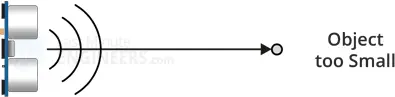
- In the case of small objects, they may not reflect enough sound back to the sensor, especially if the HC-SR04 sensor is mounted low on the device. Additionally, sound may reflect off the floor, potentially affecting the accuracy of the sensor readings.
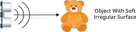
- Certain objects with soft or irregular surfaces, such as stuffed animals, tend to absorb sound rather than reflect it. As a result, the HC-SR04 sensor may encounter difficulties in detecting such objects.
While the HC-SR04 sensor is generally reliable, it’s important to be aware of these limitations and consider them when using the sensor in specific applications or environments.
Related article
- Understanding Accelerometers: Interface ADXL335 with Arduino
- Arduino Soil NPK Sensor: Maximizing Plant Nutrition
- Step-by-Step: Connecting Reed Switch to Arduino
- Track Heart Rate: A Guide to Pulse Sensor and Arduino Integration
- Using TMP36 Temperature Sensor: Arduino Interfacing Guide


