
There are various development platforms available for programming the ESP32. You have the following options:
- Arduino IDE – Designed for users familiar with Arduino programming.
- Espruino – JavaScript SDK and firmware that closely emulates Node.js.
- Mongoose OS – An IoT operating system recommended by Espressif Systems and Google Cloud IoT.
- MicroPython – A Python 3 implementation tailored for microcontrollers.
- Espressif SDK – The official SDK provided by Espressif to leverage all ESP32 features.
Among these platforms, the Arduino IDE is considered the most beginner-friendly. While it may not be the optimal choice for ESP32 development, many people are already acquainted with Arduino, making it easier to get started.
To use the Arduino IDE for ESP32 programming, you need to install the ESP32 board (also known as the ESP32 Arduino Core) through the Arduino Board Manager. This guide will provide step-by-step instructions on how to download, install, and test the ESP32 Arduino Core.
In the context of the Arduino IDE, a core refers to the software package that enables compatibility between the IDE and specific microcontrollers. Cores are necessary to ensure that new microcontrollers can work seamlessly with the Arduino IDE, allowing users to utilize existing sketches and libraries.
Arduino is responsible for developing cores for the microcontrollers (such as Atmel AVR MCUs) used in their boards. However, individuals and organizations can also develop cores for their own microcontroller boards, as long as they adhere to the rules and requirements established by Arduino.
For certain development boards, it may be necessary to install an additional core to enable their use with the Arduino IDE. To simplify this process, Arduino created the Boards Manager, which serves as a tool for adding cores to the Arduino IDE.
If you require more detailed guidance on utilizing the Arduino IDE Boards Manager, Arduino provides a tutorial that offers comprehensive instructions and explanations.
Step 1: Installing or Updating the Arduino IDE
To begin the process of installing the ESP32 Arduino core, it is essential to have the latest version of the Arduino IDE installed on your computer. If you haven’t already done so, we highly recommend installing or updating the Arduino IDE to the most recent version before proceeding.
Step 2: Installing the USB-to-Serial Bridge Driver
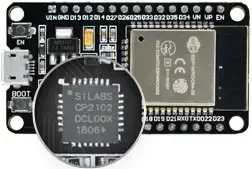
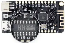
To ensure proper communication between your computer and the ESP32 development board, you may need to install the appropriate USB-to-serial bridge driver. The specific driver required depends on the USB-to-serial converter chip used on your ESP32 board.
Different ESP32 boards utilize different USB-to-serial converters. For example, the CP2102 or CH340G chips are commonly used. It is important to identify the USB-to-serial converter chip on your board before proceeding.
If you have not installed the driver for the USB-to-serial converter on your computer before, follow the instructions provided by the manufacturer to download and install the driver. This will enable your computer to recognize and communicate with the ESP32 board through the USB connection.
Ensure that the USB-to-serial bridge driver is installed correctly before attempting to upload code to your ESP32 board. This will ensure a smooth programming experience and proper functionality of the board.
Step 3: Installing the ESP32 Arduino Core
To utilize the ESP32 with the Arduino IDE, you need to install the ESP32 Arduino Core. Follow these steps to install the core:
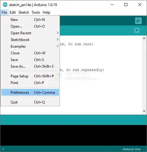
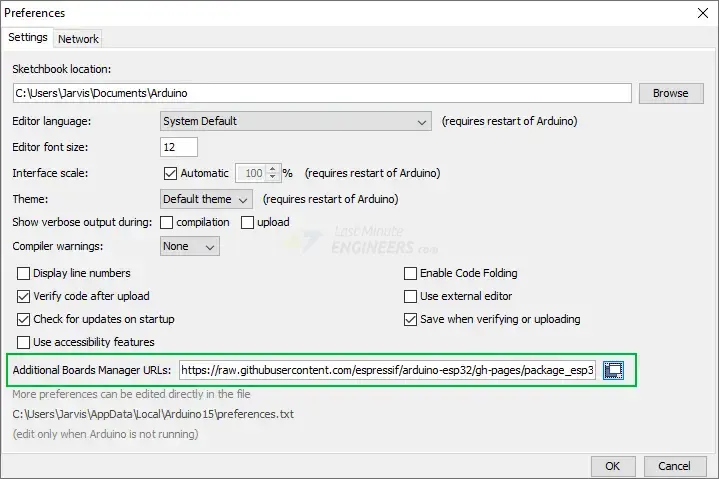
Open the Arduino IDE and go to File > Preferences.
In the Preferences window, locate the “Additional Board Manager URLs” field.
Enter the following URL in the field:
https://raw.githubusercontent.com/espressif/arduino-esp32/gh-pages/package_esp32_index.json
Click the “OK” button to save the changes.
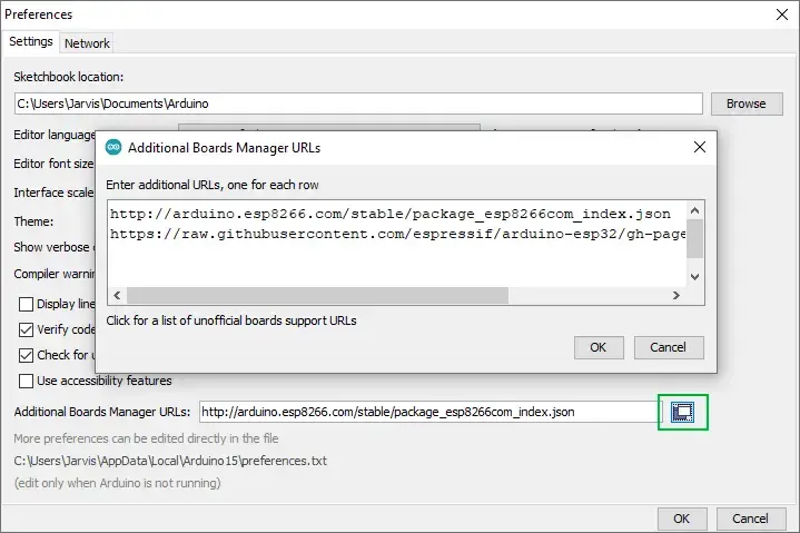
Note: If you have already added URLs for other boards like ESP8266, you can click on the icon next to the field to open a separate window where you can add multiple URLs.
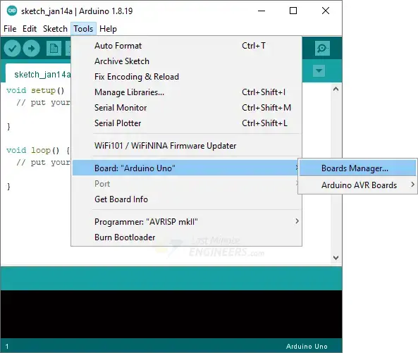
Next, navigate to Tools > Board > Boards Manager…
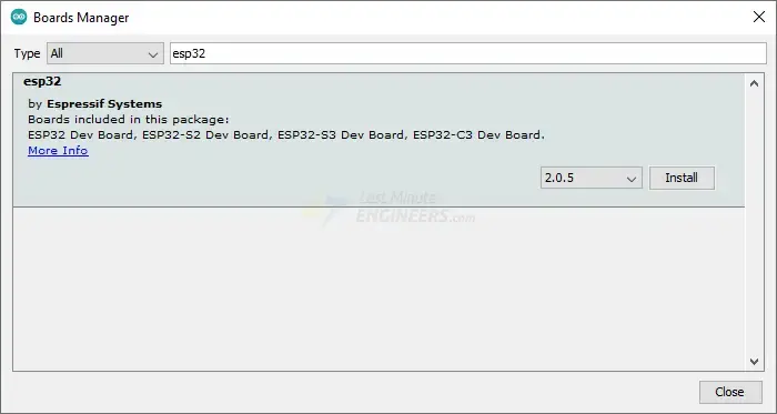
In the Boards Manager window, enter “esp32” in the search bar to filter the results.
Look for “ESP32 by Espressif Systems” in the search results and click on it.
Click the “Install” button to initiate the installation process.
Wait for the installation to finish. Once completed, you have successfully installed the ESP32 Arduino Core in the Arduino IDE. Now you can start developing and uploading code for your ESP32 board.
Step 4: Selecting the Board and Port
After successfully installing the ESP32 Arduino Core, follow these steps to select the board and port settings in the Arduino IDE:
Restart the Arduino IDE to apply the changes made during the installation.
Go to Tools > Board to verify if the ESP32 boards are now listed as available options.
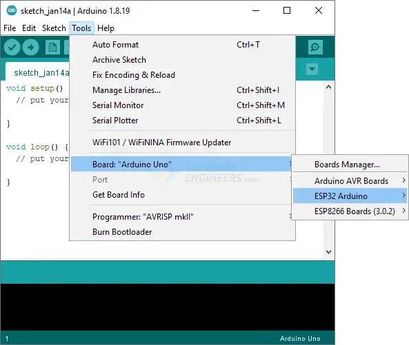
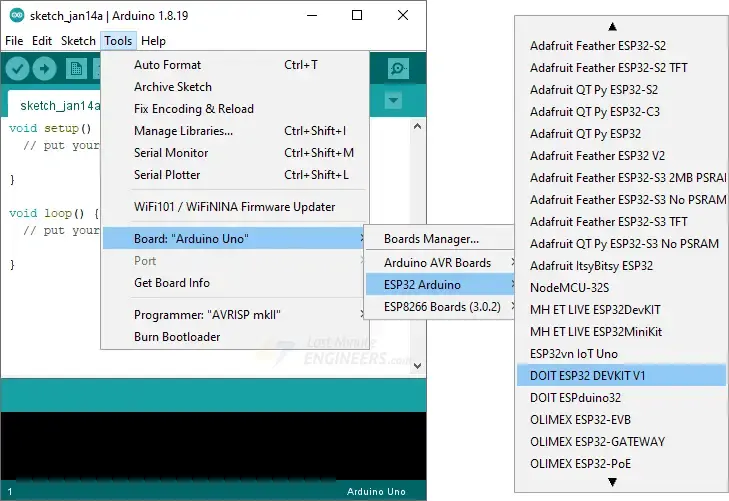
From the Tools > Board menu, select the specific ESP32 board you are using. If you are unsure about the exact board model, you can choose “ESP32 Dev Module” as a general option.
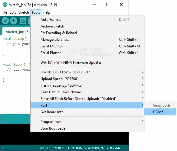
Connect your ESP32 board to your computer using a USB cable.
From the Tools > Port menu, select the appropriate port that corresponds to your connected ESP32 board. The port may vary depending on your operating system.
Once you have selected the board and port, you are ready to start writing code for your ESP32 in the Arduino IDE.
Step 5: Testing the Installation
Now that you have completed the previous steps, it’s time to test your ESP32 installation and upload your first program. Follow these steps:
Launch the Arduino IDE. If you disconnected your ESP32 board, make sure to plug it back in.
Let’s upload a simple sketch called “Blink.” This sketch utilizes the on-board LED that is available on most ESP32 development boards. Please note that the LED pin number may vary depending on your specific board.
int ledPin = 2;

void setup() {
	pinMode(ledPin, OUTPUT);
}

void loop() {
	digitalWrite(ledPin, HIGH);
	delay(500);
	digitalWrite(ledPin, LOW);
	delay(500);
}
If you haven’t already done so, connect your ESP32 board to your computer.
Press the “Upload” button (or go to Sketch > Upload) to upload the sketch to your ESP32 board.
If the upload process is successful, the on-board LED on your ESP32 should start blinking at a regular interval.
To execute the sketch on your ESP32, you may need to press the EN button on your board.
Congratulations! You have successfully programmed your first ESP32 board. Enjoy exploring and developing more projects with your ESP32!
Parts Required
| Component Name | Buy Now |
| ESP32-WROOM-32 Development | Amazon |
More ESP32 Examples
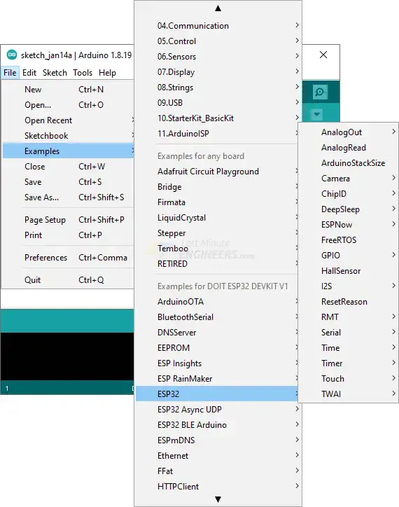
The ESP32 Arduino core offers a wide range of example sketches that demonstrate various functionalities of the ESP32. To access these examples, follow these steps:
Launch the Arduino IDE.
Go to File > Examples > ESP32.
You will see a list of example sketches available for the ESP32.
Choose any example that interests you and load it into the Arduino IDE.
These example sketches cover a wide range of applications, including scanning for nearby networks, working with Bluetooth, using sensors, creating web servers, and more. They provide a great starting point for exploring the capabilities of the ESP32 and experimenting with different functionalities.
Feel free to select any example that catches your attention and start exploring the code to understand how it works.
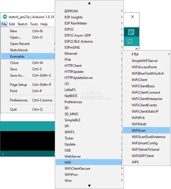
ESP32 Example: WiFi Scan
Let’s try running an ESP32 example sketch that demonstrates how to scan nearby WiFi networks using the WiFi library and print the results.
To access this example, go to File > Examples > WiFi > WiFiScan in the Arduino IDE.
Load the WiFiScan sketch from the examples into your Arduino IDE. The code for the sketch is as follows:
#include "WiFi.h"

void setup()
{
    Serial.begin(115200);

    // Set WiFi to station mode and disconnect from an AP if it was previously connected.
    WiFi.mode(WIFI_STA);
    WiFi.disconnect();
    delay(100);

    Serial.println("Setup done");
}

void loop()
{
    Serial.println("Scan start");

    // WiFi.scanNetworks will return the number of networks found.
    int n = WiFi.scanNetworks();
    Serial.println("Scan done");
    if (n == 0) {
        Serial.println("no networks found");
    } else {
        Serial.print(n);
        Serial.println(" networks found");
        Serial.println("Nr | SSID                             | RSSI | CH | Encryption");
        for (int i = 0; i < n; ++i) {
            // Print SSID and RSSI for each network found
            Serial.printf("%2d",i + 1);
            Serial.print(" | ");
            Serial.printf("%-32.32s", WiFi.SSID(i).c_str());
            Serial.print(" | ");
            Serial.printf("%4d", WiFi.RSSI(i));
            Serial.print(" | ");
            Serial.printf("%2d", WiFi.channel(i));
            Serial.print(" | ");
            switch (WiFi.encryptionType(i))
            {
            case WIFI_AUTH_OPEN:
                Serial.print("open");
                break;
            case WIFI_AUTH_WEP:
                Serial.print("WEP");
                break;
            case WIFI_AUTH_WPA_PSK:
                Serial.print("WPA");
                break;
            case WIFI_AUTH_WPA2_PSK:
                Serial.print("WPA2");
                break;
            case WIFI_AUTH_WPA_WPA2_PSK:
                Serial.print("WPA+WPA2");
                break;
            case WIFI_AUTH_WPA2_ENTERPRISE:
                Serial.print("WPA2-EAP");
                break;
            case WIFI_AUTH_WPA3_PSK:
                Serial.print("WPA3");
                break;
            case WIFI_AUTH_WPA2_WPA3_PSK:
                Serial.print("WPA2+WPA3");
                break;
            case WIFI_AUTH_WAPI_PSK:
                Serial.print("WAPI");
                break;
            default:
                Serial.print("unknown");
            }
            Serial.println();
            delay(10);
        }
    }
    Serial.println("");

    // Delete the scan result to free memory for code below.
    WiFi.scanDelete();

    // Wait a bit before scanning again.
    delay(5000);
}
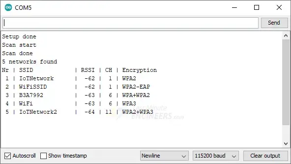
After uploading the sketch, open the serial monitor in the Arduino IDE at a baud rate of 115200 and press the EN button on the ESP32. You should see the SSID, RSSI, WiFi channel, and encryption type for each discovered network.
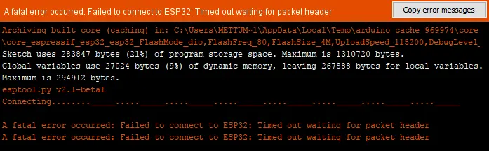
Troubleshooting
If you encounter the “A fatal error occurred: Failed to connect to ESP32… Timed out waiting for packet header…” error when uploading code to your ESP32, it indicates that your board is not in flashing or uploading mode. You can follow the steps below to resolve this issue:
- Press and hold the BOOT button on your ESP32 board.
- Click the Upload button in the Arduino IDE to initiate the sketch upload process.
- Keep holding the BOOT button until you see the message “Writing at 0x00001000… (100%)” in the Arduino IDE log after the “Connecting…” message.
- Release the BOOT button at this point.
- You should now see the “Done uploading” message, indicating that the code has been successfully uploaded.
That’s it! You can now press the EN button on the ESP32 board to restart it and run the newly uploaded sketch.
Please note that you will need to repeat this button sequence every time you want to upload a new sketch to your ESP32.
Related article
- ESP32 Pinout Reference: Simplify Hardware Connections with Ease
- ESP32 Capacitive Touch Pins: Basics for Interactive Projects
- Step-by-Step Tutorial: Setting Up ESP32 Board in Arduino IDE
- Essential ESP32 ADC Basics: Analog-to-Digital Converter Explained


