

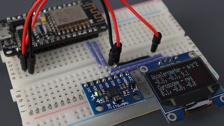
In this guide, you’ll learn how to use the MPU-6050 accelerometer and gyroscope module with the ESP8266 NodeMCU. The MPU-6050 is an Inertial Measurement Unit (IMU) featuring a 3-axis accelerometer and a 3-axis gyroscope. The accelerometer measures gravitational acceleration, while the gyroscope measures rotational velocity. Additionally, this module can measure temperature, making it ideal for determining the orientation of a moving object.
Parts Required
| Component Name | Buy Now |
| ESP8266 NodeMCU CP2102 | Amazon |
| MPU6050 3 Axis Accelerometer Gyroscope Module 6 DOF 6-axis | Amazon |
| 0.96 Inch OLED I2C IIC Display Module | Amazon |
Introducing the MPU-6050 Gyroscope Accelerometer Sensor
The MPU-6050 module includes a 3-axis accelerometer and a 3-axis gyroscope.
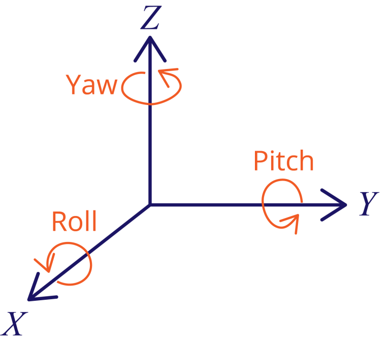
The gyroscope measures rotational velocity (in rad/s), which is the rate of change of angular position over time along the X, Y, and Z axes (roll, pitch, and yaw). This helps determine an object’s orientation.
The accelerometer measures acceleration, the rate of change of an object’s velocity. It can detect static forces like gravity (9.8 m/s²) and dynamic forces such as vibrations or movement. The MPU-6050 measures acceleration along the X, Y, and Z axes. For a stationary object, the Z-axis acceleration equals the gravitational force, and the X and Y axes should read zero.
Using accelerometer values, roll and pitch angles can be calculated through trigonometry, though yaw cannot be determined this way.
Combining data from both the accelerometer and gyroscope provides more accurate information about the sensor’s orientation.
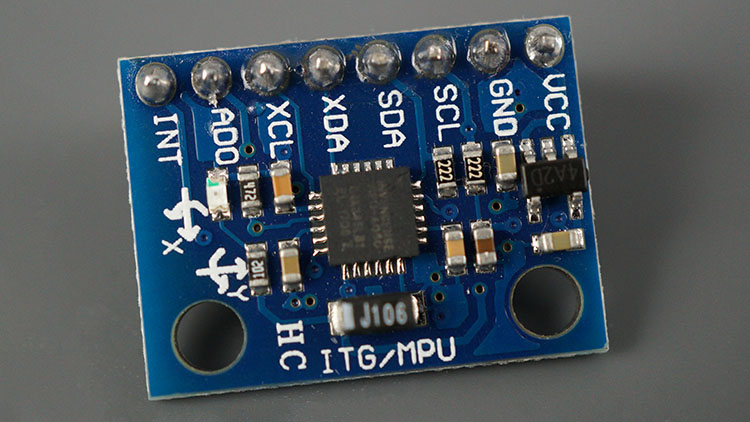
MPU-6050 Pinout
Here’s the pinout for the MPU-6050 sensor module.
| VCC | Power the sensor (3.3V or 5V) |
| GND | Common GND |
| SCL | SCL pin for I2C communication (GPIO 5) |
| SDA | SDA pin for I2C communication (GPIO 4) |
| XDA | Used to interface other I2C sensors with the MPU-6050 |
| XCL | Used to interface other I2C sensors with the MPU-6050 |
| AD0 | Use this pin to change the I2C address |
| INT | Interrupt pin – can be used to indicate that new measurement data is available |
Preparing Arduino IDE
Installing Libraries
There are several methods to obtain readings from the sensor. In this tutorial, we’ll use the Adafruit MPU6050 library. Additionally, you’ll need to install the Adafruit Unified Sensor library and the Adafruit Bus IO Library.
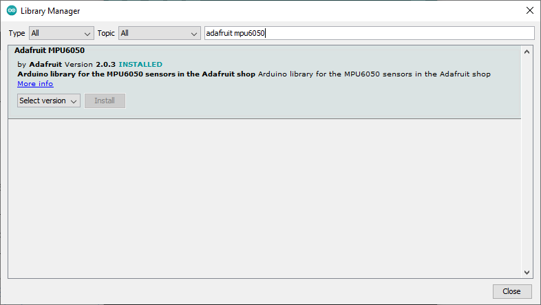
- Open the Arduino IDE and navigate to Sketch > Include Library > Manage Libraries. This will open the Library Manager.
- In the search box, type “adafruit mpu6050” and install the library.
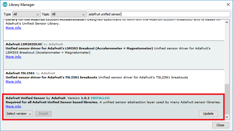
- Next, search for “Adafruit Unified Sensor”. Scroll down to locate the library and install it.
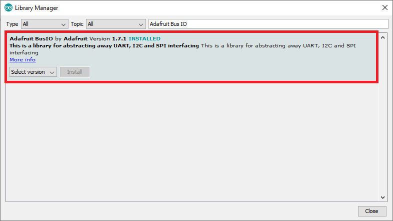
- Finally, search for “Adafruit Bus IO” and install it as well.
After installing all the required libraries, restart your Arduino IDE.
If you are using VS Code with PlatformIO, add the following lines to the platformio.ini file:
lib_deps = adafruit/Adafruit MPU6050 @ ^2.0.3
    adafruit/Adafruit Unified Sensor @ ^1.1.4
Getting MPU-6050 Sensor Readings: Accelerometer, Gyroscope, and Temperature
In this section, you’ll learn how to obtain sensor readings from the MPU-6050, including acceleration (x, y, z), angular velocity (x, y, z), and temperature.
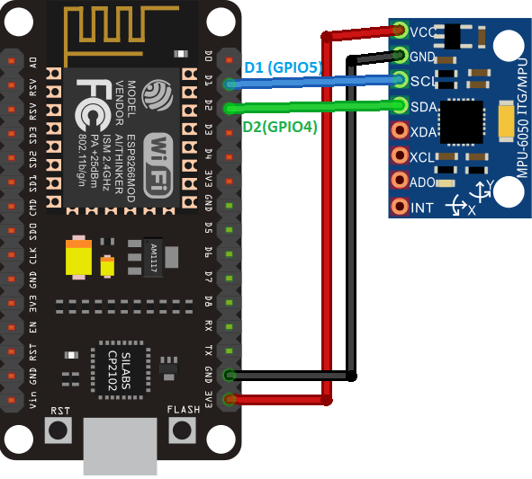
Schematic Diagram – ESP8266 NodeMCU with MPU-6050
To connect the ESP8266 to the MPU-6050 sensor, follow this schematic: connect the SCL pin to GPIO 5 and the SDA pin to GPIO 4.
Code – Obtaining MPU-6050 Sensor Readings
The Adafruit library includes several examples for this sensor. Here, we’ll use a basic example that displays sensor readings in the Serial Monitor.
- Go to File > Examples > Adafruit MPU6050 > basic_readings. This will load the following code.
This example retrieves the gyroscope’s angular velocity on the x, y, and z axes, the accelerometer’s readings on the x, y, and z axes, and the temperature.
#include <Adafruit_MPU6050.h>
#include <Adafruit_Sensor.h>
#include <Wire.h>

Adafruit_MPU6050 mpu;

void setup(void) {
  Serial.begin(115200);
  while (!Serial)
    delay(10); // will pause Zero, Leonardo, etc until serial console opens

  Serial.println("Adafruit MPU6050 test!");

  // Try to initialize!
  if (!mpu.begin()) {
    Serial.println("Failed to find MPU6050 chip");
    while (1) {
      delay(10);
    }
  }
  Serial.println("MPU6050 Found!");

  mpu.setAccelerometerRange(MPU6050_RANGE_8_G);
  Serial.print("Accelerometer range set to: ");
  switch (mpu.getAccelerometerRange()) {
  case MPU6050_RANGE_2_G:
    Serial.println("+-2G");
    break;
  case MPU6050_RANGE_4_G:
    Serial.println("+-4G");
    break;
  case MPU6050_RANGE_8_G:
    Serial.println("+-8G");
    break;
  case MPU6050_RANGE_16_G:
    Serial.println("+-16G");
    break;
  }
  mpu.setGyroRange(MPU6050_RANGE_500_DEG);
  Serial.print("Gyro range set to: ");
  switch (mpu.getGyroRange()) {
  case MPU6050_RANGE_250_DEG:
    Serial.println("+- 250 deg/s");
    break;
  case MPU6050_RANGE_500_DEG:
    Serial.println("+- 500 deg/s");
    break;
  case MPU6050_RANGE_1000_DEG:
    Serial.println("+- 1000 deg/s");
    break;
  case MPU6050_RANGE_2000_DEG:
    Serial.println("+- 2000 deg/s");
    break;
  }

  mpu.setFilterBandwidth(MPU6050_BAND_5_HZ);
  Serial.print("Filter bandwidth set to: ");
  switch (mpu.getFilterBandwidth()) {
  case MPU6050_BAND_260_HZ:
    Serial.println("260 Hz");
    break;
  case MPU6050_BAND_184_HZ:
    Serial.println("184 Hz");
    break;
  case MPU6050_BAND_94_HZ:
    Serial.println("94 Hz");
    break;
  case MPU6050_BAND_44_HZ:
    Serial.println("44 Hz");
    break;
  case MPU6050_BAND_21_HZ:
    Serial.println("21 Hz");
    break;
  case MPU6050_BAND_10_HZ:
    Serial.println("10 Hz");
    break;
  case MPU6050_BAND_5_HZ:
    Serial.println("5 Hz");
    break;
  }

  Serial.println("");
  delay(100);
}

void loop() {
  /* Get new sensor events with the readings */
  sensors_event_t a, g, temp;
  mpu.getEvent(&a, &g, &temp);

  /* Print out the values */
  Serial.print("Acceleration X: ");
  Serial.print(a.acceleration.x);
  Serial.print(", Y: ");
  Serial.print(a.acceleration.y);
  Serial.print(", Z: ");
  Serial.print(a.acceleration.z);
  Serial.println(" m/s^2");

  Serial.print("Rotation X: ");
  Serial.print(g.gyro.x);
  Serial.print(", Y: ");
  Serial.print(g.gyro.y);
  Serial.print(", Z: ");
  Serial.print(g.gyro.z);
  Serial.println(" rad/s");

  Serial.print("Temperature: ");
  Serial.print(temp.temperature);
  Serial.println(" degC");

  Serial.println("");
  delay(500);
}
Code Explanation
Start by including the necessary libraries for the MPU-6050 sensor: Adafruit_MPU6050 and Adafruit_Sensor.
#include <Adafruit_MPU6050.h>
#include <Adafruit_Sensor.h>
Create an Adafruit_MPU6050 object named mpu to manage the sensor.
Adafruit_MPU6050 mpu;
setup()
In the setup(), initialize the serial monitor with a baud rate of 115200.
Serial.begin(115200);
Initialize the MPU-6050 sensor.
if (!mpu.begin()) {
  Serial.println("Sensor init failed");
  while (1)
    yield();
}
Set the accelerometer measurement range:
mpu.setAccelerometerRange(MPU6050_RANGE_8_G);
Set the gyroscope measurement range:
mpu.setGyroRange(MPU6050_RANGE_500_DEG);
Set the filter bandwidth:
mpu.setFilterBandwidth(MPU6050_BAND_5_HZ);
loop()
In the loop(), get sensor readings and display them in the Serial Monitor.
First, retrieve new sensor events with the current readings.
sensors_event_t a, g, temp;
mpu.getEvent(&a, &g, &temp);
Print the acceleration readings:
Serial.print("Acceleration X: ");
Serial.print(a.acceleration.x);
Serial.print(", Y: ");
Serial.print(a.acceleration.y);
Serial.print(", Z: ");
Serial.print(a.acceleration.z);
Serial.println(" m/s^2");
Print the gyroscope readings:
Serial.print("Rotation X: ");
Serial.print(g.gyro.x);
Serial.print(", Y: ");
Serial.print(g.gyro.y);
Serial.print(", Z: ");
Serial.print(g.gyro.z);
Serial.println(" rad/s");
Print the temperature reading, measured in Celsius:
Serial.print("Temperature: ");
Serial.print(temp.temperature);
Serial.println(" degC");
Update sensor readings every 500 milliseconds.
delay(500);
Demonstration
Upload the code to your ESP8266 board. Go to Tools > Board and select your ESP8266 board. Then, go to Tools > Port and choose the correct port. Click the Upload button.
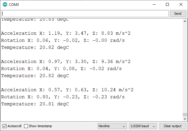
Open the Serial Monitor at a baud rate of 115200, then press the on-board RST button. The sensor measurements will appear, and you’ll see the values change as you move the sensor.
Sensor Calibration
Ideally, when the sensor is stationary, the gyroscope values should read zero on all axes, which is not the case here. When stationary, we get the following gyroscope values:
- x: 0.06 rad/s
- y: -0.02 rad/s
- z: 0.00 rad/s
In practical applications, you should account for these errors and correct the values in the code for more accurate readings.
The same applies to the accelerometer values. The z-axis acceleration should be close to the gravitational force (9.8 m/s²), and the x and y axes should be near zero. When stationary, we get these approximate values:
- x: 0.71 m/s²
- y: 0.28 m/s²
- z: 9.43 m/s²
Display MPU-6050 Readings on OLED Display
The Adafruit MPU6050 library includes an example that shows how to display gyroscope and accelerometer readings on an OLED display.
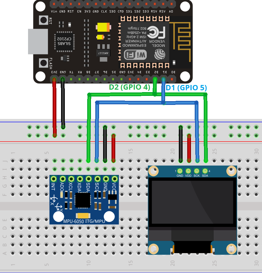
Schematic Diagram – ESP8266 NodeMCU with MPU-6050 and OLED Display
Connect the components as shown in the schematic diagram below. Since the OLED display and the MPU-6050 sensor use different I2C addresses, you can connect them to the same I2C bus (same pins on the ESP8266).
Code – Display MPU-6050 Sensor Readings on OLED Display
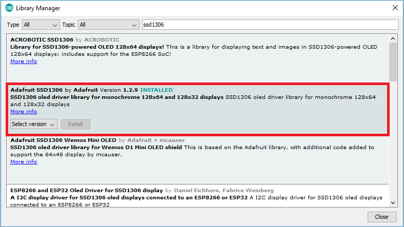
To run this example, ensure you have the Adafruit SSD1306 library installed. You can install it via the Arduino Library Manager.
- Go to Sketch > Include Library > Manage Libraries and search for “SSD1306”. Install the SSD1306 library from Adafruit.
- For this example, copy the following code or navigate to File > Examples > Adafruit MPU6050 > MPU6050_oled.
#include <Adafruit_MPU6050.h>
#include <Adafruit_SSD1306.h>
#include <Adafruit_Sensor.h>

Adafruit_MPU6050 mpu;
Adafruit_SSD1306 display = Adafruit_SSD1306(128, 64, &Wire);

void setup() {
  Serial.begin(115200);
  // while (!Serial);
  Serial.println("MPU6050 OLED demo");

  if (!mpu.begin()) {
    Serial.println("Sensor init failed");
    while (1)
      yield();
  }
  Serial.println("Found a MPU-6050 sensor");

  // SSD1306_SWITCHCAPVCC = generate display voltage from 3.3V internally
  if (!display.begin(SSD1306_SWITCHCAPVCC, 0x3C)) { // Address 0x3C for 128x64
    Serial.println(F("SSD1306 allocation failed"));
    for (;;)
      ; // Don't proceed, loop forever
  }
  display.display();
  delay(500); // Pause for 2 seconds
  display.setTextSize(1);
  display.setTextColor(WHITE);
  display.setRotation(0);
}

void loop() {
  sensors_event_t a, g, temp;
  mpu.getEvent(&a, &g, &temp);

  display.clearDisplay();
  display.setCursor(0, 0);

  Serial.print("Accelerometer ");
  Serial.print("X: ");
  Serial.print(a.acceleration.x, 1);
  Serial.print(" m/s^2, ");
  Serial.print("Y: ");
  Serial.print(a.acceleration.y, 1);
  Serial.print(" m/s^2, ");
  Serial.print("Z: ");
  Serial.print(a.acceleration.z, 1);
  Serial.println(" m/s^2");

  display.println("Accelerometer - m/s^2");
  display.print(a.acceleration.x, 1);
  display.print(", ");
  display.print(a.acceleration.y, 1);
  display.print(", ");
  display.print(a.acceleration.z, 1);
  display.println("");

  Serial.print("Gyroscope ");
  Serial.print("X: ");
  Serial.print(g.gyro.x, 1);
  Serial.print(" rps, ");
  Serial.print("Y: ");
  Serial.print(g.gyro.y, 1);
  Serial.print(" rps, ");
  Serial.print("Z: ");
  Serial.print(g.gyro.z, 1);
  Serial.println(" rps");

  display.println("Gyroscope - rps");
  display.print(g.gyro.x, 1);
  display.print(", ");
  display.print(g.gyro.y, 1);
  display.print(", ");
  display.print(g.gyro.z, 1);
  display.println("");

  display.display();
  delay(100);
}
Code Explanation
Start by including the necessary libraries for the MPU-6050 sensor and the OLED display.
#include <Adafruit_MPU6050.h>
#include <Adafruit_SSD1306.h>
#include <Adafruit_Sensor.h>
Create an Adafruit_MPU6050 object named mpu to manage the sensor.
Adafruit_MPU6050 mpu;
Create an Adafruit_SSD1306 object named display to handle the OLED display, specifying a resolution of 128×64 pixels.
Adafruit_SSD1306 display = Adafruit_SSD1306(128, 64, &Wire);
setup()
In the setup(), initialize the serial monitor with a baud rate of 115200.
Serial.begin(115200);
Initialize the MPU-6050 sensor.
if (!mpu.begin()) {
  Serial.println("Sensor init failed");
  while (1)
    yield();
}
Initialize the OLED display.
// SSD1306_SWITCHCAPVCC = generate display voltage from 3.3V internally
if (!display.begin(SSD1306_SWITCHCAPVCC, 0x3C)) { // Address 0x3C for 128x64
  Serial.println(F("SSD1306 allocation failed"));
  for (;;)
    ; // Don't proceed, loop forever
}
display.display();
Set the font size and color for the display.
display.setTextSize(1);
display.setTextColor(WHITE);
display.setRotation(0);
loop()
In the loop(), we’ll get sensor readings and display them on the OLED.
First, create events for each measurement: accelerometer, gyroscope, and temperature.
sensors_event_t a, g, temp;
Get new sensor readings.
mpu.getEvent(&a, &g, &temp);
Clear the display in each loop() to write new readings.
display.clearDisplay();
Set the display cursor to (0,0) – the upper left corner.
display.setCursor(0, 0);
Print the accelerometer readings on the Serial Monitor.
Serial.print("Accelerometer ");
Serial.print("X: ");
Serial.print(a.acceleration.x, 1);
Serial.print(" m/s^2, ");
Serial.print("Y: ");
Serial.print(a.acceleration.y, 1);
Serial.print(" m/s^2, ");
Serial.print("Z: ");
Serial.print(a.acceleration.z, 1);
Serial.println(" m/s^2");
Display the accelerometer readings on the OLED.
display.println("Accelerometer - m/s^2");
display.print(a.acceleration.x, 1);
display.print(", ");
display.print(a.acceleration.y, 1);
display.print(", ");
display.print(a.acceleration.z, 1);
display.println("");
Print the gyroscope readings on the Serial Monitor.
Serial.print("Gyroscope ");
Serial.print("X: ");
Serial.print(g.gyro.x, 1);
Serial.print(" rps, ");
Serial.print("Y: ");
Serial.print(g.gyro.y, 1);
Serial.print(" rps, ");
Serial.print("Z: ");
Serial.print(g.gyro.z, 1);
Serial.println(" rps");
Display the gyroscope readings on the OLED.
display.println("Gyroscope - rps");
display.print(g.gyro.x, 1);
display.print(", ");
display.print(g.gyro.y, 1);
display.print(", ");
display.print(g.gyro.z, 1);
display.println("");
Show the readings on the OLED.
display.display();
Update the readings every 100 milliseconds.
delay(100);
Demonstration
Upload the code to your ESP8266 board. Go to Tools > Board and select your ESP8266 board. Then, go to Tools > Port and choose the correct port. Click the Upload button.
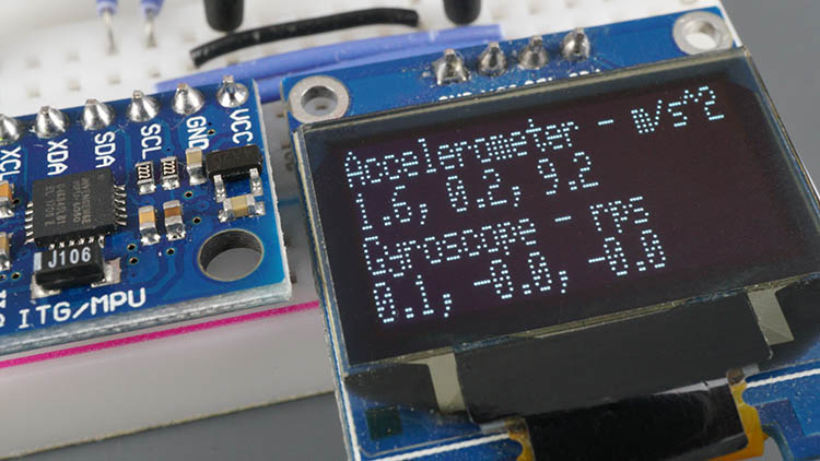
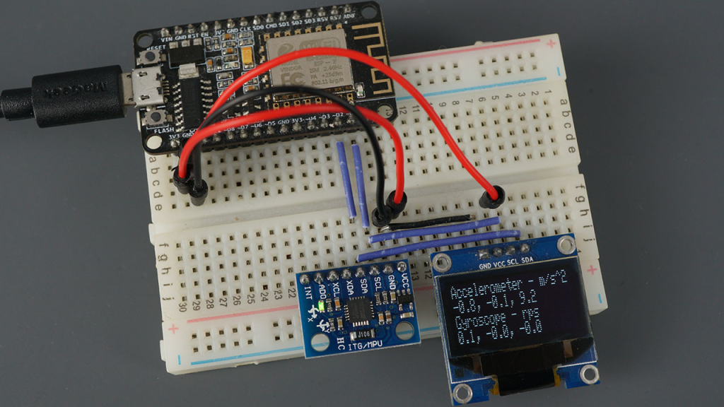
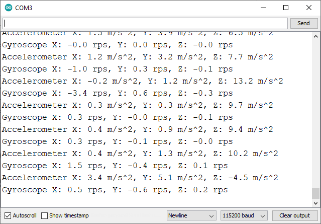
Open the Serial Monitor at a baud rate of 115200 and press the on-board RST button. The sensor measurements will be displayed on both the Serial Monitor and the OLED display. Move the sensor to see the values change.
Wrapping Up
The MPU-6050 is an accelerometer and gyroscope module that measures acceleration on the x, y, and z axes and angular velocity. It also measures temperature.
This sensor communicates via the I2C protocol, making wiring simple. Just connect the sensor to the ESP8266 default I2C pins.
In this tutorial, you’ve learned how to wire the sensor and obtain sensor readings. We hope you found this guide helpful. We also have guides for other popular sensors.
- Interfacing ESP32 with MPU-6050: Accelerometer, Gyroscope, and Temperature
- MPU6050 Accelerometer: Seamless Connection to Arduino Explained


