

Want to make your next Arduino project wireless for the cost of a cup of coffee? Consider using a 433MHz RF Transmitter and Receiver Module!
Available online for under two dollars, this is one of the most affordable data communication options out there. Plus, its compact size allows it to fit into nearly any project.
Hardware Overview
Let’s delve into the details of the 433MHz RF Transmitter and Receiver Modules.
The Transmitter
This small module acts as the transmitter. It features a SAW resonator tuned to 433.xx MHz, along with a switching transistor and some passive components. When the DATA input is high, the oscillator generates a continuous RF output carrier wave at 433.xx MHz. When the DATA input is low, the oscillator stops, resulting in an amplitude modulated wave. This method is called Amplitude Shift Keying, which we will explain in more detail soon.
The Receiver

This module functions as the receiver. Despite its complex appearance, it is as straightforward as the transmitter. It includes an RF tuned circuit and several operational amplifiers (OP Amps) that boost the received carrier wave. The amplified signal is then processed by a PLL (Phase Lock Loop), enabling the decoder to lock onto a stream of digital bits. This enhances the decoded output and improves noise immunity.
Parts Required
| Component Name | Buy Now |
| Arduino Uno REV3 | Amazon |
| 433M Transmitter + Receiver Kit High Frequency Super Regenerative Transceiver Module | Amazon |
ASK – Amplitude Shift Keying
As noted earlier, these modules use Amplitude Shift Keying (ASK) to transmit digital data over the radio. In ASK, the amplitude of the carrier wave (433 MHz in this case) is adjusted based on the incoming data signal.
ASK is similar to the Amplitude Modulation technique used in AM radio. With only two levels, it is sometimes called Binary Amplitude Shift Keying.
Think of it like an ON/OFF switch:
- For logic 1 – the carrier wave is transmitted.
- For logic 0 – no signal is transmitted.
Here is an illustration of Amplitude modulation:
The main advantage of Amplitude Shift Keying is its simplicity. The decoder circuitry is easy to design. Additionally, ASK requires less bandwidth compared to other modulation techniques like FSK (Frequency Shift Keying), making it cost-effective.
The drawback of ASK is its susceptibility to interference from other radio devices and ambient noise. However, transmitting data at a relatively slow rate can ensure reliable performance in most environments.
433MHz RF Transmitter & Receiver Pinout
Let’s take a look at the pinout of 433MHz RF Transmitter and Receiver Modules.
- DATA: pin accepts digital data to be transmitted.
- VCC: provides power to the transmitter. Any positive DC voltage between 3.5V and 12V can be used. It should be noted that the RF output is proportional to the supply voltage, so the higher the voltage, the greater the range.
- GND: is the ground pin.
- Antenna: is a pin that connects to the external antenna. To improve the range, you should solder a 17.3-centimeter-long solid wire to this pin. It is discussed in detail later.
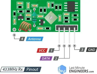
- VCC: provides power to the receiver. Unlike the transmitter, the receiver requires a 5V supply voltage.
- DATA: pins output the received digital data. Both pins are internally linked, so you can use either one for data out.
- GND: is the ground pin.
- Antenna: is a pin that connects to the external antenna. To improve the range, you should solder a 17.3-centimeter-long solid wire to this pin.
Wiring the 433MHz RF Transmitter and Receiver Modules to the Arduino
Now that we understand these modules, let’s put them into action!
To send data between two Arduino boards, you’ll need two Arduino boards, two breadboards, and some jumper wires.
Wiring for the Transmitter
Connecting the transmitter is straightforward since it has only three pins.
- Connect the VCC pin on the module to the Arduino’s 5V pin.
- Connect the GND pin to Ground.
- Connect the Data-in pin to digital pin #12 on the Arduino, as the library we use defaults to this pin.
Here is a table of the connections:
| Transmitter | Arduino |
| VCC | 5V |
| Data | 12 |
| GND | GND |
Refer to the image below for the wiring diagram.
Wiring for the Receiver
After wiring the transmitter, move on to the receiver. The receiver’s wiring is equally simple.
- Connect the VCC pin on the module to the Arduino’s 5V pin.
- Connect the GND pin to Ground.
- Connect one of the middle two data-out pins to the Arduino’s digital pin #11, as they are internally connected.
Here is a table of the connections:
| Receiver | Arduino |
| VCC | 5V |
| Data | 11 |
| GND | GND |
Refer to the image below for the wiring diagram.

RadioHead Library – The Versatile Tool for Wireless Modules
The 433MHz RF module, unlike advanced modules like the nRF24L01, lacks built-in error detection for data transmission. Thus, we need to implement CRC (Cyclic Redundancy Check) in our code.
This is where the popular RadioHead library proves invaluable. It handles CRC computations, ensuring more reliable communication. The RadioHead library is highly versatile, compatible with various RF modules, not just the 433MHz ones.
At the transmitter end, the RadioHead library packages the data into a data packet (known as a RadioHead Packet) with a CRC checksum and sends it to another Arduino with the necessary preamble and header. At the receiver end, the library notifies the receiving Arduino if the data is received correctly.
The RadioHead Packet
The RadioHead Packet is structured as follows: Each transmission begins with a 36-bit stream of alternating “1” and “0” pairs, called the “Training Preamble.” These bits help the receiver adjust its gain before receiving actual data. Next, a 12-bit “Start Symbol” is added, followed by the actual data (payload).
At the end of the packet, a Frame Check Sequence or CRC is included. The RadioHead library recalculates this CRC at the receiver end, and if it matches, the receiving device is notified. If the CRC check fails, the packet is discarded.
Here’s the structure of the RadioHead packet:
Download the Library
You can download the library from airspayce.com or by clicking the following link:
To install the library, open the Arduino IDE, go to Sketch > Include Library > Add .ZIP Library, and select the downloaded RadioHead file. For more details on installing a library, refer to the Installing an Arduino Library tutorial.
Arduino Example Code
In this experiment, we will send a short text message from the transmitter to the receiver to see if it can be decoded. This will help us understand how to use these modules and can serve as a basis for more advanced projects.
Transmitter Code
Here is the code for our transmitter:
// Include RadioHead Amplitude Shift Keying Library
#include <RH_ASK.h>
// Include dependant SPI Library
#include <SPI.h>

// Create Amplitude Shift Keying Object
RH_ASK rf_driver;

void setup()
{
    // Initialize ASK Object
    rf_driver.init();
}

void loop()
{
    const char *msg = "Hello World";
    rf_driver.send((uint8_t *)msg, strlen(msg));
    rf_driver.waitPacketSent();
    delay(1000);
}
Code Explanation:
This is a simple sketch that sends a message.
The sketch begins by including the RadioHead ASK library and the SPI library, which is required by the RadioHead library.
#include <RH_ASK.h>
#include <SPI.h>
Next, we create an ASK object to access the RadioHead ASK library functions.
// Create Amplitude Shift Keying Object
RH_ASK rf_driver;
In the setup function, we initialize the ASK object.
// Initialize ASK Object
rf_driver.init();
In the loop function, we prepare a message. This message is a text string stored in a character pointer called msg. Your message can be anything, but it should not exceed 27 characters for optimal performance. Our example message has 11 characters.
// Preparing a message
const char *msg = "Hello World";
We then send the message using the send() function, which takes two parameters: the data array and the number of bytes to send.
The send() function is followed by waitPacketSent(), which waits for the transmission to complete. The loop then pauses for a second to give the receiver time to process the message.
rf_driver.send((uint8_t *)msg, strlen(msg));
rf_driver.waitPacketSent();
delay(1000);
Receiver Code
Here is the code for our receiver. Connect the receiver circuit to your computer and upload the following sketch:
// Include RadioHead Amplitude Shift Keying Library
#include <RH_ASK.h>
// Include dependant SPI Library
#include <SPI.h>

// Create Amplitude Shift Keying Object
RH_ASK rf_driver;

void setup()
{
    // Initialize ASK Object
    rf_driver.init();
    // Setup Serial Monitor
    Serial.begin(9600);
}

void loop()
{
    // Set buffer to size of expected message
    uint8_t buf[11];
    uint8_t buflen = sizeof(buf);
    // Check if received packet is correct size
    if (rf_driver.recv(buf, &buflen))
    {

      // Message received with valid checksum
      Serial.print("Message Received: ");
      Serial.println((char*)buf);
    }
}
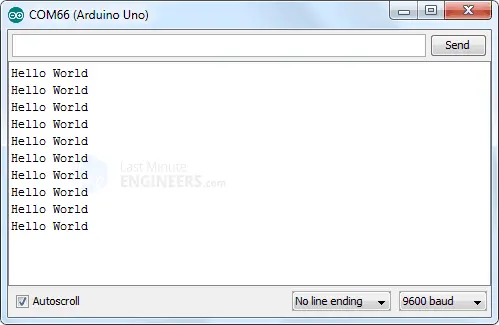
After uploading the sketch, open your serial monitor. If everything is set up correctly, you should see your message displayed.
Code Explanation:
The receiver code, like the transmitter code, starts by including the RadioHead and SPI libraries and creating an ASK object.
#include <RH_ASK.h>
#include <SPI.h>
RH_ASK rf_driver;
In the setup function, we initialize the ASK object and configure the serial monitor to display the received messages.
rf_driver.init();
Serial.begin(9600);
In the loop function, we create a buffer of the same size as the transmitted message. For our example, it is 11 characters. Adjust this to match the length of your message, including any spaces and punctuation.
uint8_t buf[11];
uint8_t buflen = sizeof(buf);
We then call the recv() function, which activates the receiver. When a valid message is received, it is copied into the buffer and the function returns true. If this happens, the received message is printed on the serial monitor.
if (rf_driver.recv(buf, &buflen))
{
  Serial.print("Message Received: ");
  Serial.println((char*)buf);
}
The loop then repeats, continuously checking for new messages.
Improving 433MHz RF module range with an antenna
The range of your 433MHz RF module can be greatly improved with the right antenna. Without an antenna, you’ll only get a range of about a meter. However, a properly designed antenna can extend this range to up to 50 meters.
Creating an effective antenna is simple. A single-core wire can be used to make a great antenna for both the transmitter and receiver.
The ideal antenna length matches the wavelength of the transmission frequency. However, using an antenna that’s half or a quarter of that length can also be effective.
The wavelength of a frequency is calculated as:
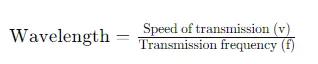
In air, the speed of transmission is the speed of light, which is approximately 299,792,458 m/s. For the 433 MHz band, the wavelength is:
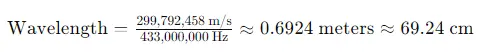
A 69.24 cm antenna is quite long and impractical, so a quarter-wave antenna, which is about 17.3 cm (6.8 inches), is often used.
It’s important to note that coiling the antenna to save space will greatly reduce its effectiveness. A straight antenna is always better for maximizing range!
- nRF24L01+ Wireless Module Interface with Arduino: Step-by-Step
- Arduino HC-05 Bluetooth Module Tutorial: Step-by-Step Guide
- Mastering Bluetooth Low Energy with ESP32 (BLE)


