
Enabling wireless communication between two or more Arduinos introduces a plethora of opportunities, including remote sensor data monitoring, robot control, home automation, and more.
When seeking an economical yet dependable two-way RF solution, the nRF24L01 arduino transceiver module from Nordic Semiconductor stands out.
With a cost of under two dollars online, the nRF24L01 module is exceptionally budget-friendly, rendering it one of the most cost-effective choices for data communication.
Hardware Overview
Wireless Communication Frequency
The nRF24L01+ module is crafted to operate within the globally recognized 2.4 GHz ISM (Industrial, Scientific, and Medical) frequency band, utilizing GFSK modulation for data transmission. This module’s data transfer rate is adjustable, allowing you to select from 250kbps, 1Mbps, or 2Mbps.
The 2.4 GHz band belongs to the ISM spectrum, an internationally reserved domain for unlicensed, low-power devices. Various gadgets, such as cordless phones, Bluetooth devices, Near Field Communication (NFC) devices, and wireless computer networks (WiFi), utilize ISM frequencies.
Power Management
Operating voltage for the module spans from 1.9V to 3.9V. It’s essential to note that supplying the module with 5V could potentially harm your nRF24L01 module.
Despite its operating range of 1.9V to 3.6V, the logic pins possess 5-volt tolerance, eliminating the need for a logic level translator.
The module’s output power can be adjusted to 0 dBm, -6 dBm, -12 dBm, or -18 dBm. At 0 dBm, the module consumes merely 12 mA during transmission, which is lower than the power consumption of a single LED.
Remarkably, the standby mode consumes only 26 µA, while the power-down mode is incredibly efficient at 900 nA. This outstanding energy efficiency makes it a preferred choice for applications demanding low power usage.
Serial Peripheral Interface (SPI)
Communication with the nRF24L01 arduino transpires through a 4-pin SPI (Serial Peripheral Interface), offering a maximum data rate of 10Mbps.
Through the SPI interface, you can configure all parameters, including frequency channel (with 125 selectable channels), output power (0 dBm, -6 dBm, -12 dBm, or -18 dBm), and data rate (250kbps, 1Mbps, or 2Mbps).
The SPI bus operates on the principle of a master-slave relationship. In most scenarios, the Arduino functions as the master, while the nRF24L01+ module serves as the slave.
Unlike the I2C bus, the SPI bus has a finite number of slaves it can support. Consequently, a single Arduino can accommodate up to two SPI slaves (two nRF24L01+ modules).
Technical Specifications
Here are the specifications:
| Frequency Range | 2.4 GHz ISM Band |
| Maximum Air Data Rate | 2 Mb/s |
| Modulation Format | GFSK |
| Max. Output Power | 0 dBm |
| Operating Supply Voltage | 1.9 V to 3.6 V |
| Max. Operating Current | 13.5mA |
| Min. Current(Standby Mode) | 26µA |
| Logic Inputs | 5V Tolerant |
| Communication Range | 800+ m (line of sight) |
For more information, please refer to the datasheet below.
Comparison: nRF24L01 Module vs. nRF24L01 PA/LNA Module
The nRF24L01+ chip serves as the core component in a range of modules, with two primary variants outlined below.
The first module integrates an onboard antenna, rendering it more compact in size. However, the smaller antenna footprint translates to a shorter transmission range. Outdoors, this module can facilitate communication up to a distance of 100 meters. It’s worth noting that this range might slightly diminish indoors due to obstacles like walls.
In contrast, the second module features an SMA connector accompanied by a duck antenna, but there’s more to it. It incorporates the RFX2401C range extender chip, which encompasses Power Amplifier (PA), Low-Noise Amplifier (LNA), and transmit-receive switching circuitry. As a result, this module achieves a substantially extended transmission range of up to 1000 meters.
Apart from this distinction, both modules are designed to be interchangeable without modifications. If you develop your project with one module, you can seamlessly switch to the other module without altering the system’s configuration.
Understanding PA and LNA:
PA, or Power Amplifier, solely magnifies the signal emitted by the nRF24L01 arduino chip during transmission. On the other hand, LNA, or Low-Noise Amplifier, is responsible for enhancing an exceedingly weak signal received from the antenna (typically in the microvolt range or around -100 dBm) to a more usable level (typically ranging from 0.5 to 1 V).
To facilitate a seamless connection between the low-noise amplifier (LNA) in the receive path and the power amplifier (PA) in the transmit path to the antenna, a duplexer is employed. This duplexer serves to isolate the two signals and prevent the relatively robust output from the power amplifier (PA) from overwhelming the delicate input of the low-noise amplifier (LNA). For additional insights, refer to this informative article on digikey.com.

How the nRF24L01+ Module Operates
RF Channel Frequency
The nRF24L01 module facilitates data transmission and reception via a specific frequency designated as a “channel.” To enable communication between two or more modules, they must share the same channel. This channel can encompass any frequency within the 2.4 GHz ISM band, specifically ranging from 2.400 to 2.525 GHz (2400 to 2525 MHz).
Each channel occupies a bandwidth of less than 1 MHz, offering 125 potential channels with a 1 MHz spacing.
This signifies that the nRF24L01+ can function across 125 distinct channels, enabling the creation of a network comprising 125 independently operational modems in a single location.
The RF channel frequency for a selected channel is calculated using the following formula:
Freq(Selected) = 2400 + CH(Selected)
For instance, opting for channel 108 for data transmission results in an RF channel frequency of 2508 MHz (2400 + 108).
nRF24L01+ Multiceiver Network
The nRF24L01+ module features a capability known as “Multiceiver,” which stands for “Multiple Transmitter Single Receiver.”
Within the framework of a multiceiver network, each RF channel is logically partitioned into six parallel data channels, referred to as “data pipes.” Essentially, these data pipes represent six distinct logical channels operating within a single physical RF channel. Each data pipe is assigned a unique address, known as a data pipe address. However, only one data pipe can receive a packet at any given moment.
This arrangement is illustrated below.
To better understand the concept of a multiceiver network, envision the primary receiver functioning as a central hub, simultaneously gathering data from six separate transmitter nodes. The hub receiver possesses the flexibility to switch between listening and transmitting as required.
Enhanced ShockBurst Protocol
The nRF24L01 arduino employs a packet structure known as “Enhanced ShockBurst,” encompassing five fields:
The original shockburst structure included Preamble, Address, Payload, and Cyclic Redundancy Check (CRC) fields. Enhanced ShockBurst introduced the Packet Control Field (PCF), augmenting functionality for more advanced communications.
This updated structure offers several advantages.
It supports variable length payloads, facilitated by a payload length specifier, accommodating payloads ranging from 1 to 32 bytes.
Each transmitted packet is assigned a packet ID, enabling the receiver to distinguish between new and retransmitted messages.
Each message includes a field prompting the receiver to issue an acknowledgment.
nRF24L01+ Automatic Packet Handling Scenarios
Let’s explore three scenarios to gain a better understanding of how interactions occur between two nRF24L01+ modules.
Transaction with Acknowledgment: This scenario exemplifies a positive interaction. The process begins with the transmitter initiating communication by sending a data packet to the receiver. After transmitting the packet, the transmitter awaits the acknowledgment (ACK), which typically takes around 130 microseconds (µs) to arrive. Upon successful reception, the receiver sends the ACK, indicating the packet’s safe delivery. With the receipt of the ACK, the transaction concludes.
Transaction with Lost Data Packet: In this negative scenario, packet retransmission becomes necessary due to packet loss during the initial transmission. Following packet transmission, the transmitter anticipates the arrival of an ACK. If the ACK is not received within the defined auto-retransmit-delay (ARD) period, the transmitter triggers a retransmission of the packet. Once the retransmitted packet reaches the receiver, the latter sends an ACK to confirm successful reception, bringing the transaction to an end.
Transaction with Lost Acknowledgment: Another unfavorable scenario involves retransmission due to the absence of an ACK. The transmitter, having not received the expected ACK, assumes the initial packet was lost, even if the receiver had indeed received it. Consequently, the transmitter retransmits the packet after an Auto-Retransmit-Delay timeout. Upon receiving a retransmitted packet with the same identification (ID), the receiver discards the duplicate and reissues the ACK. With the transmitter’s receipt of the ACK, the transaction reaches its conclusion.
It is important to note that throughout these scenarios, the nRF24L01+ chip orchestrates the entire packet handling process autonomously, requiring no intervention from the microcontroller. This feature streamlines communication and enhances the reliability of data exchange between the two modules.
nRF24L01 Pinout
Let’s explore the pin arrangements for both nRF24L01+ modules.
The GND pin functions as the ground connection. It bears a square marking, setting it apart from the other pins.
The VCC pin supplies power to the module, operating within a voltage range of 1.9 to 3.9 volts. You can link it to your Arduino’s 3.3V output. Nevertheless, exercise caution as connecting it to the 5V pin might potentially harm your nRF24L01+ module.
The CE (Chip Enable) pin maintains an active-high state. Enabling this pin determines whether the nRF24L01+ will transmit or receive data, contingent on its mode.
The CSN (Chip Select Not) pin adopts an active-low configuration and is typically held in a HIGH state. Reducing this pin’s signal to low triggers the nRF24L01+’s data reception on the SPI port and subsequent processing.
The SCK (Serial Clock) pin accepts clock pulses from the SPI bus master.
The MOSI (Master Out Slave In) pin functions as the SPI input for the nRF24L01+.
The MISO (Master In Slave Out) pin serves as the SPI output of the nRF24L01+.
The IRQ pin operates as an interrupt, signaling the master device when fresh data is ready for processing.
Wiring a nRF24L01+ module to an Arduino
Now that we have a comprehensive understanding of the nRF24L01+ module’s operation, we can proceed to establish a connection with our Arduino.
To start, link the VCC pin of the module to the Arduino’s 3.3V pin, and connect the GND pin to the ground. The CSN and CE pins can be attached to any available digital pin on the Arduino; in our case, we’ll use digital pins #8 and #9.
Next, let’s establish the connections for the SPI pins. It’s important to note that each type of Arduino board has its own specific set of SPI pins, which must be connected accordingly. For instance, on Arduino boards like the UNO/Nano V3.0, these SPI pins are designated as digital 13 (SCK), 12 (MISO), 11 (MOSI), and 10 (SS).
If you’re using a different model of Arduino board, it’s advisable to consult the official documentation to confirm the exact SPI pin locations before proceeding.
The following table provides a summary of the required pin connections:
| nRF24L01+ module | Arduino |
| GND | GND |
| VCC | 3.3V |
| CE | 9 |
| CSN | 8 |
| SCK | 13 |
| MOSI | 11 |
| MISO | 12 |
The accompanying images below illustrate the step-by-step process of connecting the nRF24L01 module to the Arduino.
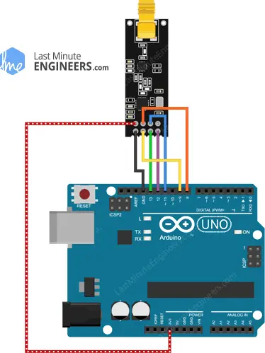
Keep in mind that you’ll need to replicate this circuit setup twice, creating two identical circuits. One circuit will function as the transmitter, and the other as the receiver. Both circuits share the same wiring configuration.
With all the connections in place, you are now prepared to proceed with your project!
Parts Required
| Component Name | Buy Now |
| Arduino Uno REV3 | Amazon |
| NRF24L01+PA+LNA Wireless Transceiver RF Transceiver Module 2.4G 1100m with Antenna | Amazon |
| NRF24L01+ Wireless Transceiver Module2.4G Wireless Transceiver Module | Amazon |
| Breadboard | Amazon |
| BOJACK 1000 Pcs 25 Values Resistor Kit 1 Ohm-1M Ohm with 5% 1/4W | Amazon |
Library Installation
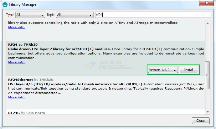
Numerous libraries are accessible for the nRF24L01 arduino, with one of the most prominent being the RF24 library. This library has maintained a significant presence over an extended period. It boasts user-friendliness for those new to the field, while also delivering a wealth of features for advanced users. We will employ this library in our illustrative instances.
To initiate the installation of the library, proceed to Sketch > Include Library > Manage Libraries… Await the Library Manager to finalize the download of the library index and update the roster of installed libraries.

To streamline your search, input ‘rf24‘. Identify the library authored by TmRh20. Select this entry and proceed to Install.
Arduino Transmitter Example Code
The provided examples illustrate the setup of a straightforward unidirectional connection between a transmitter and a receiver. The transmitter’s function is to send a conventional ‘Hello World’ message to the receiver, which subsequently displays it within the Serial Monitor interface.
Below is the code intended for our transmitter:
//Include Libraries
#include <SPI.h>
#include <nRF24L01.h>
#include <RF24.h>

//create an RF24 object
RF24 radio(9, 8);  // CE, CSN

//address through which two modules communicate.
const byte address[6] = "00001";

void setup()
{
  radio.begin();

  //set the address
  radio.openWritingPipe(address);

  //Set module as transmitter
  radio.stopListening();
}
void loop()
{
  //Send message to receiver
  const char text[] = "Hello World";
  radio.write(&text, sizeof(text));

  delay(1000);
}
Explanation of the Provided Code:
The code starts by including the necessary libraries for communication with the nRF24L01+ module. The SPI.h library manages SPI communication, while the nRF24L01.h and RF24.h libraries provide functions to control the module.
//Include Libraries
#include <SPI.h>
#include <nRF24L01.h>
#include <RF24.h>
An instance of the RF24 class named radio is created. The constructor takes two pin numbers (9 and 8) as arguments, corresponding to the Chip Enable (CE) and Chip Select Not (CSN) pins on the Arduino board.
RF24 radio(9, 8); // CE, CSN
A byte array named address is defined to store the pipe address that both the transmitter and receiver will use for communication.
const byte address[6] = "00001";
radio.begin();: Initializes communication with the nRF24L01 module.radio.openWritingPipe(address);: Sets the communication pipe address to be used by the transmitter.radio.stopListening();: Configures the module as a transmitter by disabling the listening mode.
void setup()
{
  radio.begin();
  radio.openWritingPipe(address);
  radio.stopListening();
}
- An array of characters named
textis created to store the message “Hello World.” radio.write(&text, sizeof(text));: Sends the message to the receiver using thewrite()function. The message and its size are provided as arguments.
void loop()
{
  const char text[] = "Hello World";
  radio.write(&text, sizeof(text));
  delay(1000);
}
Note: The maximum packet size that the nRF24L01+ can handle is 32 bytes. The write() function returns a boolean value (true or false) indicating whether the data was successfully received by the receiver. The function halts the program until an acknowledgment is received or all retransmission attempts are exhausted.
In summary, this code sets up an nRF24L01+ module as a transmitter using Arduino. It establishes a wireless link to send a “Hello World” message to a receiver. The transmitter initializes communication, sets the pipe address, and sends the message repeatedly with a delay of 1 second. The success of data transmission is indicated by the return value of the write() function.
Arduino Example Code – For Receiver
This is the code we’ll use for our receiver.
//Include Libraries
#include <SPI.h>
#include <nRF24L01.h>
#include <RF24.h>

//create an RF24 object
RF24 radio(9, 8);  // CE, CSN

//address through which two modules communicate.
const byte address[6] = "00001";

void setup()
{
  while (!Serial);
    Serial.begin(9600);

  radio.begin();

  //set the address
  radio.openReadingPipe(0, address);

  //Set module as receiver
  radio.startListening();
}

void loop()
{
  //Read the data if available in buffer
  if (radio.available())
  {
    char text[32] = {0};
    radio.read(&text, sizeof(text));
    Serial.println(text);
  }
}
Explanation of the Code
With a few minor adjustments, this code closely resembles the transmitter’s code.
In the setup function’s beginning, serial communication is initialized. Using the openReadingPipe() function, the same pipe address as the transmitter is established. This synchronization facilitates bidirectional communication between the transmitter and receiver.
The first parameter of the openReadingPipe() function designates the reading pipe. As up to six pipes can be concurrently opened for reading, the valid range is 0 to 5. In this case, we set pipe 0 for reading. The second parameter is the 40-bit address associated with the pipe.
  //set the address
  radio.openReadingPipe(0, address);
Afterward, the module is configured as a receiver, initiating the reception of data. The startListening() function serves this purpose.
//Set module as receiver
  radio.startListening();
Within the loop section, the available() method determines whether data is available for reading. It returns TRUE if data exists; otherwise, it returns FALSE.
if (radio.available())
  {
    char text[32] = {0};
    radio.read(&text, sizeof(text));
    Serial.println(text);
  }
When data is present, a character array of 32 elements, initialized with zeros, is created to store the data. The read(&text, sizeof(text)) method extracts data from the buffer and saves it in the character array.
Ultimately, the received message is displayed on the serial monitor. If all is well, the serial monitor output should resemble the following:
Received message: Hello World
This code explanation details how the receiver module interacts with the nrf24l01 transmitter and receiver. It demonstrates the reception process, including initializing communication, configuring the receiver, checking for available data, and displaying the received message in the serial monitor.
Enhancing nRF24L01+ Module Range
Communication range stands as a pivotal aspect in wireless systems, often influencing the choice of an RF solution. Let’s delve into strategies to augment the reach of our nRF24L01+ module.
Mitigate Power Supply Noise
Radio frequency (RF) signal generation hinges on a stable power supply, susceptible to disruption by power supply noise. Uncontrolled noise can substantially curtail achievable range.
Unless sourced from an isolated battery, power output frequently carries noise. A recommended approach to thwart this intrusion involves placing a 10 µf filter capacitor directly across the nRF24L01+ module’s power supply line.
An uncomplicated route to diminish power supply noise is utilizing an inexpensive adapter tailored for the nRF24L01 arduino.
This adapter offers an 8-pin female connector for seamless nRF24L01+ module integration. It accommodates both module variants: one with an integrated antenna and another with an external antenna (PA/LNA).
Additionally, it furnishes a 2-pin power input connector and a 6-pin male connector catering to SPI and interrupt connections.
Given its integrated 3.3V voltage regulator and filter capacitors, this adapter can be powered safely using a 5V power supply.
Alter Channel Frequency
External surroundings also serve as potential noise sources for RF circuits, particularly if neighboring networks occupy the same channel.
Optimal noise mitigation involves leveraging the highest 25 channels available in your nRF24L01+ setup. Steering clear of frequencies predominantly used by WiFi aids in evading interference from such signals.
Opt for Lower Data Rate
The nRF24L01+ boasts remarkable receiver sensitivity at 250Kbps, with a value of -94dBm. This sensitivity diminishes to -82dBm when the data rate ramps up to 2MBps. This implies that the receiver’s sensitivity at 250kbps is approximately tenfold greater than at 2Mbps, rendering it adept at decoding signals ten times weaker.
Reducing the data rate can substantially amplify achievable range. Moreover, a speed of 250kbps generally suffices for the majority of projects.
Receiver Sensitivity Unveiled
Receiver sensitivity represents the minimum power level at which an RF signal can be detected. A higher absolute value of the negative number corresponds to greater receiver sensitivity. For instance, a receiver sensitivity of −94dBm outperforms a sensitivity of −82dBm by a margin of 12dB.
Harness Higher Output Power
Optimal setting of the maximum output power can also contribute to extended communication range. The nRF24L01 arduino facilitates several output power levels, encompassing 0dBm, -6dBm, -12dBm, and -18dBm. While a 0dBm output power bolsters signal strength, it does consume more power.
The aforementioned adapter streamlines nRF24L01+ module integration. Its 8-pin female connector is primed for both module versions, accompanied by an integrated or external antenna (PA/LNA).
Further, it incorporates a 2-pin power input connector and a 6-pin male connector for SPI and interrupt connections.
Thanks to its embedded 3.3V voltage regulator and filter capacitors, the adapter can be seamlessly powered via a 5V power supply.
Related article
- Mastering AT Commands for HC-05 Configuration
- Master-Slave Arduino Wireless Communication with HC-05 Modules
- Arduino HC-05 Bluetooth Module Tutorial: Step-by-Step Guide
- 433MHz RF Tx-Rx Modules: Arduino Interface and Operation Explained
- Arduino and GPS: How to Interface NEO-6M Module
- How to Interface XBee S2 (ZigBee) with Arduino UNO for Beginners


