

Enhance your next Arduino project with the NEO-6M GPS module, capable of tracking 22 satellites to pinpoint locations worldwide. It’s an excellent starting point for anyone interested in GPS technology.
These modules are low power, making them ideal for battery-powered devices. They are also affordable, easy to integrate, and widely popular among hobbyists.
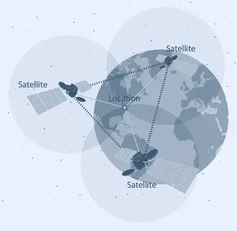
The GPS system comprises over 30 navigation satellites orbiting the Earth. These satellites continuously broadcast their position and time data to Earth via radio signals.
A GPS receiver picks up these signals and, by calculating its distance from at least three satellites, determines your precise location.
This technique is known as trilateration.
Hardware Overview
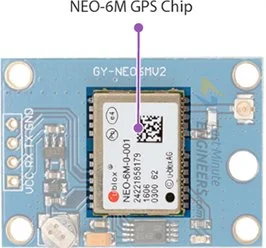
NEO-6M GPS Chip
At the core of the module is the NEO-6M GPS chip from U-blox. This compact chip, smaller than a postage stamp, boasts an impressive array of features.
It can track up to 22 satellites across 50 channels and offers industry-leading tracking sensitivity of -161 dB while consuming only 45 mA of current.
This GPS module stands out with its capability to perform 5 location updates per second and achieve 2.5m horizontal position accuracy. The U-blox 6 positioning engine also features a Time-To-First-Fix (TTFF) of under 1 second.
One notable feature of the chip is Power Save Mode (PSM), which reduces system power consumption by selectively activating and deactivating certain receiver components. This feature can lower the module’s power usage to just 11mA, making it ideal for power-sensitive applications like GPS wristwatches.
The NEO-6M GPS chip’s essential data pins are accessible via 0.1″ pitch headers, enabling communication with a microcontroller over UART. The module supports baud rates ranging from 4800bps to 230400bps, with a default of 9600bps.
Specifications:
| Receiver Type | 50 channels, GPS L1(1575.42Mhz) |
| Horizontal Position Accuracy | 2.5m |
| Navigation Update Rate | 1HZ (5Hz maximum) |
| Capture Time | Cool start: 27sHot start: 1s |
| Navigation Sensitivity | -161dBm |
| Communication Protocol | NMEA, UBX Binary, RTCM |
| Serial Baud Rate | 4800-230400 (default 9600) |
| Operating Temperature | -40°C ~ 85°C |
| Operating Voltage | 2.7V ~ 3.6V |
| Operating Current | 45mA |
| TXD/RXD Impedance | 510Ω |
For more information, please refer to the datasheet below.
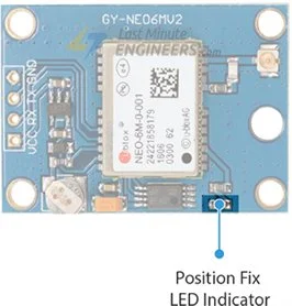
Position Fix LED Indicator
The NEO-6M GPS module includes an LED that shows the status of the ‘Position Fix.’ The blinking pattern of the LED indicates different states:
- No blinking: Searching for satellites.
- Blinks every 1 second: Position Fix acquired (sufficient satellites are detected).
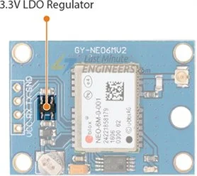
3.3V LDO Regulator
The NEO-6M chip operates on a voltage range of 2.7 to 3.6V. Fortunately, this module includes MICREL’s MIC5205 Ultra-Low Dropout 3V3 regulator.
The logic pins are 5-volt tolerant, allowing easy connection to an Arduino or any 5V logic microcontroller without needing a logic level converter.
Battery & EEPROM
The module features an HK24C32 Two Wire Serial EEPROM with 4KB capacity, connected to the NEO-6M chip via I2C.
It also includes a rechargeable button battery that functions as a super-capacitor.
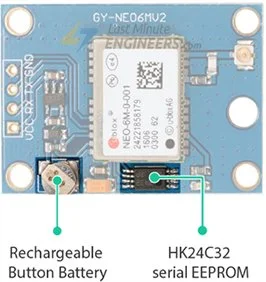
Together, the EEPROM and battery support the BBR (Battery Backed RAM), which stores clock data, recent position data (GNSS orbit data), and module configuration. However, it is not meant for permanent data storage.
The battery automatically charges when the module is powered and retains data for two weeks without power.
The battery helps retain clock and last position data, significantly reducing the Time-To-First-Fix (TTFF) to 1 second, enabling faster position locks. Without the battery, the GPS always cold-starts and takes longer for the initial lock.
Antenna
The module includes a patch antenna with -161 dBm sensitivity for receiving signals from GPS satellites.
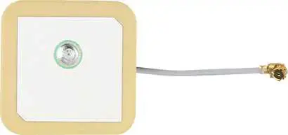
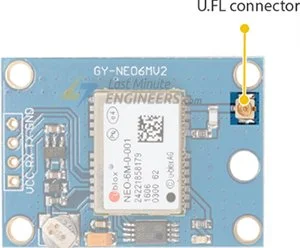
This antenna can be connected to the small U.FL connector on the module.
The patch antenna is suitable for most projects, but for enhanced sensitivity and accuracy, you can connect a 3V active GPS antenna.
NEO-6M GPS Module Pinout
The NEO-6M GPS module features four pins for connection:
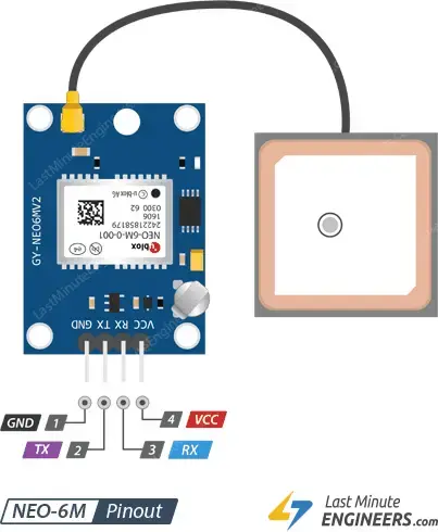
- GND: This ground pin should be connected to the Arduino’s GND pin.
- TxD (Transmitter): Used for serial communication.
- RxD (Receiver): Used for serial communication.
- VCC: Powers the module, which can be connected directly to the Arduino’s 5V pin.
Connecting the NEO-6M GPS Module to an Arduino
With an understanding of the module, we can proceed to connect it to an Arduino.
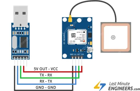
- Attach the patch antenna to the U.FL connector, threading the U.FL cable through one of the mounting holes for strain relief.
- Solder the header pins to the module if they are not already soldered.
- Connect the VCC pin to the Arduino’s 5V pin and the GND pin to the Arduino’s ground.
- Connect the module’s Tx pin to Arduino digital pin #2 and the Rx pin to digital pin #3.
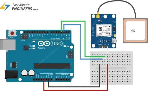
With these connections, your setup is complete and ready for use!
Parts Required
| Component Name | Buy Now |
| Arduino Uno REV3 | Amazon |
| GY-NEO6MV2 NEO-6M GPS Flight Controller Module 3V-5V | Amazon |
Arduino Code – Reading GPS Data
The NEO-6M GPS receiver starts sending data immediately after being powered on. The following sketch reads this data and outputs it to the serial monitor.
#include <SoftwareSerial.h>

// Choose two Arduino pins to use for software serial
int RXPin = 2;
int TXPin = 3;

//Default baud of NEO-6M is 9600
int GPSBaud = 9600;

// Create a software serial port called "gpsSerial"
SoftwareSerial gpsSerial(RXPin, TXPin);

void setup()
{
  // Start the Arduino hardware serial port at 9600 baud
  Serial.begin(9600);

  // Start the software serial port at the GPS's default baud
  gpsSerial.begin(GPSBaud);
}

void loop()
{
  // Displays information when new sentence is available.
  while (gpsSerial.available() > 0)
    Serial.write(gpsSerial.read());
}
Upload the program and open the Serial Monitor in the Arduino IDE, ensuring the baud rate is set to 9600. You should see text output similar to the following:
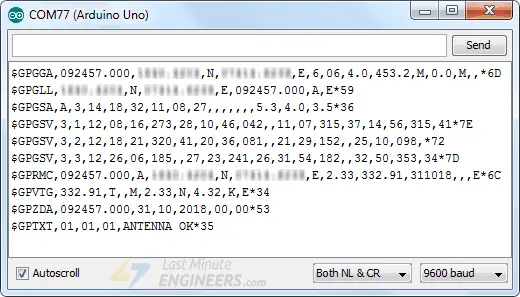
NMEA Sentences
The data appearing on the serial monitor consists of NMEA sentences.
NMEA stands for National Marine Electronics Association, which defines a standard message format for most GPS receivers.
NMEA data is structured in rows called sentences, with each sentence containing comma-separated data fields for easy parsing by computers and microcontrollers.
These NMEA sentences are transmitted at an interval known as the update rate.
By default, the NEO-6M GPS module updates this information once per second (1Hz). However, it can be configured to update up to five times per second (5Hz).
Parsing NMEA Sentences
It is common for microcontrollers to read NMEA sentences and parse them in a user-friendly form. Parsing is simply extracting chunks of data from the NMEA sentence.
There are many sentences in the NMEA standard. The most common are:
- $GPRMC provides time, date, latitude, longitude, altitude, and estimated velocity.
- $GPGGA sentence provides essential fix data which provides the 3D location and accuracy data.
$GPRMC NMEA sentence
To understand the NMEA message structure, let’s first examine the popular $GPRMC message.
$GPRMC, 123519, A, 4807.038, N, 01131.000, E,022.4, 084.4, 230394, 003.1, W*6A
| $ | Every NMEA sentence starts with $ character. |
| GPRMC | Global Positioning Recommended Minimum Coordinates |
| 123519 | Current time in UTC – 12:35:19 |
| A | Status A=active or V=Void. |
| 4807.038,N | Latitude 48 deg 07.038′ N |
| 01131.000,E | Longitude 11 deg 31.000′ E |
| 022.4 | Speed over the ground in knots |
| 084.4 | Track angle in degrees True |
| 220318 | Current Date – 22rd of March 2018 |
| 003.1,W | Magnetic Variation |
| *6A | The checksum data, always begins with * |
$GPGGA NMEA sentence
Let’s take an example of $GPGGA NMEA sentence.
$GPGGA, 123519, 4807.038, N, 01131.000, E, 1, 08, 0.9, 545.4, M, 46.9, M, , *47
| $ | Starting of NMEA sentence. |
| GPGGA | Global Positioning System Fix Data |
| 123519 | Current time in UTC – 12:35:19 |
| 4807.038,N | Latitude 48 deg 07.038′ N |
| 01131.000,E | Longitude 11 deg 31.000′ E |
| 1 | GPS fix |
| 08 | Number of satellites being tracked |
| 0.9 | Horizontal dilution of position |
| 545.4,M | Altitude in Meters (above mean sea level) |
| 46.9,M | Height of geoid (mean sea level) |
| (empty field) | Time in seconds since last DGPS update |
| (empty field) | DGPS station ID number |
| *47 | The checksum data, always begins with * |
$GPRMC and $GPGGA are basic GPS NMEA sentences. There are many alternative and companion NMEA sentences that provide similar or additional information. For more information on other NMEA sentences, visit gpsinformation.org
Library Installation
While NMEA sentences are easy to parse due to their comma-delimited format, libraries can simplify the process further. One popular library is TinyGPS++, which we will use in our examples.
TinyGPS++ provides straightforward methods for extracting data such as position, date, time, altitude, speed, and course from GPS devices.
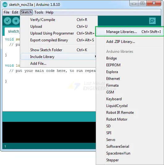
Since this library isn’t included with the Arduino IDE, you’ll need to install it manually.
To install the library, navigate to Sketch > Include Library > Manage Libraries…. Wait for the Library Manager to download the library index and update the list of available libraries.
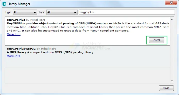
Filter your search by typing ‘tinygpsplus’. Click on the TinyGPS++ entry and select Install.
Arduino Code – TinyGPS++ Library
After installing the library, you can use the following sketch in the Arduino IDE.
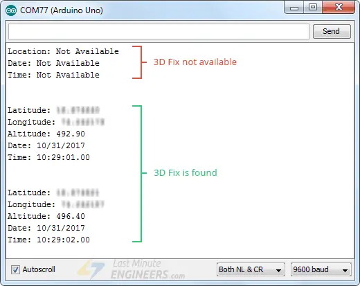
This test sketch prints location information (latitude, longitude, and altitude) and UTC (date and time) to the serial monitor. Try running the sketch before we explain it in detail.
#include <TinyGPS++.h>
#include <SoftwareSerial.h>

// Choose two Arduino pins to use for software serial
int RXPin = 2;
int TXPin = 3;

int GPSBaud = 9600;

// Create a TinyGPS++ object
TinyGPSPlus gps;

// Create a software serial port called "gpsSerial"
SoftwareSerial gpsSerial(RXPin, TXPin);

void setup()
{
  // Start the Arduino hardware serial port at 9600 baud
  Serial.begin(9600);

  // Start the software serial port at the GPS's default baud
  gpsSerial.begin(GPSBaud);
}

void loop()
{
  // This sketch displays information every time a new sentence is correctly encoded.
  while (gpsSerial.available() > 0)
    if (gps.encode(gpsSerial.read()))
      displayInfo();

  // If 5000 milliseconds pass and there are no characters coming in
  // over the software serial port, show a "No GPS detected" error
  if (millis() > 5000 && gps.charsProcessed() < 10)
  {
    Serial.println("No GPS detected");
    while(true);
  }
}

void displayInfo()
{
  if (gps.location.isValid())
  {
    Serial.print("Latitude: ");
    Serial.println(gps.location.lat(), 6);
    Serial.print("Longitude: ");
    Serial.println(gps.location.lng(), 6);
    Serial.print("Altitude: ");
    Serial.println(gps.altitude.meters());
  }
  else
  {
    Serial.println("Location: Not Available");
  }

  Serial.print("Date: ");
  if (gps.date.isValid())
  {
    Serial.print(gps.date.month());
    Serial.print("/");
    Serial.print(gps.date.day());
    Serial.print("/");
    Serial.println(gps.date.year());
  }
  else
  {
    Serial.println("Not Available");
  }

  Serial.print("Time: ");
  if (gps.time.isValid())
  {
    if (gps.time.hour() < 10) Serial.print(F("0"));
    Serial.print(gps.time.hour());
    Serial.print(":");
    if (gps.time.minute() < 10) Serial.print(F("0"));
    Serial.print(gps.time.minute());
    Serial.print(":");
    if (gps.time.second() < 10) Serial.print(F("0"));
    Serial.print(gps.time.second());
    Serial.print(".");
    if (gps.time.centisecond() < 10) Serial.print(F("0"));
    Serial.println(gps.time.centisecond());
  }
  else
  {
    Serial.println("Not Available");
  }

  Serial.println();
  Serial.println();
  delay(1000);
}
The serial monitor output should look like this.
Code Explanation:
The sketch begins by including the newly installed TinyGPS++ library and the SoftwareSerial library. Then those arduino pins are declared to which the NEO-6M GPS module is connected and a variable that stores the default GPS baud rate.
Creating a TinyGPSPlus object will help access special functions related to the library. After this we create a software serial port called gpsSerial through which we will talk to the module.
#include <TinyGPS++.h>
#include <SoftwareSerial.h>

int RXPin = 2;
int TXPin = 3;
int GPSBaud = 9600;

TinyGPSPlus gps;
SoftwareSerial gpsSerial(RXPin, TXPin);
In the setup function, we initiate the serial communication with the PC as well as the GPS module.
void setup()
{
  Serial.begin(9600);
  gpsSerial.begin(GPSBaud);
}
In the loop function, the displayInfo() custom function is called which prints location information (latitude, longitude and altitude) and UTC (date and time) to the serial monitor, each time a new NMEA sentence is encoded correctly.
If 5000 milliseconds elapse and no characters arrive at the software serial port, a ‘No GPS detected’ error message is printed.
void loop()
{
  while (gpsSerial.available() > 0)
    if (gps.encode(gpsSerial.read()))
      displayInfo();

  if (millis() > 5000 && gps.charsProcessed() < 10)
  {
    Serial.println(F("No GPS detected"));
    while(true);
  }
}
Other Useful Functions In TinyGPS++ Library
There are many useful functions you can use with a TinyGPS++ object. Some of them are listed below:
gps.speed.value()function returns the current ground speed in 100ths of a knot.
gps.course.value()function returns the current ground course in 100ths of a degree.
gps.satellites.value()function returns the number of visible and participating satellites.
gps.hdop.value()function returns the horizontal loss of precision.
gps.age()function tells how old an object’s data is. It returns the number of milliseconds since its last update. If the value is 1500 or more, it may indicate a ‘lost fix’.
- If you want to extract data from another NMEA sentence. You can use the library’s custom extraction functionality by telling TinyGPS++ the name of the sentence and the field number you are interested in. If you want to know the magnetic variation, for example, you can call:
TinyGPSCustom magneticVariation(gps, "GPRMC", 10);You can then query it like this:magneticVariation.value()
U-center software
The U-center from u-blox is a powerful tool for the evaluation, performance analysis and configuration of u-blox GPS receivers, including the NEO-6M. It is a free tool but it can be used only on Windows platform.
It can display realtime structured and graphical data visualizations from any GPS receiver such as:
- Satellite Summary View
- Navigation Summary View
- Compass, speedometer, clock, altimeter
- Chart view of any two parameters of choice
- Data Recording and Playback Functionality
This software can be downloaded from u-blox website.
Connecting NEO-6M to U-center
To use the U-Center software, you need to connect your NEO-6M to your PC using a USB to TTL converter.
The image below shows the NEO-6M connected to the PC with the PL2303 USB to TTL converter.
Using U-center
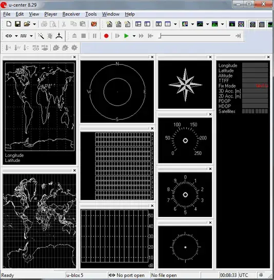
After a successful installation, U-Center can be started from the Start Menu (All Programs -> u-blox-> u-center -> u-center), it will start up as shown below.
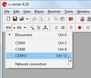
Locate the Communications toolbar and click the arrow next to the icon. This will show a list of all available COM ports. Select the corresponding COM port where the receiver is connected.
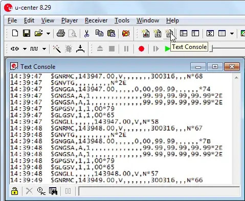
The Text Console button will show you the raw NMEA sentences. This is handy for quickly inspecting visible ASCII coming from the module over USB.
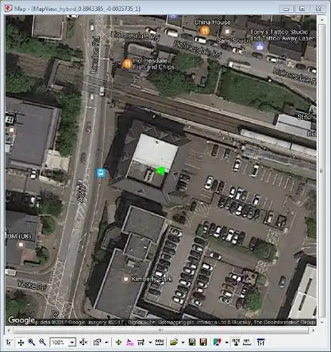
u-center can display position on Google Maps (offline/online) as well.
For more information about U-center software, please refer this user guide.
- Arduino HC-05 Bluetooth Module Tutorial: Step-by-Step Guide
- Mastering Bluetooth Low Energy with ESP32 (BLE)
- nRF24L01+ Wireless Module Interface with Arduino: Step-by-Step
- 433MHz RF Tx-Rx Modules: Arduino Interface and Operation Explained


