

If you need to listen to what’s happening in your home miles away or activate your garden’s sprinkler system with a simple call, the A6 GSM/GPRS module is an excellent starting point for your IoT projects.
The A6 GSM/GPRS module is a compact GSM modem that can be integrated into various IoT applications. With this module, you can send SMS text messages, make or receive phone calls, connect to the internet via GPRS, use TCP/IP, and more. Additionally, it supports quad-band GSM/GPRS networks, making it functional almost anywhere globally.
Hardware Overview of the A6 GSM/GPRS Module
The A6 GSM/GPRS module features the A6 GSM cellular chip from Ai-Thinker, known for their ESP8266 WiFi modules. It communicates with a microcontroller via UART and supports baud rates from 1200bps to 115200bps with auto-baud detection. All necessary data pins are accessible through 0.1″ pitch headers.
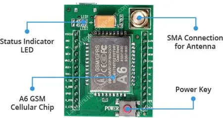
An external antenna is required for voice, data communications, and some SIM commands. The module typically includes a small duck antenna with 2 dBi gain and 50Ω impedance, providing excellent coverage even indoors.
A power button allows manual control to turn the module on or off, though this can also be done programmatically. The module’s status is indicated by an LED located on the top right.
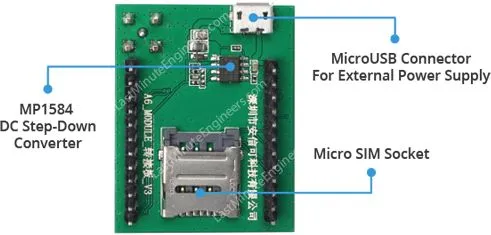
While the module can operate on 5V, the chip’s operating voltage ranges from 3.3V to 4.2V. To ensure a stable supply voltage of 4.1V, the module includes a high-frequency step-down switching regulator (MP1584 from Monolithic Power Systems), capable of handling load currents up to 3A.
The module can also be powered via a micro USB connector, allowing you to use a standard cell phone charger (rated 5V 2A) to power it.
A SIM socket on the back supports any activated 2G micro SIM card. To use it, push the top part of the assembly towards the micro USB connector, lift it, place the SIM card with the notch facing away from the micro USB connector, fold the arm back, and push it gently towards the “LOCK” position.
Despite its small size, the A6 GSM cellular chip offers numerous features:
- Supports quad-band: GSM850, EGSM900, DCS1800, and PCS1900
- Connects to any global GSM network with a 2G SIM
- Enables voice calls using an external 8Ω speaker and electret microphone
- Allows connection of a 4-pole TRRS mic and headset
- Facilitates voice calls and SMS messaging
- Class 10 GPRS with download speeds of 85.6Kbps and upload speeds of 42.8Kbps
- Consumes less than 3mA in standby mode
- 2.8V UART port level, compatible with Arduino and Raspberry Pi
- Transmit power:
- Class 4 (2W) for GSM850/EGSM900
- Class 1 (1W) for DCS1800/PCS1900
- Supports a serial-based AT Command Set
- Accepts micro SIM cards
A6 GSM Module Pinout
The A6 GSM module has a total of 24 pins for interfacing with external devices. The connections are as follows:

- VCC: Supplies power to the module. Connect to an external 5V 2A power source.
- GND: Ground pin. Connect to the GND pin on the Arduino.
- MIC±: Differential microphone input. Connect the two microphone pins directly here.
- MIC2_P: Used for interfacing a 4-pole TRRS MIC.
- REC±: Differential speaker interface. Connect an 8Ω speaker directly to these pins.
- U_TxD (Transmitter): Used for serial communication.
- U_RxD (Receiver): Used for serial communication.
- GPIO1: Used to control the module to enter low-power mode.
- U_RTS (Request to Send): UART flow control pin for receiver-transmitter communication.
- U_CTS (Clear to Send): UART flow control pin for receiver-transmitter communication.
- EAR_R: Used for interfacing a 4-pole TRRS headset.
- EAR_L: Used for interfacing a 4-pole TRRS headset.
- HST_RXD HOST UART: Debug UART for downloading, calibrating, tracing, etc. Does not support AT commands. Used only for debugging.
- HST_TXD UART: Debug UART for downloading, calibrating, tracing, etc. Does not support AT commands. Used only for debugging.
- RST (Reset): Hard reset pin. Pull low for 100ms to perform a hard reset if needed.
- NC: Not connected.
- PWR: Used for programmatically turning the module on or off. Pull high momentarily (less than 500ms) to toggle.
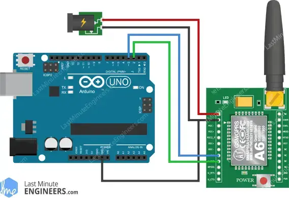
Wiring – Connecting the A6 GSM Module to an Arduino UNO
Now that we understand the module, we can connect it to our Arduino!
Serial Communication:
- Connect the U_TxD pin on the module to digital pin 3 on the Arduino.
- Connect the U_RxD pin on the module to digital pin 2 on the Arduino.
- We’ll use software serial to communicate with the module.
Power Supply:
- Connect the VCC pin on the module to an external 5V 2A power supply. Do not connect it to the Arduino’s 5V supply as it cannot provide sufficient current.
- Connect all ground pins in the circuit to ensure a common ground.
Antenna and SIM Card:
- Attach the antenna to the module.
- Insert a fully activated micro SIM card into the socket.
Alternative Power Supply:
- You can also power the module using a 5V 2A wall adapter.
- Ensure that the GND pin on the Arduino is connected to the GND pin on the module.

Powering Up:
- Once everything is connected, press the power key for about 2 seconds to turn on the module.
Always connect the GND pin before connecting the VCC pin and disconnect the VCC pin before the GND pin. Failing to do so can cause the module to use the low voltage serial pins as ground, which can damage the module instantly.
Parts Required
| Component Name | Buy Now |
| Arduino Uno REV3 | Amazon |
| SIM 900A Module Developemnt Board SMS/GSM/GPRS/STM32/A6 | Amazon |
Arduino Code – Testing AT Commands
To send AT commands and communicate with the A6 module, we will use the serial monitor. The following sketch enables the Arduino to communicate with the A6 module via the serial monitor. Before we dive into the code details, connect your Arduino to your PC, compile the code below, and upload it to the Arduino.
When you open the serial monitor, ensure that the ‘Both NL & CR’ option is selected!
#include <SoftwareSerial.h>

//Create software serial object to communicate with A6
SoftwareSerial mySerial(3, 2); //A6 Tx & Rx is connected to Arduino #3 & #2

void setup()
{
  //Begin serial communication with Arduino and Arduino IDE (Serial Monitor)
  Serial.begin(9600);

  //Begin serial communication with Arduino and A6
  mySerial.begin(9600);

  Serial.println("Initializing...");
  delay(1000);

  mySerial.println("AT"); //Once the handshake test is successful, it will back to OK
  updateSerial();
  mySerial.println("AT+CSQ"); //Signal quality test, value range is 0-31 , 31 is the best
  updateSerial();
  mySerial.println("AT+CCID"); //Read SIM information to confirm whether the SIM is plugged
  updateSerial();
  mySerial.println("AT+CREG?"); //Check whether it has registered in the network
  updateSerial();
}

void loop()
{
  updateSerial();
}

void updateSerial()
{
  delay(500);
  while (Serial.available())
  {
    mySerial.write(Serial.read());//Forward what Serial received to Software Serial Port
  }
  while(mySerial.available())
  {
    Serial.write(mySerial.read());//Forward what Software Serial received to Serial Port
  }
}
The sketch begins by including the SoftwareSerial.h library and initializing it with the Arduino pins connected to the A6 module’s Tx and Rx.
#include <SoftwareSerial.h>

//Create software serial object to communicate with A6
SoftwareSerial mySerial(3, 2); //A6 Tx & Rx is connected to Arduino #3 & #2
In the setup function, we initialize serial communication between the Arduino, Arduino IDE, and the A6 module at a baud rate of 9600.
//Begin serial communication with Arduino and Arduino IDE (Serial Monitor)
  Serial.begin(9600);

  //Begin serial communication with Arduino and A6
  mySerial.begin(9600);
Now that the basic connection is established, we communicate with the A6 module by sending AT commands.
- AT: The basic AT command, initializes auto-baud detection. If successful, it returns “OK”.
- AT+CSQ: Checks signal strength (0-31, with higher being better).
- AT+CCID: Retrieves the SIM card number to verify it is inserted correctly.
- AT+CREG?: Checks network registration status. A value of 1 indicates registration to the home network, and 5 indicates roaming.
  mySerial.println("AT"); //Once the handshake test is successful, it will back to OK
  updateSerial();
  mySerial.println("AT+CSQ"); //Signal quality test, value range is 0-31 , 31 is the best
  updateSerial();
  mySerial.println("AT+CCID"); //Read SIM information to confirm whether the SIM is plugged
  updateSerial();
  mySerial.println("AT+CREG?"); //Check whether it has registered in the network
  updateSerial();
In the loop, the updateSerial() function continuously checks for inputs from the serial monitor and forwards them to the A6 module. It also reads responses from the A6 module and forwards them to the serial monitor.
void updateSerial()
{
  delay(500);
  while (Serial.available())
  {
    mySerial.write(Serial.read());//Forward what Serial received to Software Serial Port
  }
  while(mySerial.available())
  {
    Serial.write(mySerial.read());//Forward what Software Serial received to Serial Port
  }
}
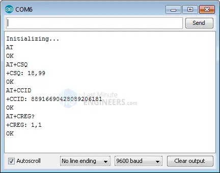
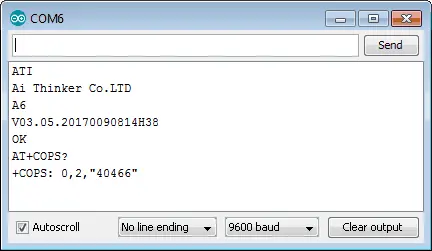
When you open the serial monitor, you should see the following output. You can now send additional commands through the serial monitor to get more information about the network connection:
- ATI: Get the module name and firmware revision.
- AT+COPS?: Check which network you are connected to (e.g., 40466 for BSNL).
- AT+COPS=?: Return a list of available operators in the network.
Arduino Code – Sending SMS
Let’s move on to an exciting task: programming our Arduino to send an SMS to any phone number. Before trying out the sketch, you need to enter the desired phone number. Look for the string ZZxxxxxxxxxx and replace ZZ with the country code and xxxxxxxxxx with the 10-digit phone number.
#include <SoftwareSerial.h>

//Create software serial object to communicate with A6
SoftwareSerial mySerial(3, 2); //A6 Tx & Rx is connected to Arduino #3 & #2

void setup()
{
  //Begin serial communication with Arduino and Arduino IDE (Serial Monitor)
  Serial.begin(9600);

  //Begin serial communication with Arduino and A6
  mySerial.begin(9600);

  Serial.println("Initializing...");
  delay(1000);

  mySerial.println("AT"); //Once the handshake test is successful, it will back to OK
  updateSerial();

  mySerial.println("AT+CMGF=1"); // Configuring TEXT mode
  updateSerial();
  mySerial.println("AT+CMGS=\"+ZZxxxxxxxxxx\"");//change ZZ with country code and xxxxxxxxxxx with phone number to sms
  updateSerial();
  mySerial.print("Last Minute Engineers | lastminuteengineers.com"); //text content
  updateSerial();
  mySerial.write(26);
}

void loop()
{
}

void updateSerial()
{
  delay(500);
  while (Serial.available())
  {
    mySerial.write(Serial.read());//Forward what Serial received to Software Serial Port
  }
  while(mySerial.available())
  {
    Serial.write(mySerial.read());//Forward what Software Serial received to Serial Port
  }
}
This sketch is similar to the previous one, with a few additional commands to send an SMS. Once the connection is established, we use the following AT commands:
- AT+CMGF=1: Selects the SMS message format as text. The default format is Protocol Data Unit (PDU).
- AT+CMGS=”+ZZxxxxxxxxxx”: Sends an SMS to the specified phone number. The text message is followed by a ‘Ctrl+Z’ character, which signals the end of the message. ‘Ctrl+Z’ corresponds to the 26th non-printing character in the ASCII table, so we need to send 26 (in decimal) or 1A (in hexadecimal) after the message.
  mySerial.println("AT+CMGF=1"); // Configuring TEXT mode
  updateSerial();
  mySerial.println("AT+CMGS=\"+ZZxxxxxxxxxx\"");//change ZZ with country code and xxxxxxxxxxx with phone number to sms
  updateSerial();
  mySerial.print("Last Minute Engineers | lastminuteengineers.com"); //text content
  updateSerial();
  mySerial.write(26);
The loop function is kept empty because we only want to send the SMS once. To send another SMS, just press the reset button on your Arduino. The screenshot below shows an SMS sent from the A6 GSM module.
Arduino Code – Reading SMS
Let’s program our Arduino to read incoming messages. This is particularly useful for triggering actions when specific SMS messages are received. For instance, the Arduino can turn a relay on or off based on an SMS command.
#include <SoftwareSerial.h>

//Create software serial object to communicate with A6
SoftwareSerial mySerial(3, 2); //A6 Tx & Rx is connected to Arduino #3 & #2

void setup()
{
  //Begin serial communication with Arduino and Arduino IDE (Serial Monitor)
  Serial.begin(9600);

  //Begin serial communication with Arduino and A6
  mySerial.begin(9600);

  Serial.println("Initializing...");
  delay(1000);

  mySerial.println("AT"); //Once the handshake test is successful, it will back to OK
  updateSerial();

  mySerial.println("AT+CMGF=1"); // Configuring TEXT mode
  updateSerial();
  mySerial.println("AT+CNMI=1,2,0,0,0"); // Decides how newly arrived SMS messages should be handled
  updateSerial();
}

void loop()
{
  updateSerial();
}

void updateSerial()
{
  delay(500);
  while (Serial.available())
  {
    mySerial.write(Serial.read());//Forward what Serial received to Software Serial Port
  }
  while(mySerial.available())
  {
    Serial.write(mySerial.read());//Forward what Software Serial received to Serial Port
  }
}
This sketch is similar to the previous one with a few additional commands to handle incoming SMS messages. Once the connection is established, we use the following AT commands:
- AT+CMGF=1: Selects the SMS message format as text. The default format is Protocol Data Unit (PDU).
- AT+CNMI=1,2,0,0,0: Specifies how new SMS messages should be handled. This command configures the A6 module to forward newly arrived SMS messages directly to the PC or save them in storage and notify the PC of their location.
The response to a new SMS starts with +CMT:. The fields in the response are comma-separated, with the first field being the phone number, the second field the sender’s name, the third field a timestamp, and the fourth field the actual message.
  mySerial.println("AT+CMGF=1"); // Configuring TEXT mode
  updateSerial();
  mySerial.println("AT+CNMI=1,2,0,0,0"); // Decides how newly arrived SMS messages should be handled
  updateSerial();
Unlike the previous sketch, the loop function is not empty this time because we are continuously polling for new SMS messages. Once you send an SMS to the A6 GSM module, you will see the output on the serial monitor.
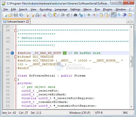
Expanding Arduino SoftwareSerial Buffer Size
If your message is long, you might receive it with some characters missing. This is not due to a faulty code but because the SoftwareSerial receive buffer is getting filled and discarding characters. The simplest solution is to increase the size of the SoftwareSerial buffer from its default size of 64 bytes to 512 bytes (or smaller, depending on what works for you).
On a Windows PC, go to C:\Program Files (x86)\Arduino\hardware\arduino\avr\libraries\SoftwareSerial (or src for newer versions of the Arduino IDE). Open SoftwareSerial.h and change the lin
// RX buffer size
#define _SS_MAX_RX_BUFF 64
to
// RX buffer size
#define _SS_MAX_RX_BUFF 512
Save the file and try your sketch again.
Arduino Code – Making Call
Let’s program the Arduino to make a phone call. This sketch is useful for emergency scenarios, such as making an SOS call if the temperature exceeds a certain threshold or if there is a break-in. You get the idea!
Before using the sketch, replace ZZxxxxxxxxxx with the appropriate country code and phone number.
#include <SoftwareSerial.h>

//Create software serial object to communicate with A6
SoftwareSerial mySerial(3, 2); //A6 Tx & Rx is connected to Arduino #3 & #2

void setup()
{
  //Begin serial communication with Arduino and Arduino IDE (Serial Monitor)
  Serial.begin(9600);

  //Begin serial communication with Arduino and A6
  mySerial.begin(9600);

  Serial.println("Initializing...");
  delay(1000);

  mySerial.println("AT"); //Once the handshake test is successful, i t will back to OK
  updateSerial();

  mySerial.println("ATD+ZZxxxxxxxxxx"); //  change ZZ with country code and xxxxxxxxxxx with phone number to dial
  updateSerial();
  delay(20000); // wait for 20 seconds...
  mySerial.println("ATH"); //hang up
  updateSerial();
}

void loop()
{
}

void updateSerial()
{
  delay(500);
  while (Serial.available())
  {
    mySerial.write(Serial.read());//Forward what Serial received to Software Serial Port
  }
  while(mySerial.available())
  {
    Serial.write(mySerial.read());//Forward what Software Serial received to Serial Port
  }
}
To make a call, the following AT commands are used:
- ATD+ZZxxxxxxxxxx;: Dials the specified phone number.
- ATH: Hangs up the call.
Replace the placeholder in the code with the actual phone number:
  mySerial.println("ATD+ZZxxxxxxxxxx"); //  change ZZ with country code and xxxxxxxxxxx with phone number to dial
  updateSerial();
  delay(20000); // wait for 20 seconds...
  mySerial.println("ATH"); //hang up
  updateSerial();
Once you upload this code to your Arduino, it will dial the specified number, wait for 20 seconds, and then hang up. The following screenshot shows a call made from the A6 GSM module.


Arduino Code – Receiving Call
To receive a call, you don’t need special code; just listen to the A6 module. However, the following sketch can be helpful if you want to trigger an action when a call from a specific number is received.
#include <SoftwareSerial.h>

//Create software serial object to communicate with A6
SoftwareSerial mySerial(3, 2); //A6 Tx & Rx is connected to Arduino #3 & #2

void setup()
{
  //Begin serial communication with Arduino and Arduino IDE (Serial Monitor)
  Serial.begin(9600);

  //Begin serial communication with Arduino and A6
  mySerial.begin(9600);

  Serial.println("Initializing...");
}

void loop()
{
  updateSerial();
}

void updateSerial()
{
  delay(500);
  while (Serial.available())
  {
    mySerial.write(Serial.read());//Forward what Serial received to Software Serial Port
  }
  while(mySerial.available())
  {
    Serial.write(mySerial.read());//Forward what Software Serial received to Serial Port
  }
}
Incoming calls are indicated by “RING” on the serial monitor, followed by the caller’s phone number and ID. The following AT commands are used to manage calls:
- ATA: Accepts the incoming call.
- ATH: Hangs up the call. When the call is ended, “NO CARRIER” appears on the serial monitor, indicating the call was disconnected.
Here is an example of receiving a call with the A6 GSM module shown on the serial monitor.
- Arduino and GPS: How to Interface NEO-6M Module
- Arduino HC-05 Bluetooth Module Tutorial: Step-by-Step Guide
- Mastering Bluetooth Low Energy with ESP32 (BLE)
- ESP32 Essentials: Exploring the Power of Bluetooth Classic


