

Bluetooth has become ubiquitous in today’s world. It’s a term we encounter frequently and is integrated into millions of everyday products such as headsets, cellphones, laptops, game controllers, and activity trackers.
In the realm of embedded electronics, Bluetooth provides an excellent means of wirelessly transmitting small amounts of data over short distances (typically less than 100 meters). It facilitates real-time data logging and enables smartphone control of projects.
Among the most cost-effective and commonly utilized Bluetooth modules is the HC-05, available online for approximately $5. It presents an economical solution for incorporating Bluetooth connectivity into projects, eliminating the hassle of tangled cables and cluttered wires.
This tutorial aims to introduce you to the HC-05. To prevent overwhelming you with information, we’ll divide the tutorial into three manageable parts. The first section will demonstrate how to send and receive data between the HC-05 and your smartphone. Subsequently, we’ll delve into configuring the HC-05 using AT commands in the second tutorial. Finally, the third tutorial will guide you through establishing wireless communication between two Arduino boards utilizing HC-05 Bluetooth modules.
Upon completing these tutorials, you’ll possess a solid understanding of utilizing the HC-05 Bluetooth module in your projects. Let’s begin!
Parts Required
| Component Name | Buy Now |
| Arduino Uno REV3 | Amazon |
| HC-05 Bluetooth Serial Pass-through Module | Amazon |
| 5V One Channel Relay Module | Amazon |
| Breadboard Set | Amazon |
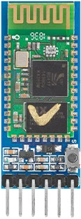
HC-05 Hardware Overview
The HC-05 serves as a Bluetooth-to-Serial-Bridge module facilitating wireless communication between two microcontrollers or between a microcontroller and devices such as smartphones, laptops, or desktop PCs equipped with Bluetooth capability. It’s an ideal solution for directly substituting a wired asynchronous serial interface.
Each module incorporates a Bluetooth transceiver, enabling both data transmission and reception.
Operating as a Class 2 Bluetooth device, the HC-05 boasts a nominal range of 10 meters, though this range may diminish indoors due to obstructions like walls.
Moreover, these modules are exceptionally user-friendly. There’s no requirement to navigate Bluetooth protocols or stacks. Simply transmit data over a serial interface, and it seamlessly transfers to the connected Bluetooth device.
Modes of Operation
Operating the HC-05 module and transmitting data through it involve distinct processes, both executed via the serial interface. To differentiate between these operations, the HC-05 employs two separate communication modes: AT mode and Data mode.
In AT Mode, users can adjust various settings of the HC-05 module, such as its name, baud rate, PIN code, and data rate.
Data Mode transforms the HC-05 module into a transparent data gateway. Upon receiving data, the HC-05 removes Bluetooth headers and trailers, forwarding it to the UART port. Conversely, data written to the UART port prompts the HC-05 to construct a Bluetooth packet, transmitting it over the Bluetooth wireless connection.
Connection Roles
The HC-05 Bluetooth module functions in two primary roles: Master and Slave.
In the Slave Role, the HC-05 module awaits connection initiation from other devices. This default role is commonly utilized in projects requiring smartphone-controlled operations.
Conversely, the Master Role entails the HC-05 actively seeking other Bluetooth devices and initiating connections. This mode suits projects necessitating wireless communication between two microcontrollers.
Role switching entails configuring the HC-05 module by activating AT mode and transmitting AT commands via the UART port.
Power
The bare HC-05 chip operates at a maximum voltage of 3.3V. Therefore, the module integrates a linear 3.3V regulator, enabling a power supply voltage range of 3.6V to 6V.
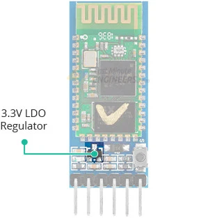
Crucially, the HC-05 module operates at a 3.3V logic level. Consequently, directly connecting the HC-05 module’s Rx pin to a digital pin on a 5V microcontroller like an Arduino UNO is infeasible. The Rx pin on the HC-05 module lacks 5V tolerance, necessitating the reduction of the microcontroller’s Tx signal to 3.3V before connecting to the HC-05 module.
The HC-05 module’s current consumption varies depending on its operational state, as outlined in the datasheet.
| Mode | Current Consumption |
| Connected with data transfer | 45 mA |
| Connected Idle | 8 mA |
Status LED
Many HC-05 modules feature an onboard LED indicating various statuses:
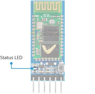
- Upon powering up, the module enters Bluetooth pairing mode, with the LED flashing rapidly at approximately 2 Hz.
- Once paired with a device, the LED flash pattern shifts to two quick flashes, followed by a pause, repeating.
- AT Mode activation prompts the LED to blink at a slow, steady rate.
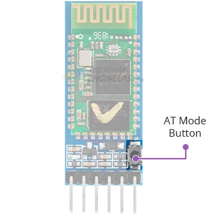
AT Mode
AT Mode facilitates configuration adjustments by enabling users to send Hayes AT-style commands to the HC-05 module, altering settings like name, baud rate, and password.
Typically, the HC-05 module operates in data mode. Transitioning it to AT mode involves pressing and holding the onboard button while powering up the module. The LED then blinks at a slow, steady rate, indicating AT mode activation.
Once in AT mode, users can transmit AT commands to the module via the UART port. The module responds to commands by acknowledging, providing requested data, or signaling errors. Commands usually commence with “AT+” followed by the specific command (e.g., “AT+NAME?” queries the module’s name, while “AT+NAME=MyHC05” changes it to “MyHC05”).
AT commands should be transmitted at the specified baud rate for AT mode, which may differ from the Data mode baud rate.
HC-05 Pinout
The HC-05 module features six pins, each serving distinct functions. Let’s examine the pinout:
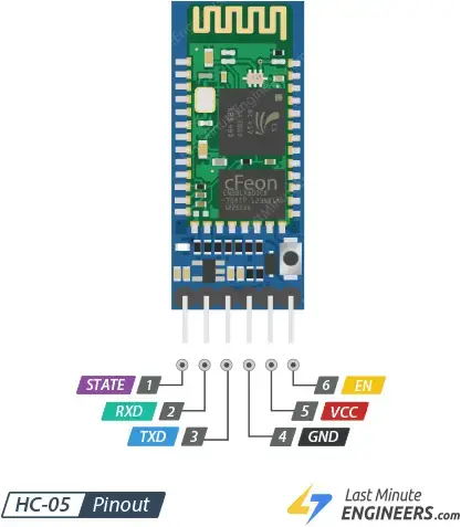
The STATE pin serves to ascertain the current status of the HC-05 module. It remains in a LOW state when the module is unpaired and switches to a HIGH state once paired.
The RXD pin is designated for receiving serial data from the microcontroller. It should be linked to the microcontroller’s TX pin. It’s important to note that this pin lacks 5V tolerance. Therefore, prior to connecting the module to a 5V microcontroller, the microcontroller’s TX signal must be reduced to 3.3V.
Conversely, the TXD pin is utilized for transmitting serial data to the microcontroller. It should be connected to the microcontroller’s RX pin.
GND serves as the ground pin, providing a common ground for all devices connected to the module.
VCC is where the positive supply voltage is connected. This voltage signal is directed to the HC-05 chip through a 3.3V regulator, with the voltage ranging between 3.6V and 6V.
The EN pin is linked to the on-board regulator enable pin and is pulled high by a 220k resistor. Pulling this pin low disables the regulator, consequently powering off the HC-05 module.
Controlling the HC-05 Module
To control the HC-05 Bluetooth module and transmit data through it, all you need is a serial interface. It essentially functions as a conduit for data: serial data inputted into the module (via the RXD pin) is relayed through the Bluetooth connection, while data received from the Bluetooth side is transmitted through the serial interface (via the TXD pin).
To establish this data conduit, we follow a two-step process:
- Connect the HC-05 module to a device capable of sending and receiving serial data, such as an Arduino or any microcontroller equipped with UART.
- On the Bluetooth side, initiate a wireless connection between the HC-05 module and another Bluetooth-enabled device, like an Android phone. This connection entails a pairing procedure akin to linking any two Bluetooth devices. Additionally, you’ll need a terminal program installed on your phone capable of Bluetooth communication. We recommend using “Serial Bluetooth Terminal,” available on the Play Store, though there are numerous other free options to explore.
In essence, by establishing the serial interface between the HC-05 and our microcontroller, and subsequently pairing the HC-05 with the other Bluetooth device, we’re ready to operate seamlessly!
Wiring a HC-05 Module to an Arduino
Connecting the HC-05 Module to an Arduino is straightforward: apply power and wire up the serial RX and TX pins.
Rather than linking the HC-05 Module directly to the Arduino’s hardware UART, we’ll utilize SoftwareSerial and connect the HC-05’s RX and TX pins to any available digital pins on the Arduino. This approach prevents bus contention and ensures that the HC-05 doesn’t inadvertently receive data during sketch uploads.
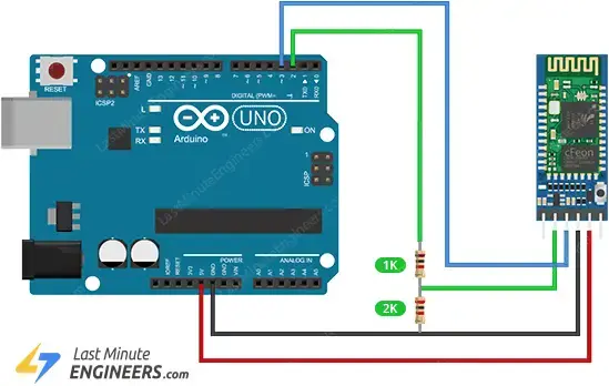
Therefore, connect the HC-05 module’s TXD to Arduino’s D3, RXD to D2, GND to GND, and VCC to 5V. The TXD and RXD pins can be linked to any digital pin (except 0 and 1). Thus, if pins 2 and 3 are already allocated for other functions, they can be swapped.
However, it’s crucial to remember that the Rx pin on the HC-05 module lacks 5V tolerance. Consequently, direct connection of HC-05’s Rx pin to the Arduino’s digital pin (5V MCU) is not feasible. The Tx signal from the Arduino must be reduced to 3.3V. One simple method to achieve this is by employing a resistor divider. Using a 1K resistor between HC-05’s Rx and Arduino’s D2, and a 2K resistor between HC-05’s Rx and GND, will suffice.
In summary, the following connections will be established for the example code provided later in this tutorial:
| HC-05 Module | Arduino | Notes |
| VCC | 5V | – |
| GND | GND | – |
| TXD | D3 | – |
| RXD | D2 | Use level shifter if using 5V MCU |
The image below shows how to connect the HC-05 module to the Arduino Uno.
Bluetooth Serial Passthrough Sketch
With a little ingenuity, we can use the Arduino as a medium between us and the HC-05 module. Below is a simple sketch that relays data between the Arduino Serial Monitor and the HC-05 module.
#include <SoftwareSerial.h>
//Create software serial object to communicate with HC-05
SoftwareSerial mySerial(3, 2); //HC-05 Tx & Rx is connected to Arduino #3 & #2
void setup()
{
//Begin serial communication with Arduino and Arduino IDE (Serial Monitor)
Serial.begin(9600);
//Begin serial communication with Arduino and HC-05
mySerial.begin(9600);
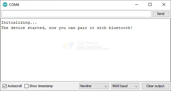
Serial.println("Initializing...");
Serial.println("The device started, now you can pair it with bluetooth!");
}
void loop()
{
if(Serial.available())
{
mySerial.write(Serial.read());//Forward what Serial received to Software Serial Port
}
if(mySerial.available())
{
Serial.write(mySerial.read());//Forward what Software Serial received to Serial Port
}
delay(20);
}
Once you have uploaded the sketch, open the serial monitor at baud rate 9600. You should see a message saying: “The device started, now you can pair it with bluetooth!”.
Connecting to the Android Phone
Let’s establish a wireless link between the HC-05 module and an Android phone. The procedure might vary depending on the device, but the general steps remain similar.
- Ensure the HC-05 module is powered on and ready to establish a connection. The onboard LED should blink rapidly at approximately 2 Hz, indicating its discoverability.
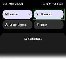
- Swipe down from the top of your Android phone’s screen and confirm Bluetooth is enabled.
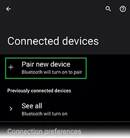
- Long-press the Bluetooth icon, then select “Pair new device” and wait briefly.
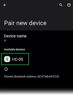
- Choose the name of the Bluetooth device you wish to pair with your phone (e.g., HC-05). Follow any on-screen prompts.
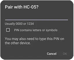
- When prompted, input “1234” as the PIN code. This is the default PIN for all HC-05 modules.
For the subsequent steps in this guide, you’ll need a Bluetooth Terminal application installed on your smartphone. We recommend using the “Serial Bluetooth Terminal” Android app, available on the Play Store.
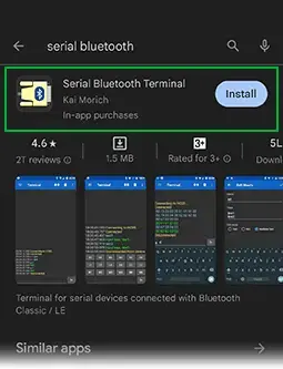
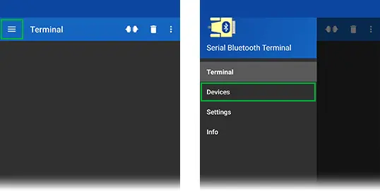
- Once installed, open the “Serial Bluetooth Terminal” app. Tap the icon in the top left corner and select “Devices”.
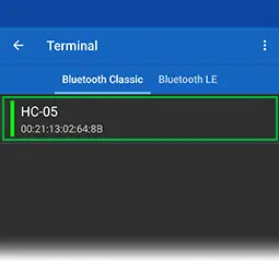
- You should see a list of previously paired devices. Choose “HC-05” from this list.
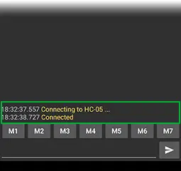
- Upon successful connection, you’ll receive a “Connected” notification. The flash pattern of your HC-05’s onboard LED should change to two quick flashes followed by a pause. Your smartphone is now paired with the HC-05 Bluetooth module and ready for communication.
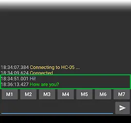
- Now, enter a message in the input box at the bottom of the app, such as “Hi!”
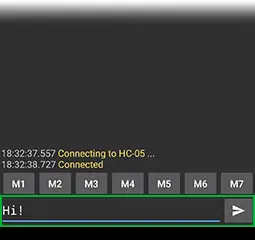
- You should promptly receive the message in the Arduino IDE Serial Monitor.

- You can also exchange data between your Serial Monitor and smartphone. Input a message in the Serial Monitor’s top input box and press “Send”.
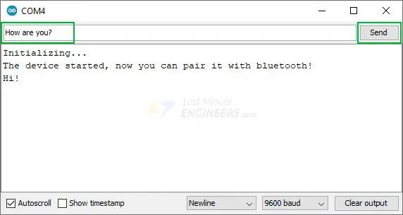
- The message should instantly appear in the Serial Bluetooth Terminal App.
Arduino Project: Bluetooth-Controlled Relay
Let’s embark on a straightforward project that enables wireless relay control via Bluetooth. This application can prove handy for tasks like home automation, managing smart lighting, enhancing security systems, and other similar endeavors.
For this project, we’ll employ a two-channel relay module. If you’re unfamiliar with it, it’s advisable to peruse the tutorial provided below.
Wiring
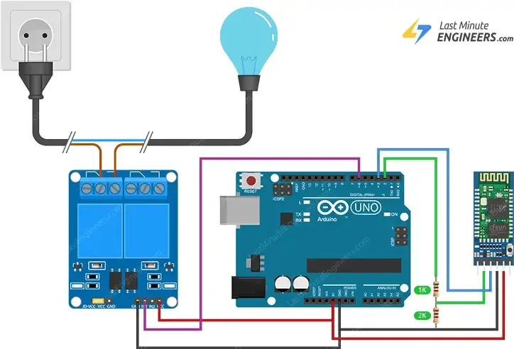
We’ll utilize the identical Arduino setup as in the preceding example, but this time we’ll incorporate a two-channel relay module to control a lamp.
Refer to the image below for guidance on constructing the circuit.
Arduino Code
Once you are done with the wiring, try the below sketch.
#include <SoftwareSerial.h>

// GPIO where relay is connected to
const int relayPin =  6;

// Handle received messages
String message = "";

// Create software serial object to communicate with HC-05
SoftwareSerial mySerial(3, 2); //HC-05 Tx & Rx is connected to Arduino #3 & #2

void setup() {
  // Begin serial communication with Arduino and Arduino IDE (Serial Monitor)
  Serial.begin(9600);

  // Initialize relayPin as an output
  pinMode(relayPin, OUTPUT);
  digitalWrite(relayPin, HIGH);

  //Begin serial communication with Arduino and HC-05
  mySerial.begin(9600);

  Serial.println("Initializing...");
  Serial.println("The device started, now you can pair it with bluetooth!");
}

void loop() {
  if (mySerial.available()){
    char incomingChar = mySerial.read();
    if (incomingChar != '\n'){
      message += String(incomingChar);
    }
    else{
      message = "";
    }
    Serial.write(incomingChar);
  }
  // Check received message and control output accordingly
  if (message == "on"){
    digitalWrite(relayPin, LOW);
  }
  else if (message == "off"){
    digitalWrite(relayPin, HIGH);
  }
  delay(20);
}
Testing the Code
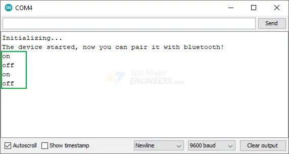
Once you’ve uploaded the sketch, open the serial monitor at a baud rate of 9600. You’ll observe a message stating: “The device started, now you can pair it with Bluetooth!”.

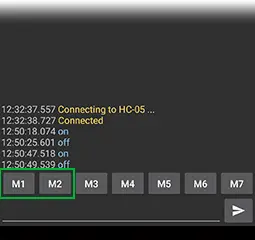
Next, launch the Serial Bluetooth Terminal app and establish a connection with your HC-05 module.
Now, when you input “on” in the bottom input box of the app, the relay will promptly activate. Similarly, typing “off” will instantly deactivate the relay.
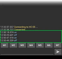
Furthermore, for monitoring purposes, these messages will also be displayed in the Arduino IDE Serial Monitor.
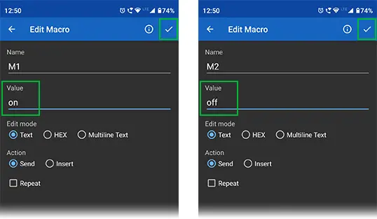
The app provides various macros that you can customize to save default messages. For example, you can assign M1 to the “on” message and M2 to the “off” message. This enables easy relay control using the predefined buttons, enhancing the convenience of your project.
Going Further
This tutorial aims to equip you for an exciting venture into the realm of Bluetooth. With a solid understanding of how to exchange data between the HC-05 and your smartphone, you’re now ready to delve deeper by learning how to configure the HC-05 using AT commands.
Additionally, you can explore how to establish wireless communication between two Arduino boards using HC-05 Bluetooth modules, unlocking even more possibilities for your wireless projects.
Related article
- Mastering AT Commands for HC-05 Configuration
- MAX4466 Microphone Module: Arduino Interface Guide
- Step-by-Step Guide: HC-SR501 PIR Sensor Working Principles and Arduino Integration
- Understanding the Operation of HC-SR04 Ultrasonic Sensor and Connecting it to Arduino
- DIY Project: Arduino Interface for TFMini-S LiDAR Sensor


So, where exactly does the 5V one channel relay come into play?