
This MAX4466 module boasts a sophisticated design, featuring adjustable gain and versatile supply voltage options, rendering it suitable for a diverse array of audio applications. Ideal projects for this module include real-time voice modulation, audio recording and sampling, as well as audio-reactive endeavors employing Fast Fourier Transform (FFT) algorithms.
Within a microphone lies a delicate diaphragm positioned opposite a backplate, collectively forming a capacitor.
When sound waves from your voice reach the microphone, they cause the diaphragm to oscillate.
As the diaphragm oscillates, it moves closer to or farther away from the backplate, altering the capacitance between them. This variance in capacitance generates a voltage across the plates, which can be quantified to ascertain the sound’s magnitude.
Parts Required
| Component Name | Buy Now |
| Arduino Uno REV3 | Amazon |
| Microphone Amplifier MAX4466 Module | Amazon |
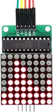
| MAX7219 8×8 Dot Matrix LED Display Module | Amazon |
| Breadboards Kit | Amazon |
Module Overview
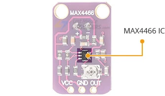
At the heart of this module lies the Maxim MAX4466 micropower op-amp, purposefully engineered for microphone amplification. Renowned for its remarkable common-mode rejection and superior power-supply rejection ratio, the MAX4466 stands as an optimal choice for environments prone to noise interference. Consequently, this amplifier ensures pristine sound quality, devoid of the typical noise or distortion encountered in other microphone amplifier modules.
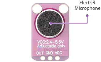
In addition to the MAX4466, the module houses an electret microphone capable of capturing sound frequencies spanning from 20 Hz to 20 kHz, along with essential supporting circuitry to drive the op-amp.
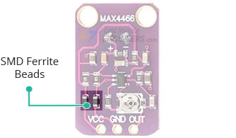
Furthermore, SMD ferrite beads integrated into the module serve to suppress electromagnetic emissions. These beads, connected in series with the power supply rails, effectively mitigate low-frequency noise and absorb high-frequency noise, thereby augmenting the common-mode rejection ratio.
Located on the module’s rear is a small trimmer potentiometer employed for gain adjustment. The gain setting dictates the extent to which the module amplifies the incoming sound signal. Rotating the potentiometer counterclockwise increases the gain, while clockwise rotation decreases it.
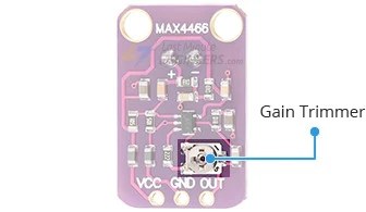
The gain can be adjusted within a range of 25x to 125x. At the minimum setting, the module amplifies to approximately 200 mVpp (suitable for normal speaking volumes from a distance of about 6 inches)—ideal for interfacing with devices expecting ‘line level’ input without clipping. At the upper limit, it can amplify up to roughly 1Vpp, ideal for interfacing with a microcontroller’s ADC. It’s important to note that the output is rail-to-rail, meaning that under high sound pressure levels, the output can reach up to 5 Vpp!
Utilizing the module is straightforward: connect the GND pin to ground and the VCC pin to a power source between 2.4-5VDC. The audio waveform will be outputted from the OUT pin, which can be directly connected to the microcontroller’s ADC pin. It’s essential to acknowledge that the output will feature a DC bias equivalent to VCC/2, maintaining a steady voltage level of VCC/2 during periods of silence.
MAX4466 Module Pinout
The module has three pins.
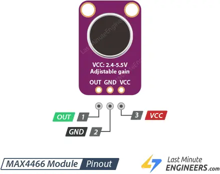
- VCC is the power supply pin that accepts 2.4V to 5.5V DC voltage.
- GND is the ground pin.
- OUT is the analog output pin that delivers the amplified sound signal. Please note that the output will have a DC bias equal to VCC/2, so when it’s perfectly quiet, the voltage will remain steady at a VCC/2 level.
Connecting a MAX4466 Module to an Arduino
The connection process is straightforward, requiring only three wires to be linked: two for power and one for output.
The VCC of the MAX4466 module operates within a range of 2.4-5VDC. For optimal functionality, it’s advisable to utilize the 3.3V pin on the Arduino, as it offers the most stable power supply. Consequently, power the sensor using 3.3V and establish a ground connection. Subsequently, connect the output to an analog input pin; for this demonstration, we’ll utilize pin A0.
Below is a table detailing the pin connections:
| MAX4466 Module | Arduino |
| VCC | 3.3V |
| GND | GND |
| OUT | A0 |
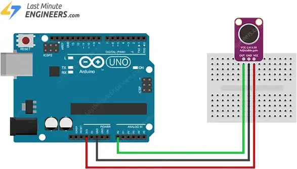
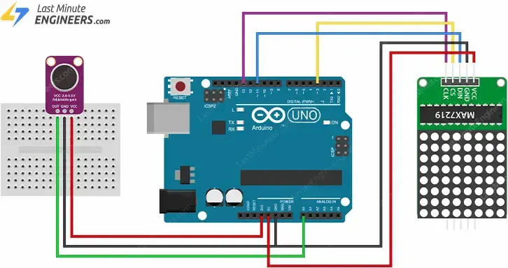
The wiring is shown in the image below.
Arduino Code Example – Sound Level Measurement
The output signal from the MAX4466 amplifier manifests as a varying voltage. To gauge the sound level accurately, it’s imperative to take multiple measurements to ascertain the minimum and maximum values, known technically as the ‘peak-to-peak amplitude’ of the signal.
In the provided code snippet, we’ve selected a sample window of 50 milliseconds. This duration proves adequate for capturing sound levels across frequencies as low as 20 Hz, the threshold of human auditory perception. After identifying the minimum and maximum samples, we calculate the difference (yielding the peak-to-peak amplitude of the sound) and convert it into volts. The resultant value is then displayed on the serial monitor.
const int sampleWindow = 50; // Sample window width in mS (50 mS = 20Hz)
int const AMP_PIN = A0; // Preamp output pin connected to A0
unsigned int sample;
void setup()
{
Serial.begin(9600);
}
void loop()
{
unsigned long startMillis = millis(); // Start of sample window
unsigned int peakToPeak = 0; // peak-to-peak level
unsigned int signalMax = 0;
unsigned int signalMin = 1024;
// collect data for 50 mS and then plot data
while (millis() - startMillis < sampleWindow)
{
sample = analogRead(AMP_PIN);
if (sample < 1024) // toss out spurious readings
{
if (sample > signalMax)
{
signalMax = sample; // save just the max levels
}
else if (sample < signalMin)
{
signalMin = sample; // save just the min levels
}
}
}
peakToPeak = signalMax - signalMin; // max - min = peak-peak amplitude
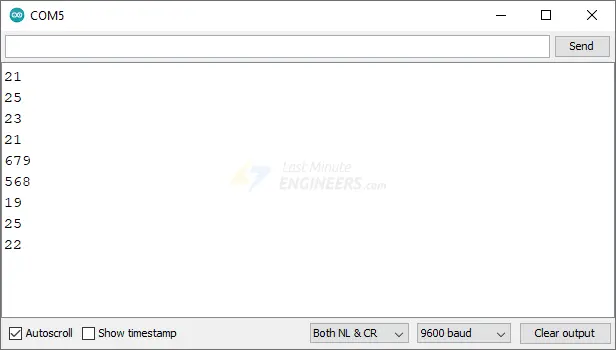
Serial.println(peakToPeak);
//double volts = (peakToPeak * 5.0) / 1024; // convert to volts
//Serial.println(volts);
}
Upon uploading the sketch, navigate to the serial monitor and configure the baud rate to 9600. Now, experiment by snapping your fingers in proximity to the sensor; you’ll notice fluctuations in the readings.
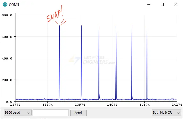
Visualizing serial data solely through numerical values can be challenging. For users employing Arduino IDE v1.6.6 or newer, an alternative option is available: the Arduino Serial Plotter.
To access the Serial Plotter in the Arduino IDE, navigate to Tools > Serial Plotter. When you snap your fingers near the sensor, you should observe a waveform akin to the illustration below.
Explanation of the Code:
The code commences by establishing various constants and variables.
Initially, a constant named sampleWindow is declared, determining the width of the sample window in milliseconds. It’s set to 50, corresponding to a frequency of 20 Hz. Following that, another constant, AMP_PIN, is defined, indicating the analog pin A0 to which the output from the MAX4466 module is connected. Additionally, an unsigned integer variable named sample is initialized to store the values obtained from AMP_PIN.
const int sampleWindow = 50;  // Sample window width in mS (50 mS = 20Hz)
int const AMP_PIN = A0;       // Preamp output pin connected to A0
unsigned int sample;
In the setup() function, the Serial Monitor is initiated for debugging purposes.
void setup() {
  Serial.begin(9600);
}
At the onset of the loop() function, the current time (in milliseconds since the Arduino’s initiation) is recorded in the variable startMillis.
unsigned long startMillis= millis();
Subsequently, the variables peakToPeak, signalMax, and signalMin are initialized. peakToPeak will hold the disparity between the maximum and minimum values detected from the microphone, representing the sound’s amplitude. signalMax and signalMin are employed to retain the highest and lowest values detected from the microphone during the sampling window, respectively.
unsigned int peakToPeak = 0;
unsigned int signalMax = 0;
unsigned int signalMin = 1024;
The while loop continues as long as the difference between the present time and startMillis is less than sampleWindow (50 milliseconds in this instance). This loop is utilized to read the microphone’s output and identify the highest and lowest values within this timeframe. Within the loop, the voltage at AMP_PIN is read using analogRead() and stored in the sample variable. If the sample is valid (i.e., not spurious) and greater than signalMax, it updates signalMax; if the sample is less than signalMin, it updates signalMin.
while (millis() - startMillis < sampleWindow)
{
  sample = analogRead(AMP_PIN);
  if (sample < 1024)  // toss out spurious readings
  {
    if (sample > signalMax)
    {
      signalMax = sample;  // save just the max levels
    }
    else if (sample < signalMin)
    {
      signalMin = sample;  // save just the min levels
    }
  }
}
Once the sampling window concludes, the disparity between signalMax and signalMin is computed to determine the peak-to-peak amplitude of the sound. This value is stored in peakToPeak.
peakToPeak = signalMax - signalMin;
Subsequently, the peakToPeak value is printed to the Serial monitor.
Serial.println(peakToPeak);
The commented-out lines at the code’s conclusion convert the peak-to-peak amplitude of the sound into volts. This can be advantageous if a voltage representation of the amplitude is desired.
//double volts = (peakToPeak * 5.0) / 1024;  // convert to volts
//Serial.println(volts);
Arduino Project – Scrolling Sound Level Meter
Alright, that initial demonstration wasn’t exactly thrilling. Let’s kick it up a notch by utilizing the peak-to-peak measurement to regulate a MAX7219-based LED Matrix, showcasing the sound level. To add an extra layer of intrigue, we’ll implement a scrolling display to graph the last 8 measurements in real-time.
If you’re unfamiliar with the MAX7219 LED Dot Matrix Display, it’s advisable to peruse the tutorial provided below.
Hardware Connection
Refer to the illustration below for building the circuit.
The subsequent tables detail the pin connections:
| MAX4466 Module | Arduino |
| VCC | 3.3V |
| GND | GND |
| OUT | A0 |
| MAX7219 Module | Arduino |
| VCC | 5V |
| GND | GND |
| DIN | 11 |
| CS/LOAD | 10 |
| CLK | 13 |
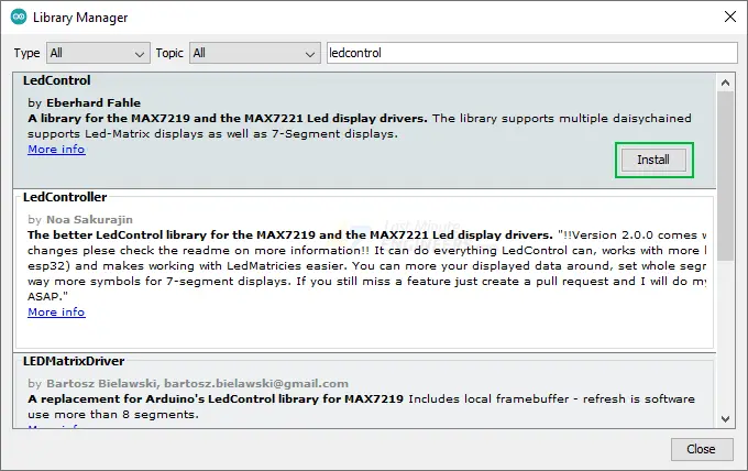
Installing the LedControl Library
In order to interface with the MAX7219 chip, you’ll require a library. The LedControl library developed by Eberhard Fahle is highly recommended for this purpose. This library offers a comprehensive set of functions for controlling each LED independently, a feature that proves invaluable for our project.
To install the library, navigate to Sketch > Include Library > Manage Libraries… Allow the Library Manager to download the libraries index and update the list of installed libraries.
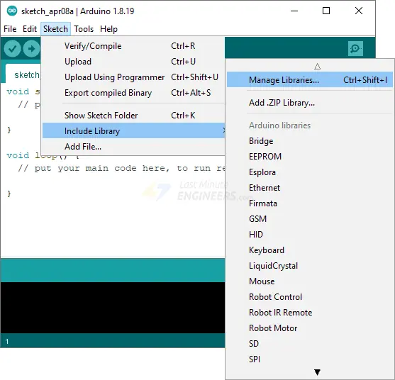
Filter your search by typing ‘ledcontrol’. Locate the LedControl by Eberhard Fahle. Click on the entry and select Install.
Uploading the Code
Copy and paste the following code into the Arduino IDE and upload it.
#include "LedControl.h"

int displayCnt = 1;  // # of displays connected (between 1-8)
int intensity = 1;   // Brightness of displays (between 0-15)

LedControl lc = LedControl(11, 13, 10, displayCnt);  // Pins: DIN, CLK, CS, # of Displays

const int maxScale = 8;
const int sampleWindow = 50; // Sample window width in mS (50 mS = 20Hz)
unsigned int sample;

byte columnData[8] = {0, 0, 0, 0, 0, 0, 0, 0};  // To store the 8 column data

void setup() {
  for (int idx = 0; idx < displayCnt; idx++) {
    lc.shutdown(idx, false);  // Wake up displays
    lc.setIntensity(idx, intensity);  // Set intensity levels
    lc.clearDisplay(idx);  // Clear Displays
  }
}

void loop() {
  unsigned long startMillis = millis();
  unsigned int peakToPeak = 0;
  unsigned int signalMax = 0;
  unsigned int signalMin = 1024;

  while (millis() - startMillis < sampleWindow) {
    sample = analogRead(0);
    if (sample < 1024) {
      if (sample > signalMax) {
        signalMax = sample;
      } else if (sample < signalMin) {
        signalMin = sample;
      }
    }
  }
  peakToPeak = signalMax - signalMin;
  int displayPeak = map(peakToPeak, 0, 512, 0, maxScale);

  // Shift column data in the array
  for (int i = 0; i < 7; i++) {
    columnData[i] = columnData[i + 1];
  }

  // Create new measurement column
  byte newData = 0;
  for (int i = 0; i < displayPeak; i++) {
    newData |= (1 << i);
  }
  columnData[7] = newData;

  // Update the display
  for (int col = 0; col < 8; col++) {
    lc.setColumn(0, col, columnData[col]);
  }

  delay(100);
Demonstration
Next, attempt to speak in a normal voice while positioned approximately 6–8 inches away from the microphone. You should observe the sound level meter matrix display commence scrolling.
Related article
- MAX6675 Thermocouple Module: Seamless Integration with Arduino
- Distance Measurement with ESP32: HC-SR04 Ultrasonic Sensor Guide
- MPU6050 Accelerometer: Seamless Connection to Arduino Explained
- Mastering AT Commands for HC-05 Configuration


