
If you wish to gauge temperature using an Arduino, there are numerous sensor options available. Some popular choices include the DHTxx series, DS18B20, LM35, and TMP36, each providing distinct features tailored to your specific project requirements.
However, what if your temperature measurement needs extend to extremely high temperatures, like those found in a volcano (exceeding 1000°C or 1800°F), or extremely low temperatures, such as those encountered with liquid nitrogen (approximately −195.8 °C or −320 °F)? In such scenarios, conventional temperature sensors would either melt or freeze completely.
So, how can you measure the temperature of extremely hot or cold objects? Enter the thermocouple, a clever pair of electric cables. A thermocouple is a type of temperature sensor that utilizes the thermoelectric effect to measure temperatures ranging from -330°F to +2460°F.
This tutorial will walk you through the process of interfacing the MAX6675 thermocouple module—an extensively used, cost-effective, yet precise thermocouple module—with an Arduino. But before we delve into that, let’s briefly review the fundamentals of thermocouples.
Thermocouple Fundamentals
A thermocouple consists of two metal wires that are different from each other (the term “dissimilar” denotes this difference).
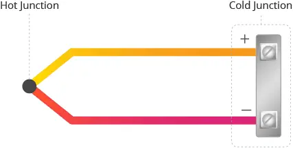
These metal wires are joined at a single point, typically at the tip of the thermocouple, known as the Hot Junction, Measurement Junction, Sensing Point, or Sensing Junction. As the name suggests, this junction is exposed to the heat source under consideration.
The opposite end of the metal wires is referred to as the Cold Junction and is connected to the measuring device. Generally, the cold junction is not subjected to the same level of thermal energy as the hot junction.
Thermoelectric Effect
All thermocouples operate on the same principle—they produce a small voltage when exposed to heat.
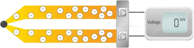
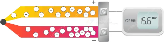
When a piece of metal is heated, the heat excites the electrons in the metal, causing them to move. With increasing temperature, more electrons tend to “diffuse” and move toward the cooler end of the metal.
This results in the hotter end becoming slightly positively charged and the cooler end slightly negatively charged, creating a voltage difference. This phenomenon is known as the Thermoelectric Effect or Seebeck Effect, named after the German scientist Thomas Seebeck, who discovered it in 1821.
Functioning of Thermocouples
A thermocouple functions based on the movement of electrons in its metal wires caused by the temperature difference between the hot and cold junctions.
If both wires of the thermocouple were made of the same metal, such as copper, electrons in both wires would move away from the heat and accumulate at the cold ends in equal amounts, leading to no measurable voltage difference.
However, thermocouples are composed of two different types of metal wire. For instance, if one wire is made of copper and the other of iron, the metals conduct heat differently, creating a distinct temperature gradient. This results in varying electron buildup at the cold ends, generating a measurable voltage difference.
This voltage difference is very small, with the actual change in voltage per degree Celsius being minuscule. For a Type-K thermocouple, the change is approximately 41 µV/°C.
Thermocouple Wire Leads
When subjected to heat, electrons in each thermocouple wire react differently and move at different rates.
The wire with more accumulated electrons at the cold junction is termed the negative wire lead, while the one with fewer electrons at the cold junction is termed the positive wire lead.
This difference in charge between the positive and negative wire leads can be measured and used to determine the temperature at the hot junction.
Type-K Thermocouple
Various types of thermocouples exist, such as Type-J, Type-K, Type-E, Type-T, etc., based on the combination of metals or alloys used for the two wires. Each type has its characteristic function, temperature range, accuracy, and application.
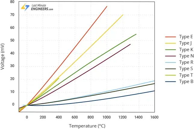
Type-K is the most widely used thermocouple in industrial applications due to its predictable response over a wide temperature range (around -328 °F to +2300 °F) and sensitivity of about 41 μV/°C. It comprises a positive wire made of Chromel (nickel-chromium alloy) and a negative wire made of Alumel (nickel-aluminum alloy).
Thermocouple Digitizer
To make the thermocouple practical, calibration is necessary by testing it against known temperatures and recording the generated voltages. A formula can then be used to calculate the temperature based on the measured voltage.
This is where thermocouple digitizer integrated circuits (ICs), like the MAX6675 IC, come into play. These ICs are designed to perform cold-junction compensation and digitize the signal received from a thermocouple.
MAX6675 Thermocouple Module
The MAX6675 thermocouple module typically comprises a MAX6675 breakout board and a Type-K thermocouple probe. Let’s explore them in more detail.
MAX6675 Breakout
At the heart of the breakout is the MAX6675, a cold-junction-compensated Type-K thermocouple digitizer IC from Microchip.
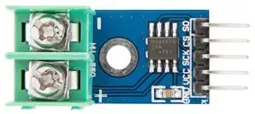
The breakout takes a standard Type-K thermocouple at one end, digitizes the measured temperature, and transmits the data through an SPI interface, facilitating easy interpretation for reading!
The MAX6675 IC integrates a 12-bit analog-to-digital converter (ADC), offering a resolution of 0.25°C (12-bit resolution).
With the capability to measure temperatures from 0 °C to +1024 °C and an accuracy of ±3 °C, the MAX6675’s range depends on the type of probe used. Beyond its affordability, compact size, and wide range, the MAX6675 operates within the +3.0V to +5.5V range and draws approximately 700 µA, with a maximum current draw of about 1.5 mA.
Type-K Thermocouple Probe
The accompanying thermocouple probe is roughly 18 inches long, with a measurement range of 0 °C to 80 °C.
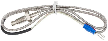
The positive lead, made of Chromel (nickel-chromium alloy), is marked by the red terminal, while the negative lead, composed of Alumel (nickel-aluminum alloy), is indicated by the blue terminal.
Featuring fiberglass insulation, a material renowned for its resistance to high temperatures and harsh conditions, the probe is a suitable choice for a variety of projects.
Terminating in an M6 threaded connection, this design allows the thermocouple to be attached to an object like a heatsink, where it can be screwed in or secured with a nut.
Technical Specifications
Here are the specifications:
| Operating Voltage | 3.0 to 5.5V |
| Interface | High-Speed SPI |
| Current Consumption | 700µA (typ.), 1.5mA (max) |
| Temperature Range | 0 – 1024 °C (of MAX6675)0 – 80 °C (of supplied probe) |
| Accuracy | ±3 °C |
| Resolution | 12-Bit (0.25 °C) |
| Conversion Time | ~170 ms |
For more information about the MAX6675 IC, please refer to the datasheet below.
MAX6675 Module Pinout
Let’s now examine the pinout of the MAX6675 module.
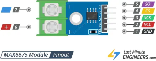
Input Connector
- VCC: serves as the power pin, requiring connection to a power supply within the 3V to 5.5V range.
- GND: is the ground pin.
- SCK: functions as the SPI clock pin.
- CS: is the chip select pin. To read results at SO, pull this pin low and apply a clock signal at SCK. Pulling it low halts any ongoing conversion process, and you can initiate a new conversion by pulling it high.
- SO:, the Serial data Out / MISO pin, transmits 12-bit data from the module to your Arduino. A sequence of all zeros indicates a thermocouple reading of 0°C, while a sequence of all ones signifies a thermocouple reading of +1023.75°C.
Thermocouple Connector
On the opposite side of the module, there is a 2-pin terminal block designed for connecting a Type-K thermocouple probe.
- The “-“ terminal is where you attach the Alumel Lead (blue) of the Type-K thermocouple.
- The “+” terminal is where you attach the Chromel Lead (red) of the Type-K thermocouple.
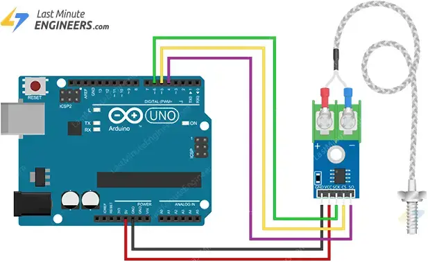
Connecting MAX6675 Thermocouple Module to an Arduino
Let’s establish the connection between the MAX6675 module and the Arduino. The wiring is simple and direct.
Start by linking the VCC pin on the module to the 5V on the Arduino, and connect the GND pin to the ground.
Now, establish connections for the three digital pins to be used for the SPI interface. In this example, we are using pins 4, 5, and 6.
Lastly, affix the thermocouple probe to the module. Connect the red lead (Chromel Lead) of the thermocouple to the ‘+’ terminal of the module, and attach the blue lead (Alumel Lead) to the ‘-‘ terminal.
The table below outlines the pin connections:
| MAX6675 Module Pin | Arduino Pin |
|---|---|
| VCC | 5V |
| GND | Ground |
| SCK | Digital 4 |
| CS | Digital 5 |
| SO | Digital 6 |
| – (Alumel Lead) | – Terminal |
| + (Chromel Lead) | + Terminal |
Parts Required
| Component Name | Buy Now |
| Arduino Uno REV3 | Amazon |
| DC 3-5V MAX6675 Module + K Type Thermocouple Temperature Sensor | Amazon |
| Breadboard | Amazon |
| BOJACK 1000 Pcs 25 Values Resistor Kit 1 Ohm-1M Ohm with 5% 1/4W | Amazon |
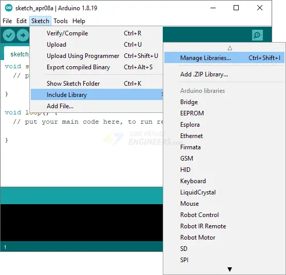
Library Installation
A highly useful library is accessible for interfacing with the MAX6675 module. To integrate it into your Arduino IDE, follow these steps.
Navigate to Sketch > Include Library > Manage Libraries… Allow the Library Manager to download the libraries index and update the list of installed libraries.
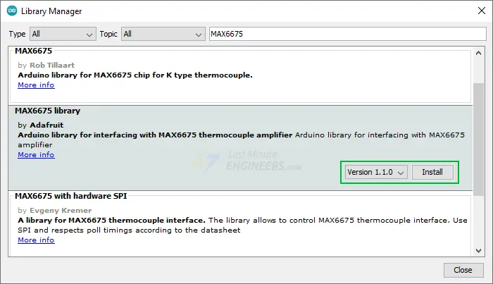
Filter your search by typing ‘MAX6675’. Locate the MAX6675 library developed by Adafruit. Click on the entry and proceed to Install.
Arduino Example Code
Now that all the connections are set up, let’s run a simple sketch to quickly test the MAX6675 module. Upload the sketch to your Arduino, and you’ll observe the ambient temperature printed on the serial interface.
#include "max6675.h"

// Define the Arduino pins, the MAX6675 module is connected to
int SO_PIN = 4;  // Serail Out (SO) pin
int CS_PIN = 5;  // Chip Select (CS) pin
int SCK_PIN = 6; // Clock (SCK) pin

// Create an instance of the MAX6675 class with the specified pins
MAX6675 thermocouple(SCK_PIN, CS_PIN, SO_PIN);

void setup() {
  Serial.begin(9600);
  delay(500);
}

void loop() {
  // Read the current temperature and print it to the serial monitor

  // Read the temperature in Celsius
  Serial.print("Temperature: ");
  Serial.print(thermocouple.readCelsius());
  Serial.print("\xC2\xB0"); // shows degree symbol
  Serial.print("C  |  ");

  // Read the temperature in Fahrenheit
  Serial.print(thermocouple.readFahrenheit());
  Serial.print("\xC2\xB0"); // shows degree symbol
  Serial.println("F");

  delay(1000);
}
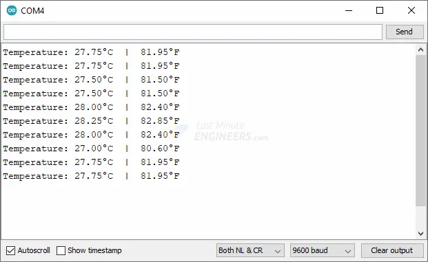
Once the sketch is uploaded, open your serial monitor, setting the baud rate to 9600 bps. Place the thermocouple in contact with the material to be measured, and you should observe the measured temperature appearing on the monitor.
Explanation of the Code:
The sketch starts by including the MAX6675 header file, enabling the Arduino code to communicate with the MAX6675 module.
#include "max6675.h"
In the global section, three integers, SO_PIN, CS_PIN, and SCK_PIN, are declared to specify the Arduino pins connected to the module’s Serial Out (SO) pin, Chip Select (CS) pin, and Clock (SCK) pin.
int SO_PIN = 4;  // Serail Out (SO) pin
int CS_PIN = 5;  // Chip Select (CS) pin
int SCK_PIN = 6; // Clock (SCK) pin
An instance of the MAX6675 class named thermocouple is then created to read from the module. It initializes the thermocouple object with the defined SCK, CS, and SO pins.
MAX6675 thermocouple(SCK_PIN, CS_PIN, SO_PIN);
The setup section of the code initiates serial communication with the computer at a baud rate of 9600.
void setup() {
  Serial.begin(9600);
  delay(500);
}
In the loop(), the temperature is read from the MAX6675 thermocouple and printed to the Serial Monitor using two library functions: thermocouple.readCelsius() for temperature in Celsius and thermocouple.readFahrenheit() for temperature in Fahrenheit.
Serial.print("Temperature: ");
Serial.print(thermocouple.readCelsius());
Serial.print("\xC2\xB0"); // shows degree symbol
Serial.print("C  |  ");

// Read the temperature in Fahrenheit
Serial.print(thermocouple.readFahrenheit());
Serial.print("\xC2\xB0"); // shows degree symbol
Serial.println("F");
The loop continually executes, reading and printing the temperature every second.
Related article
- Step-by-Step Guide: LM35 Temperature Sensor Interfacing with Arduino
- Step-by-Step: Interfacing Multiple DS18B20 Sensors with Arduino
- Arduino DHT11 Sensor Tutorial: How to Interface and Read Data
- Arduino DHT11 and DHT22 Sensor Interface: Step-by-Step Guide


