

Enabling wireless communication between two or more Arduinos unlocks a plethora of opportunities, including remote sensor data monitoring, robot control, home automation, and more.
This tutorial will guide you through the process of establishing wireless communication between two Arduino boards using HC-05 Bluetooth modules, step by step.
Parts Required
| Component Name | Buy Now |
| Arduino Uno REV3 | Amazon |
| HC-05 Bluetooth Serial Pass-through Module | Amazon |
| SG90 9g Micro Servos for RC Robot | Amazon |
| Breadboard Set | Amazon |
Overview
Establishing wireless communication between two Arduino boards involves configuring one HC-05 module as the master and the other as the slave, and then pairing them. This setup, known as master-slave configuration, is the simplest method to create a wireless link between two devices. The master device takes the lead in initiating the connection and scanning for other devices, while the slave device awaits the connection request from the master. Once the connection is established, both the master and slave devices can exchange data in both directions.
To configure the HC-05 modules, they must be connected to a computer and accessed using serial terminal software, such as Arduino IDE Serial Monitor or PuTTY, to send AT commands.
Step 1: Connecting HC-05 Module to the PC
Begin by establishing the connection between the HC-05 module and the PC. You have two options: either utilize a USB-to-TTL converter or employ an Arduino as an intermediary between the PC and the HC-05 module.
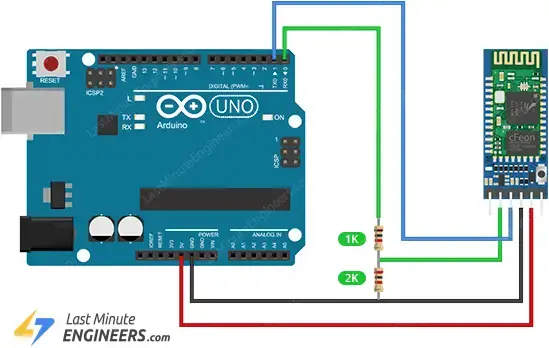
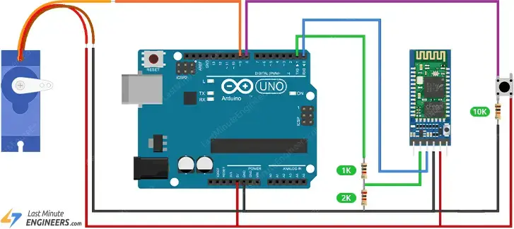
Connecting the HC-05 Module to the Arduino involves simply providing power and connecting the serial Rx and Tx pins. Link the TXD of the HC-05 module to Arduino’s D1, RXD to D0, GND to GND, and VCC to 5V.
It’s important to note that the Rx pin on the HC-05 module is not tolerant to 5V. Therefore, if you’re using a 5V microcontroller like an Arduino UNO, you must step down the Tx signal from the Arduino to 3.3V using a resistor divider. A 1K resistor between HC-05’s Rx and Arduino’s D0, along with a 2K resistor between HC-05’s Rx and GND, will suffice.
In summary, here are the connections:
| HC-05 Module | Arduino | Notes |
| VCC | 5V | – |
| GND | GND | – |
| TX | D1 | – |
| RX | D0 | Use level shifter if using 5V MCU |
The image below shows how to connect the HC-05 module to the Arduino Uno.
Step 2: Configuring the HC-05 Modules
Let’s configure one HC-05 module as a master and the other as a slave.
Slave Configuration
- Press and hold the button on the first HC-05 module while powering it up to enter AT mode. The onboard LED should blink slowly and steadily, indicating readiness to receive AT commands.
- Connect the HC-05 to your PC; it will be recognized as a COM port. In the Arduino IDE, navigate to Tools > Port and select the corresponding COM port.
- Open the Serial Monitor via Tools > Serial Monitor. Ensure the baud rate is set to 38400 and ‘Both NL and CR’ option is selected.
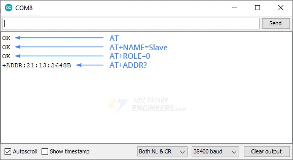
- Type “AT” (without quotes) in the Serial Monitor and press Send; you should receive “OK” as a response.
- Type “AT+NAME=Slave” and press enter to change the module’s name to “Slave”; you should see “OK” as a response.
- Type “AT+ROLE=0” to set the module as a slave; you should receive “OK” as a response. If the module exits AT mode, put it back into AT mode.
- Type “AT+ADDR?” to display the module’s address in hexadecimal format. Note down this address.
- Disconnect the HC-05 module.
Master Configuration
- Repeat steps 1-3 above for the second HC-05 module.
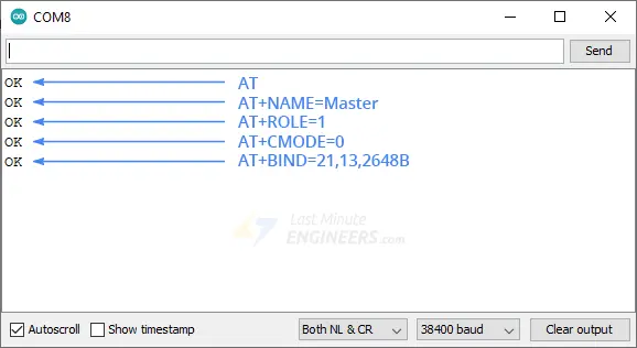
- Type “AT” and press enter; you should see “OK” as a response.
- Type “AT+NAME=Master” to change the module’s name to “Master”; you should receive “OK” as a response.
- Type “AT+ROLE=1” to set the module as a master; you should see “OK” as a response. If the module exits AT mode, put it back into AT mode.
- Type “AT+CMODE=0” to set the connection mode to a fixed address; you should see “OK” as a response.
- Type “AT+BIND=1234,56,abcdef” replacing the address with the one noted from the slave module, using commas instead of colons. This pairs the master module with the slave module; you should see “OK” as a response.
- Disconnect the HC-05 module.
Your HC-05 modules are now configured as master and slave devices. Upon powering up the modules again, the master will establish a connection with the slave, indicated by the LED flash pattern changing to two quick flashes followed by a pause.
Step 3: Hardware Connections
Now, let’s proceed to implement a practical example for this tutorial.
Our example will be straightforward yet illustrative, showcasing how communication between two Arduino boards can be achieved. We’ll employ a potentiometer on the master side to control a servo motor on the slave side, and a push button on the slave side to control an LED on the master side.
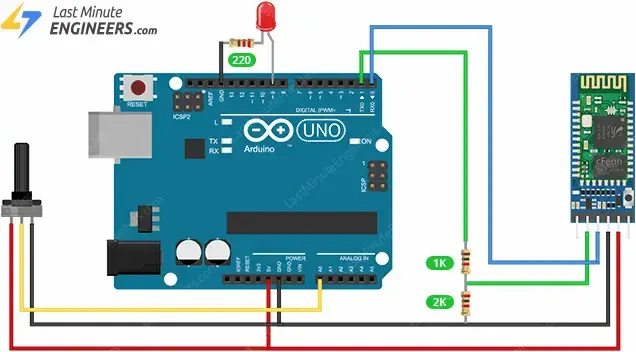
Master Arduino Connections:
- Connect the HC-05 Bluetooth module’s VCC to Arduino’s 5V, GND to GND, TXD to Arduino’s RX (Digital Pin 0), and RXD through a voltage divider to Arduino’s TX (Digital Pin 1).
- Attach one outer pin of the potentiometer to 5V, the opposite outer pin to GND, and its middle pin (wiper) to A0.
- For the LED, connect its positive (longer leg) through a 220Ω resistor to digital pin D9, and its negative (shorter leg) to GND.
Slave Arduino Connections:
- For the HC-05 Bluetooth module on the slave side, connect VCC to Arduino’s 5V, GND to GND, TXD to Arduino’s RX (Digital Pin 0), and RXD through a voltage divider to TX (Digital Pin 1).
- For the servo motor, connect its Power (Red) wire to 5V, Ground (Brown/Black) wire to GND, and Signal (Yellow/Orange) wire to a PWM digital pin, D9.
- Connect one leg of the push button to digital pin D8. Connect the same leg of the button to ground through a 10K pull-down resistor. Connect the other leg of the button to 5V.
With these connections established, the hardware setup for our example is complete.
Step 4: Uploading the Code
We have two Arduino sketches to upload to the Arduino boards.
Master Code
Upload the following sketch to the Master Arduino:
#define ledPin 9

int state = 0;
int potValue = 0;

void setup() {
  pinMode(ledPin, OUTPUT);
  digitalWrite(ledPin, LOW);
  Serial.begin(38400); // Default communication rate of the Bluetooth module
}

void loop() {
 if(Serial.available() > 0){ // Checks whether data is comming from the serial port
    state = Serial.read(); // Reads the data from the serial port
 }
 // Controlling the LED
 if (state == '1') {
  digitalWrite(ledPin, HIGH); // LED ON
  state = 0;
 }
 else if (state == '0') {
  digitalWrite(ledPin, LOW); // LED ON
  state = 0;
 }
 // Reading the potentiometer
 potValue = analogRead(A0);
 int potValueMapped = map(potValue, 0, 1023, 0, 255);
 Serial.write(potValueMapped); // Sends potValue to servo motor
 delay(10);
}
Slave Code
Upload the following sketch to the Slave Arduino:
#include <Servo.h>
#define button 8

Servo myServo;
int state = 20;
int buttonState = 0;

void setup() {
  pinMode(button, INPUT);
  myServo.attach(9);
  Serial.begin(38400); // Default communication rate of the Bluetooth module
}

void loop() {
 if(Serial.available() > 0){ // Checks whether data is comming from the serial port
    state = Serial.read(); // Reads the data from the serial port
 }
 // Controlling the servo motor
 myServo.write(state);
 delay(10);

 // Reading the button
 buttonState = digitalRead(button);
 if (buttonState == HIGH) {
   Serial.write('1'); // Sends '1' to the master to turn on LED
 }
 else {
   Serial.write('0');
 }
}
Code Explanation:
In the master Arduino sketch, digital pin 9 is configured to control an LED, and the potentiometer is linked to analog pin A0. Upon initialization, the code monitors incoming serial data, representing the button state from the slave. Depending on the received value (‘1’ or ‘0’), the LED is activated or deactivated, correspondingly. Concurrently, the potentiometer value is read, mapped from its range (0-1023) to a byte value (0-255), and transmitted via Bluetooth to regulate the servo motor on the slave side.
For the slave Arduino, the code begins by including the Servo library and assigning digital pin 8 for button input. A servo object is instantiated and connected to digital pin 9. Within the loop, the code continuously checks for incoming serial data. This data directly influences the angle of the servo motor. Simultaneously, the state of the button is monitored. If pressed, a ‘1’ is transmitted to the master to activate the LED; otherwise, a ‘0’ is sent.
Step 5: Testing it Out
Now, adjust the potentiometer on the master Arduino. As you change its position, the servo motor on the slave Arduino should respond accordingly, adjusting its angle based on the potentiometer rotation.
Next, press the button on the slave Arduino. Upon pressing, the LED on the master Arduino should light up. Releasing the button should turn off the LED.
Related article
- Mastering AT Commands for HC-05 Configuration
- MAX4466 Microphone Module: Arduino Interface Guide
- Step-by-Step Guide: HC-SR501 PIR Sensor Working Principles and Arduino Integration
- Understanding the Operation of HC-SR04 Ultrasonic Sensor and Connecting it to Arduino
- DIY Project: Arduino Interface for TFMini-S LiDAR Sensor


