

Learn how to use the ESP8266 NodeMCU board to publish and subscribe to MQTT topics. In this tutorial, we will use the Node-RED dashboard to control the ESP8266 outputs and display its sensor data. The Node-RED software runs on a Raspberry Pi, with communication between the ESP8266 and Node-RED handled via the MQTT protocol. We will program the ESP8266 using the Arduino IDE.
Project Overview
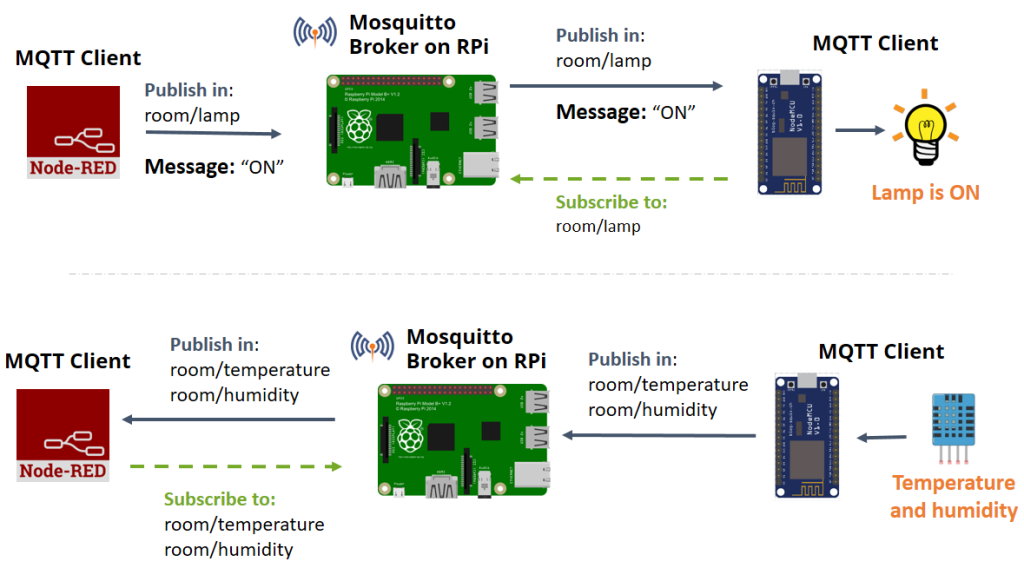
The figure below provides an overview of this tutorial’s tasks.
Parts Required
Node-RED and Node-RED Dashboard
To complete this tutorial, you need Node-RED and the Node-RED Dashboard installed on your Raspberry Pi. Refer to the following guides to install and set up Node-RED and its dashboard:
MQTT Protocol
We will set up communication between a Raspberry Pi running Node-RED and an ESP8266 using MQTT.
MQTT stands for MQ Telemetry Transport. It is a lightweight publish-and-subscribe system that allows clients to publish and receive messages. Designed for constrained devices and low bandwidth, MQTT is ideal for Internet of Things applications.
For more information about MQTT, watch the video below.
Installing Mosquitto Broker
The MQTT broker’s role is to receive all messages, filter them, determine who is interested, and publish the messages to all subscribed clients.
There are various brokers available, but in this tutorial, we will use the Mosquitto Broker.

You can install the Mosquitto MQTT broker on a Raspberry Pi, your computer, or in the cloud. Follow one of the tutorials below to install the Mosquitto broker:
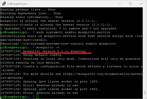
To verify if the Mosquitto broker is successfully installed, run the following command:
pi@raspberry:~ $ mosquitto -v
This command returns the Mosquitto version currently running on your Raspberry Pi. It should be version 2.0.11 or above.
Establishing MQTT Communication with Node-RED
In this section, we’ll set up MQTT communication with Node-RED using MQTT nodes.
Dashboard Layout
First, create the dashboard layout. We will include a button to control an ESP8266 output, a chart, and a gauge to display temperature and humidity readings from a DHT11 sensor.
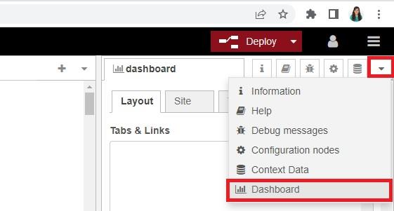
In the top right corner, click the arrow icon, then select Dashboard.
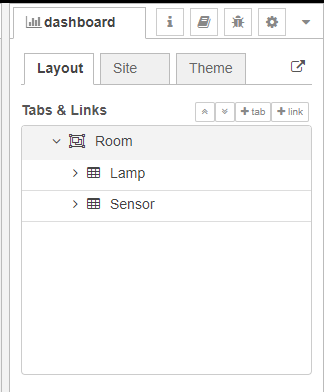
In the Layout tab, create a tab called Room. Within this tab, create two groups: Lamp and Sensor, as shown in the figure below.
Creating the Flow
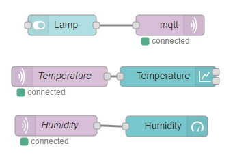
From the dashboard section on the left sidebar, drag a switch, a chart, and a gauge node into the flow. Then, drag two MQTT in nodes and one MQTT out node into the flow (these are found in the network section), as illustrated below.
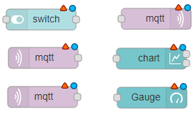
- Switch: Controls the ESP8266 output.
- MQTT Output Node: Publishes a message to the ESP8266 based on the switch state.
- MQTT Input Nodes (2): Subscribed to temperature and humidity topics to receive sensor data from the ESP.
- Chart: Displays the temperature sensor readings.
- Gauge: Displays the humidity sensor readings.
Node-RED must be connected to the MQTT broker. To do this, double-click the MQTT output node. A new window will open, as shown below.
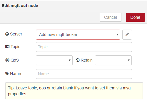
- Click Add new mqtt-broker.
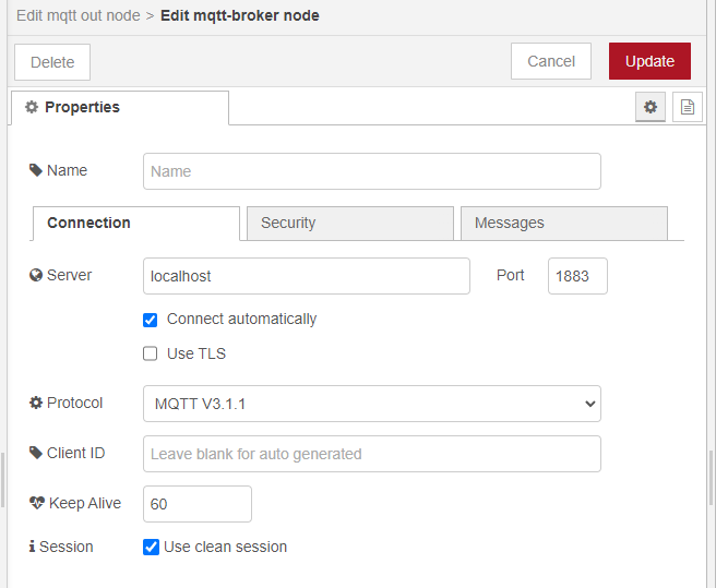
- Enter localhost in the Server field. The default settings are usually fine.
If Node-RED is not running on the same machine as your MQTT broker (Raspberry Pi), enter the MQTT broker’s IP address instead of localhost.
- Click the Security tab and enter your MQTT broker username and password if needed.
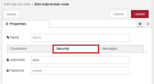
- Click Update and then Add. The MQTT output node will connect to your broker after you deploy the Node-RED flow.
Edit the other nodes’ properties according to the following instructions.
Switch Node
The switch sends an on string message when on, and an off string message when off. This node will publish on the room/lamp topic. The ESP8266 will subscribe to this topic to receive messages. Edit the node properties as shown below.

MQTT Output Node
This node connects to the Mosquitto MQTT broker and will publish in the room/lamp topic. Fill in the details as shown below, including the topic, QoS value, and whether to retain messages.
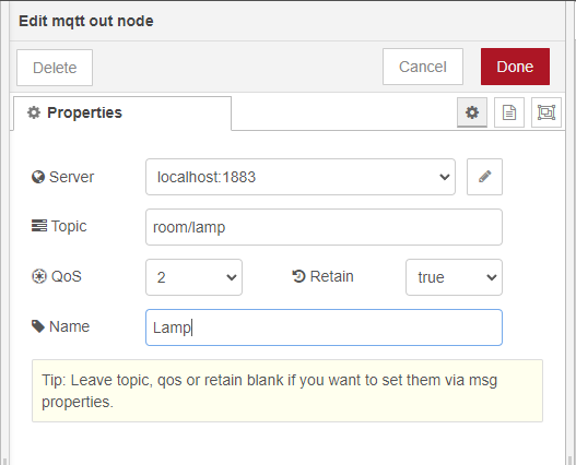
A retained message is a standard MQTT message with the retained flag set to true. The broker stores the last retained message and the corresponding QoS for a topic. Each client that subscribes to a topic matching the retained message receives it immediately after subscribing. The broker stores only one retained message per topic.
Why are retained messages useful?
Retained messages provide newly-subscribed clients with an immediate status update. This is particularly useful for device status updates. For instance, if GPIO 2 is HIGH and the ESP32 resets, it won’t know the last state of GPIO 2. However, if the state is a retained message, it will receive it right after subscribing and can update the state of GPIO 2 immediately.
MQTT Input Node
This node subscribes to the room/temperature topic to receive temperature data from the ESP8266. The ESP8266 will publish temperature readings to this topic.
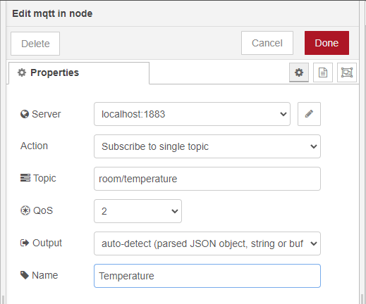
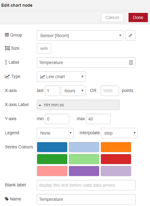
Chart Node
The chart displays readings received on the room/temperature topic.
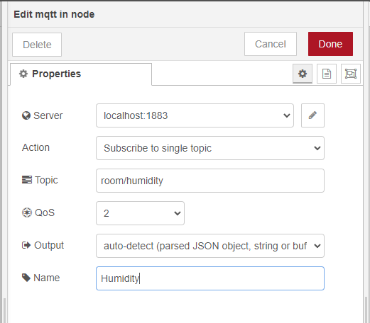
MQTT Input Node
This node subscribes to the room/humidity topic to receive humidity data from the ESP8266. The ESP8266 will publish humidity readings to this topic.
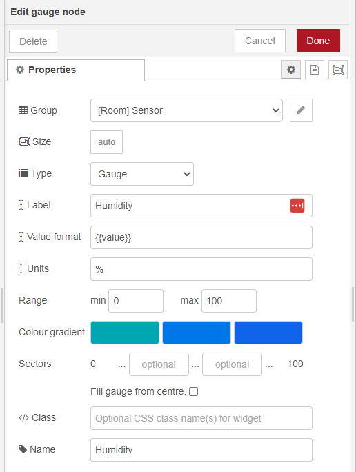
Gauge Node
The gauge displays readings received on the room/humidity topic. Edit the gauge properties as needed and adjust the color gradient to your preference.
Wire your nodes as shown in the figure below.
Your Node-RED application is now ready. Click the Deploy button in the top right corner.

To view your dashboard, go to http://your-pi-ip-address:1880/ui.
Next, follow the subsequent sections to prepare your ESP8266.
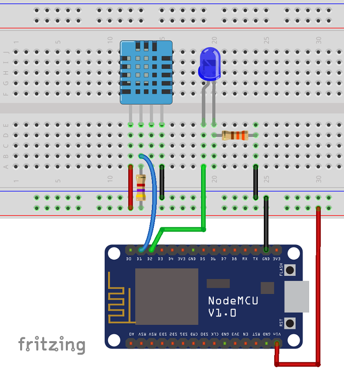
Schematics
Below are the schematics for the circuit used in this project.
Preparing Your Arduino IDE
We’ll program the ESP8266 using the Arduino IDE. To upload code to your ESP8266, you’ll need to install the ESP8266 add-on for the Arduino IDE and two additional libraries.
Installing the PubSubClient Library
The PubSubClient library allows your ESP8266 to communicate with Node-RED using MQTT.
- Download the PubSubClient library. This will save a
.zipfile in your Downloads folder. - In the Arduino IDE, go to Sketch > Include Library > Add .ZIP Library and select the
.zipfile you downloaded. - Restart your Arduino IDE.
The library includes several examples, which you can find under File > Examples > PubSubClient.
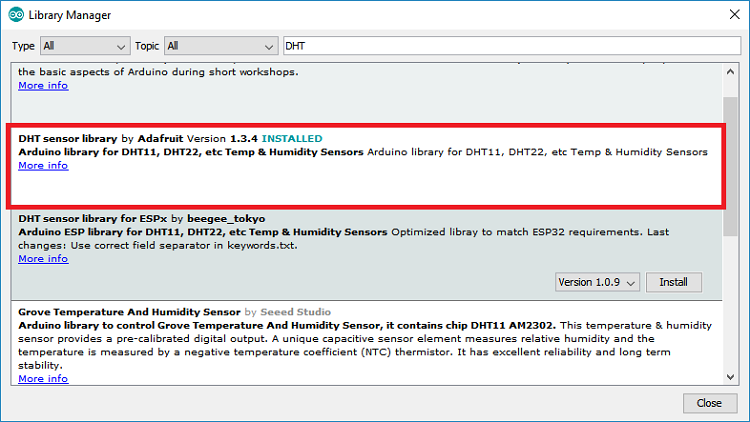
Installing the DHT Sensor Library
To read data from the DHT sensor, we’ll use the DHT library from Adafruit. This library requires the Adafruit Unified Sensor library.
- Open your Arduino IDE and go to Sketch > Include Library > Manage Libraries. This will open the Library Manager.
- Search for “DHT” in the search box and install the DHT library from Adafruit.
- After installing the DHT library, search for “Adafruit Unified Sensor” in the search box. Scroll down to find and install the library.
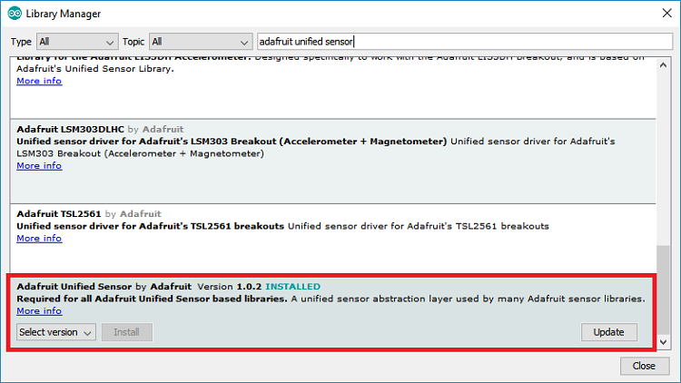
- Restart your Arduino IDE after installing the libraries.
Selecting the Right Board in Arduino IDE
Ensure you select the correct board in the Arduino IDE:
- Go to Tools > Board and select the ESP8266 board you are using.
- Select the appropriate COM port under Tools > Port.
By following these steps, you’ll be ready to program your ESP8266 with the Arduino IDE.
Uploading code
Now, upload the following code to your ESP8266. This code will publish temperature and humidity data from the DHT11 sensor to the room/temperature and room/humidity topics using MQTT. The ESP8266 will also subscribe to the room/lamp topic to control a lamp based on messages from the Node-RED application.
The code is commented to guide you on necessary changes. You need to enter your network credentials (SSID and password) and broker details (Raspberry Pi IP address, MQTT broker username, and password).
This code works with other DHT sensors as well; just uncomment the relevant lines for your sensor type.
#include <ESP8266WiFi.h>
#include <PubSubClient.h>
#include "DHT.h"

// Uncomment one of the lines bellow for whatever DHT sensor type you're using!
#define DHTTYPE DHT11   // DHT 11
//#define DHTTYPE DHT21   // DHT 21 (AM2301)
//#define DHTTYPE DHT22   // DHT 22  (AM2302), AM2321

// Change the credentials below, so your ESP8266 connects to your router
const char* ssid = "REPLACE_WITH_YOUR_SSID";
const char* password = "REPLACE_WITH_YOUR_PASSWORD";

// MQTT broker credentials (set to NULL if not required)
const char* MQTT_username = "REPLACE_WITH_MQTT_USERNAME";
const char* MQTT_password = "REPLACE_WITH_MQTT_PASSWORD";

// Change the variable to your Raspberry Pi IP address, so it connects to your MQTT broker
const char* mqtt_server = "YOUR_BROKER_IP_ADDRESS";
//For example
//const char* mqtt_server = "192.168.1.106";

// Initializes the espClient. You should change the espClient name if you have multiple ESPs running in your home automation system
WiFiClient espClient;
PubSubClient client(espClient);

// DHT Sensor - GPIO 5 = D1 on ESP-12E NodeMCU board
const int DHTPin = 5;

// Lamp - LED - GPIO 4 = D2 on ESP-12E NodeMCU board
const int lamp = 4;

// Initialize DHT sensor.
DHT dht(DHTPin, DHTTYPE);

// Timers auxiliar variables
long now = millis();
long lastMeasure = 0;

// This functions connects your ESP8266 to your router
void setup_wifi() {
  delay(10);
  // We start by connecting to a WiFi network
  Serial.println();
  Serial.print("Connecting to ");
  Serial.println(ssid);
  WiFi.begin(ssid, password);
  while (WiFi.status() != WL_CONNECTED) {
    delay(500);
    Serial.print(".");
  }
  Serial.println("");
  Serial.print("WiFi connected - ESP IP address: ");
  Serial.println(WiFi.localIP());
}

// This function is executed when some device publishes a message to a topic that your ESP8266 is subscribed to
// Change the function below to add logic to your program, so when a device publishes a message to a topic that
// your ESP8266 is subscribed you can actually do something
void callback(String topic, byte* message, unsigned int length) {
  Serial.print("Message arrived on topic: ");
  Serial.print(topic);
  Serial.print(". Message: ");
  String messageTemp;

  for (int i = 0; i < length; i++) {
    Serial.print((char)message[i]);
    messageTemp += (char)message[i];
  }
  Serial.println();

  // Feel free to add more if statements to control more GPIOs with MQTT

  // If a message is received on the topic room/lamp, you check if the message is either on or off. Turns the lamp GPIO according to the message
  if(topic=="room/lamp"){
      Serial.print("Changing Room lamp to ");
      if(messageTemp == "on"){
        digitalWrite(lamp, HIGH);
        Serial.print("On");
      }
      else if(messageTemp == "off"){
        digitalWrite(lamp, LOW);
        Serial.print("Off");
      }
  }
  Serial.println();
}

// This functions reconnects your ESP8266 to your MQTT broker
// Change the function below if you want to subscribe to more topics with your ESP8266
void reconnect() {
  // Loop until we're reconnected
  while (!client.connected()) {
    Serial.print("Attempting MQTT connection...");
    // Attempt to connect
    /*
     YOU MIGHT NEED TO CHANGE THIS LINE, IF YOU'RE HAVING PROBLEMS WITH MQTT MULTIPLE CONNECTIONS
     To change the ESP device ID, you will have to give a new name to the ESP8266.
     Here's how it looks:
       if (client.connect("ESP8266Client")) {
     You can do it like this:
       if (client.connect("ESP1_Office")) {
     Then, for the other ESP:
       if (client.connect("ESP2_Garage")) {
      That should solve your MQTT multiple connections problem
    */
    if (client.connect("ESP8266Client", MQTT_username, MQTT_password)) {
      Serial.println("connected");
      // Subscribe or resubscribe to a topic
      // You can subscribe to more topics (to control more LEDs in this example)
      client.subscribe("room/lamp");
    } else {
      Serial.print("failed, rc=");
      Serial.print(client.state());
      Serial.println(" try again in 5 seconds");
      // Wait 5 seconds before retrying
      delay(5000);
    }
  }
}

// The setup function sets your ESP GPIOs to Outputs, starts the serial communication at a baud rate of 115200
// Sets your mqtt broker and sets the callback function
// The callback function is what receives messages and actually controls the LEDs
void setup() {
  pinMode(lamp, OUTPUT);

  dht.begin();

  Serial.begin(115200);
  setup_wifi();
  client.setServer(mqtt_server, 1883);
  client.setCallback(callback);

}

// For this project, you don't need to change anything in the loop function. Basically it ensures that you ESP is connected to your broker
void loop() {

  if (!client.connected()) {
    reconnect();
  }
  if(!client.loop())
    client.connect("ESP8266Client", MQTT_username, MQTT_password);

  now = millis();
  // Publishes new temperature and humidity every 30 seconds
  if (now - lastMeasure > 30000) {
    lastMeasure = now;
    // Sensor readings may also be up to 2 seconds 'old' (its a very slow sensor)
    float humidity = dht.readHumidity();
    // Read temperature as Celsius (the default)
    float temperatureC = dht.readTemperature();
    // Read temperature as Fahrenheit (isFahrenheit = true)
    float temperatureF = dht.readTemperature(true);

    // Check if any reads failed and exit early (to try again).
    if (isnan(humidity) || isnan(temperatureC) || isnan(temperatureF)) {
      Serial.println("Failed to read from DHT sensor!");
      return;
    }

    // Publishes Temperature and Humidity values
    client.publish("room/temperature", String(temperatureC).c_str());
    client.publish("room/humidity", String(humidity).c_str());
    //Uncomment to publish temperature in F degrees
    //client.publish("room/temperature", String(temperatureF).c_str());

    Serial.print("Humidity: ");
    Serial.print(humidity);
    Serial.println(" %");
    Serial.print("Temperature: ");
    Serial.print(temperatureC);
    Serial.println(" ºC");
    Serial.print(temperatureF);
    Serial.println(" ºF");
  }
}
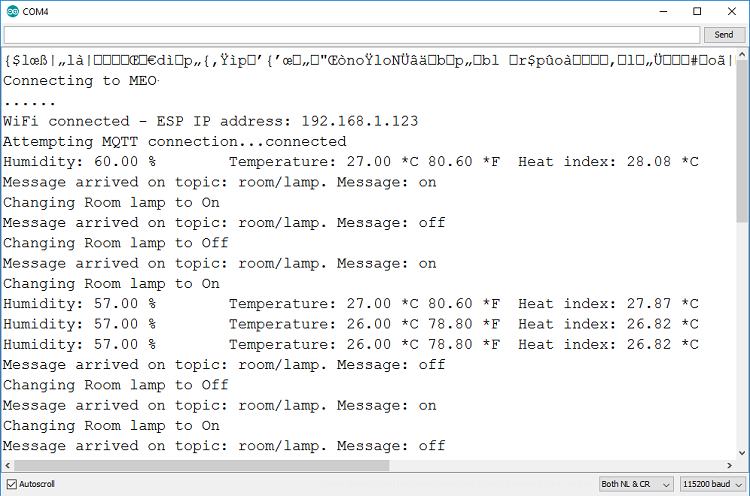
After uploading the code, open the Arduino IDE serial monitor at a baud rate of 115200 to see the real-time status. This helps you verify if the ESP8266 is connected to your router and the Mosquitto broker, and to observe the messages it receives and publishes.
Demonstration
Congratulations! Your project is now complete.
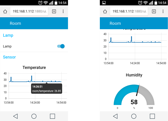
Visit http://your-pi-ip-address/ui to control the ESP8266 with the Node-RED application. You can access your application from any browser on the same network as your Raspberry Pi.
The application should resemble the figure below.
Wrapping Up
In this tutorial, we’ve covered the basics of controlling lights and monitoring sensors on the ESP8266 using Node-RED and MQTT. You can use these steps to develop more advanced projects.
- Firebase Authentication with ESP32/ESP8266: Email and Password Guide
- Firebase Data Logging: ESP8266 NodeMCU Sensor Integration
- Beginner’s Guide to ESP8266 NodeMCU and Firebase (Realtime Database)


