

A few years ago, if someone asked how much a WiFi-enabled digital camera would cost, $10 would have been an unexpected answer. However, that’s no longer true.
The ESP32-CAM, which debuted in early 2019, revolutionized this space. Remarkably, for under $10, you get an ESP32 with camera and SD card support.
These modules are quite handy. Whether for motion detection in a Halloween project, facial recognition, license plate decoding, or simply as a security camera, they’re invaluable in a DIY toolkit.
ESP32-CAM Hardware Overview
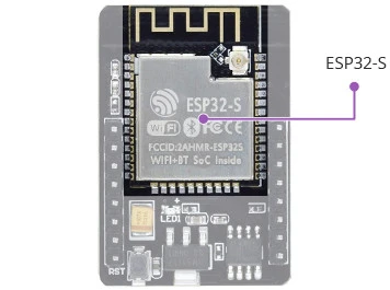
At the core of the ESP32-CAM is the ESP32-S System-on-Chip (SoC) from Ai-Thinker. As an SoC, the ESP32-S includes a microprocessor, RAM, storage, and peripherals all on one chip. While the chip itself is impressive, the ESP32-CAM development board enhances its capabilities even further. Let’s break down its components:
The ESP32-S Processor
The ESP32-CAM features the ESP32-S module from Ai-Thinker, akin to Espressif’s ESP-WROOM-32 module. It has a Tensilica Xtensa® LX6 microprocessor with two 32-bit cores running at 240 MHz, making it suitable for tasks like video processing, facial recognition, and AI.
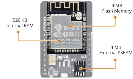
The Memory
For complex tasks, memory is crucial. The ESP32-S includes 520 KB of internal RAM, supplemented by 4 MB of external PSRAM (Pseudo-Static RAM), providing ample capacity for audio or graphics processing. Additionally, the ESP32-S has 4 MB of on-chip flash memory for storage.
The Camera
What sets the ESP32-CAM apart is its OV2640 camera sensor, ideal for video projects like doorbells or nanny cams. This 2-megapixel camera can capture images at 1600×1200 pixels, sufficient for many surveillance applications. The ESP32-CAM supports a variety of camera sensors listed on GitHub.
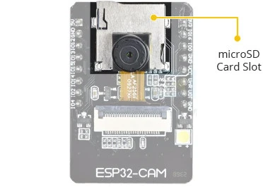
The Storage
The ESP32-CAM includes a microSD card slot, allowing for extensive data storage, making it ideal for data logging or image capture.

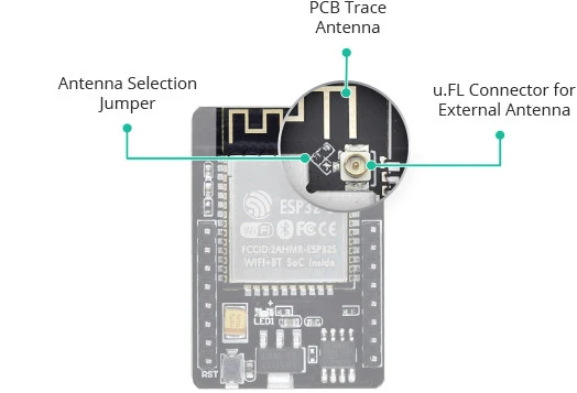
The Antenna
It features a PCB trace antenna and a u.FL connector for an external antenna, with a jumper allowing you to switch between them. For details, see instructions on connecting an external antenna to the ESP32-CAM.
LEDs
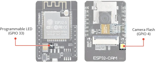
The ESP32-CAM has a white LED for use as a flash or general illumination, and a red LED on the back as a status indicator, connected to GPIO33 and user-programmable.
Technical Specifications
Processors:
- CPU: Xtensa dual-core 32-bit LX6 microprocessor, 240 MHz, up to 600 DMIPS
- Ultra low power (ULP) co-processor
Memory:
- 520 KB SRAM
- 4 MB External PSRAM
- 4 MB internal flash memory
Wireless Connectivity:
- Wi-Fi: 802.11 b/g/n
- Bluetooth: v4.2 BR/EDR and BLE (shares the radio with Wi-Fi)
Camera:
- 2 Megapixel OV2640 sensor
- Resolution: UXGA 1622×1200
- Output formats: YUV422, YUV420, RGB565, RGB555, 8-bit compressed data
- Image transfer rate: 15 to 60 fps
- Built-in flash LED
- Supports various camera sensors
Security:
- IEEE 802.11 standard security features, including WFA, WPA/WPA2, WAPI
- Secure boot
- Flash encryption
- 1024-bit OTP, up to 768-bit for customers
- Cryptographic hardware acceleration: AES, SHA-2, RSA, ECC, RNG
Power Management:
- Internal low-dropout regulator
- Individual power domain for RTC
- 5μA deep sleep current
- Wake up from GPIO interrupt, timer, ADC measurements, capacitive touch sensor interrupt
Schematic and Datasheets
For more details on the ESP32-CAM, please refer to the official documentation and datasheets.
ESP32-CAM Power Consumption
The power consumption of the ESP32-CAM varies depending on what you’re using it for.
It ranges from 80 mAh when not streaming video to around 100~160 mAh when streaming video; with the flash on, it can reach 270 mAh.
| Operation mode | Power Consumption |
| Stand by | 80 mAh |
| In streaming | 100~160 mAh |
| In streaming with flash | 270 mAh |
ESP32-CAM Pinout
The ESP32-CAM has a total of 16 pins, conveniently grouped by similar functionality. Here’s a breakdown of the pinout:
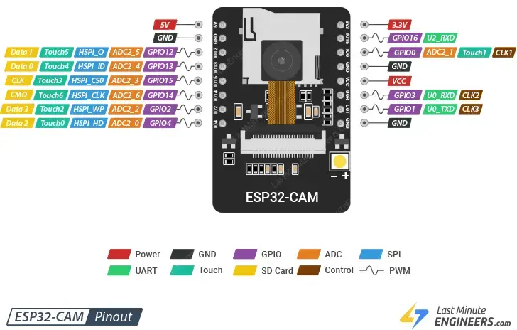
Power Pins
- 5V and 3V3: The ESP32-CAM can be powered through either the 3.3V or 5V pins. Due to reported issues with 3.3V power, it is recommended to use the 5V pin for powering the device. The VCC pin typically outputs 3.3V from the onboard voltage regulator but can be configured to output 5V by using the Zero-ohm link near the VCC pin.
- GND: This is the ground pin.
GPIO Pins
- The ESP32-S chip features 32 GPIO pins in total. However, many are used internally for the camera and PSRAM, leaving 10 GPIO pins available on the ESP32-CAM. These pins can be assigned various peripheral functions, including UART, SPI, ADC, and touch.
UART Pins
- The ESP32-S chip has two UART interfaces: UART0 and UART2. Only the RX pin (GPIO 16) of UART2 is available, making UART0 (GPIO 1 and GPIO 3) the primary UART interface on the ESP32-CAM. These pins are used for both flashing the device and connecting to UART peripherals like GPS, fingerprint sensors, and distance sensors.
MicroSD Card Pins
- These pins are designated for interfacing with a microSD card. If not using a microSD card, these pins can function as general input/output pins.
ADC Pins
- Only ADC2 pins are available on the ESP32-CAM. However, these pins are utilized by the WiFi driver internally and cannot be used when WiFi is enabled.
Touch Pins
- The ESP32-CAM includes 7 capacitive touch-sensing GPIOs. These detect changes in capacitance when a capacitive load, such as a human finger, is near the GPIO.
SPI Pins
- The ESP32-CAM has one SPI interface (VSPI) that supports both slave and master modes.
PWM Pins
- The ESP32-CAM has 10 PWM channels, controlled by a PWM controller, available on all GPIO pins. These PWM outputs are suitable for driving digital motors and LEDs.
For detailed information, refer to our comprehensive ESP32-CAM pinout reference guide, which explains which GPIO pins are safe to use and which should be handled with caution.
Programming the ESP32-CAM
Programming the ESP32-CAM can be a bit challenging since it doesn’t come with a built-in USB port. This means you need additional hardware to upload programs from the Arduino IDE. While not overly complicated, it can be inconvenient.
To program the ESP32-CAM, you need either a USB-to-serial adapter (such as an FTDI adapter) or an ESP32-CAM-MB programmer adapter.
Using the FTDI Adapter
If you choose to use an FTDI adapter, follow these steps to connect it to the ESP32-CAM module:
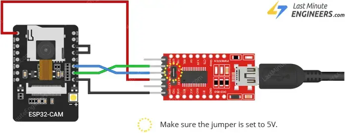
- Ensure your FTDI adapter has a jumper to switch between 3.3V and 5V. Set the jumper to 5V since the ESP32-CAM is powered by 5V.
- Connect the GPIO 0 pin to Ground. This connection is required only during programming. After uploading the program, disconnect this connection.
Remember, you’ll need to connect GPIO 0 to Ground every time you upload a new sketch.
Using the ESP32-CAM-MB Adapter (Recommended)
Using the FTDI adapter can be cumbersome, so many vendors now offer the ESP32-CAM with a small add-on board called the ESP32-CAM-MB.
With the ESP32-CAM-MB adapter, simply stack the ESP32-CAM onto the daughterboard, connect a micro USB cable, and click the Upload button in your IDE. It’s straightforward and user-friendly.
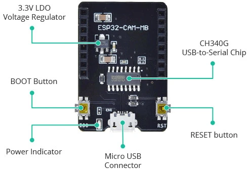
The ESP32-CAM-MB features a CH340G USB-to-Serial converter, which handles data transfer between your computer and the ESP32-CAM. Additionally, it includes a RESET button, a BOOT button, a power indicator LED, and a voltage regulator to ensure the ESP32-CAM receives adequate power.
Parts Required
| Component Name | Buy Now |
| ESP32 Cam WiFi Bluetooth Development Board | Amazon |
Setting Up the Arduino IDE
Installing the ESP32 Board
To use the ESP32-CAM with the Arduino IDE, you first need to install the ESP32 board package (also known as the ESP32 Arduino Core) via the Arduino Board Manager.
If you haven’t done this yet, follow the tutorial to install the ESP32 board package.
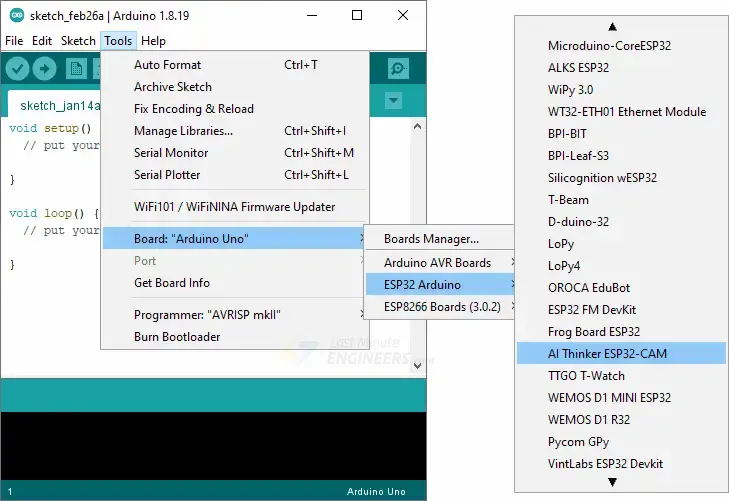
Selecting the Board and Port
Once the ESP32 Arduino Core is installed, restart the Arduino IDE. Then go to Tools > Board > ESP32 Arduino and select AI-Thinker ESP32-CAM.
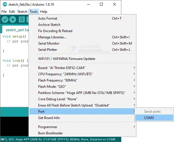
Connect the ESP32-CAM to your computer using a USB cable. Then, go to Tools > Port and select the COM port to which the ESP32-CAM is connected.
Your Arduino IDE is now set up for the ESP32-CAM!
ESP32-CAM Example 1 : Blink
Now that your setup is complete, let’s test your first program with the ESP32-CAM! Open the Arduino IDE. If you disconnected your board, plug it back in.
Let’s upload the most basic sketch: Blink! This sketch uses the on-board camera flash LED, connected to GPIO 4.
int flashPin = 4;

void setup() {
    pinMode(flashPin, OUTPUT);
}

void loop() {
    digitalWrite(flashPin, HIGH);
    delay(1000);
    digitalWrite(flashPin, LOW);
    delay(1000);
}
Press the upload button. If you’re using the FTDI adapter, disconnect GPIO 0 from GND after uploading the code. You might need to press the Reset button on your ESP32-CAM to run the sketch.
If everything is set up correctly, the on-board flash LED on your ESP32-CAM should now be blinking!
Congratulations! You’ve successfully programmed your first ESP32-CAM.
More ESP32-CAM Examples
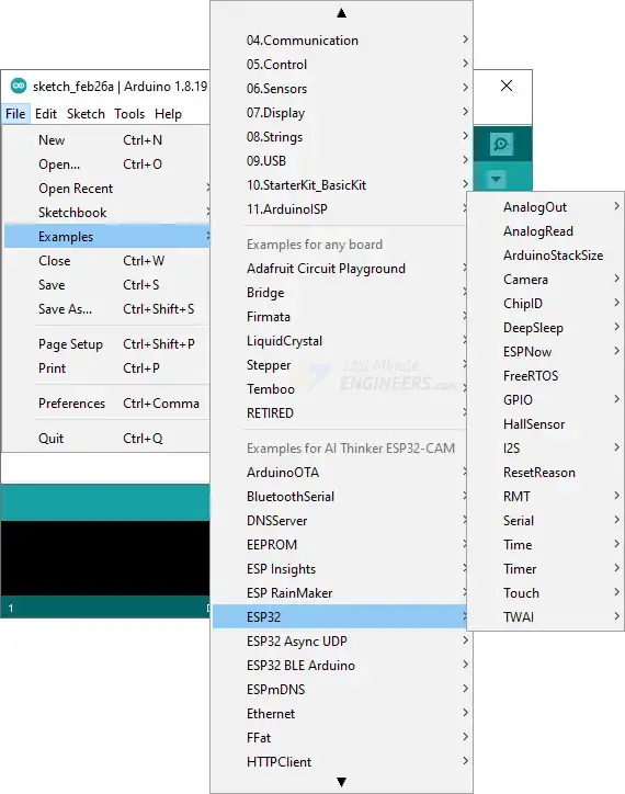
The ESP32 Arduino core provides numerous example sketches that showcase various features, from network scanning to building web servers. To access these examples, go to File > Examples > ESP32 in the Arduino IDE.
You will find a range of example sketches. Choose any to load it into your IDE and start experimenting.
ESP32-CAM Example 2: Live Video Streaming Server
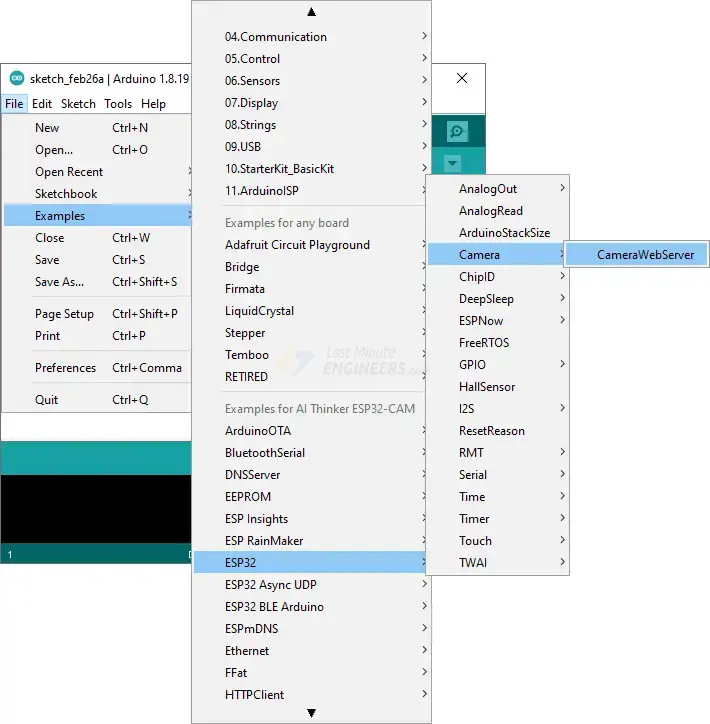
Let’s try the CameraWebServer sketch, which turns the ESP32-CAM into a webcam with features like face detection and extensive customization options. This example demonstrates the ESP32-CAM’s impressive capabilities.
Find this example under File > Examples > ESP32 > Camera > CameraWebServer.
Configuring the CameraWebServer Sketch
To get this sketch working with your ESP32-CAM, you need to make a few adjustments:
Select the Camera Model: Since we’re using the AI-THINKER model, uncomment this line and comment out the others.
// ===================
// Select camera model
// ===================
//#define CAMERA_MODEL_WROVER_KIT // Has PSRAM
//#define CAMERA_MODEL_ESP_EYE // Has PSRAM
//#define CAMERA_MODEL_ESP32S3_EYE // Has PSRAM
//#define CAMERA_MODEL_M5STACK_PSRAM // Has PSRAM
//#define CAMERA_MODEL_M5STACK_V2_PSRAM // M5Camera version B Has PSRAM
//#define CAMERA_MODEL_M5STACK_WIDE // Has PSRAM
//#define CAMERA_MODEL_M5STACK_ESP32CAM // No PSRAM
//#define CAMERA_MODEL_M5STACK_UNITCAM // No PSRAM
#define CAMERA_MODEL_AI_THINKER // Has PSRAM
//#define CAMERA_MODEL_TTGO_T_JOURNAL // No PSRAM
// ** Espressif Internal Boards **
//#define CAMERA_MODEL_ESP32_CAM_BOARD
//#define CAMERA_MODEL_ESP32S2_CAM_BOARD
//#define CAMERA_MODEL_ESP32S3_CAM_LCD
Network Credentials: Enter your Wi-Fi network’s SSID and password in the following lines:
const char* ssid = "REPLACE_WITH_YOUR_SSID";
const char* password = "REPLACE_WITH_YOUR_PASSWORD";
Your code is now ready to be uploaded to the ESP32-CAM.
Accessing the Video Streaming Server
After uploading the sketch, open the serial monitor at a baud rate of 115200 and press the Reset button on the ESP32-CAM. The serial monitor will display the IP address assigned to the ESP32-CAM.
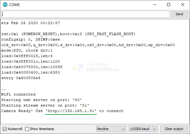
Open a web browser and enter the IP address displayed in the serial monitor. Ensure your web browser is connected to the same network as the ESP32-CAM.
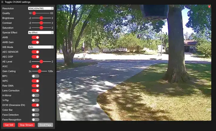
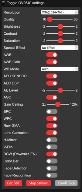
The ESP32-CAM will display a web page. Click the Start Stream button to begin video streaming. You can adjust various camera settings in the left pane, such as resolution, frame rate, brightness, contrast, and saturation. To take a picture, click the Get Still button. Note that images are downloaded to your computer, not saved on the microSD card.
Connecting an External Antenna to ESP32-CAM
The ESP32-CAM includes an onboard PCB trace antenna and a u.FL connector for an external antenna. You can switch between them using an Antenna Selection jumper (a zero-ohm resistor).
The PCB antenna is suitable for initial experiments and works well if you’re close to your router (AI-Thinker claims the PCB antenna has a gain of 2.1dBi).
If you’re far from your router and experience slow streaming or connectivity issues, use a 2.4GHz external antenna with an IPX connector. To enable the u.FL connector, change the antenna jumper settings.

Locate the trio of solder pads next to the u.FL connector and between the onboard antenna and the ESP32-S’s metal case. A zero-ohm resistor connects the top two pads. Remove this resistor and place it between the bottom two pads to switch to the external antenna.
Related article
- ESP32 Upload Error: Fix “Failed to Connect, Timed Out” Issue Fast
- How to Assign a Fixed IP Address to Your ESP32 Device
- Learn How to Set Up mDNS on ESP32 in Minutes
- ESP32 vs. ESP8266: Which Microcontroller Fits Your Requirements?
- ESP32-CAM Pin Assignment Overview


