
The ESP32-CAM is undeniably a powerful device, featuring an integrated camera and WiFi capability. However, it has a limited number of I/O pins, with some being shared with the SD card, rendering them unusable when the card is inserted. This can complicate project design.
Be sure to carefully review the pinout details.
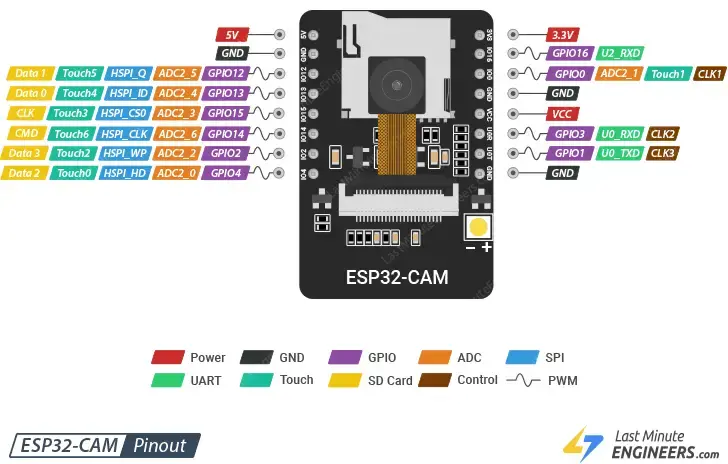
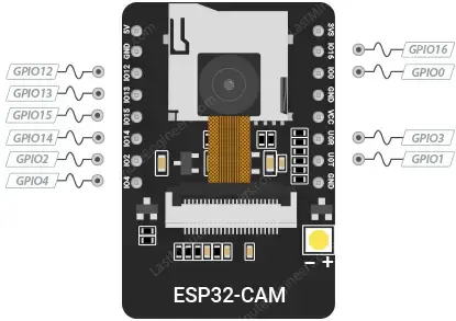
The pinout reference provided is specifically for the widely-used AI-Thinker ESP32-CAM board.
ESP32-CAM Pinout
The ESP32-CAM has a total of 16 pins, conveniently grouped by functionality. Here’s the pinout overview:
Parts Required
| Component Name | Buy Now |
| ESP32 Cam WiFi Bluetooth Development Board | Amazon |
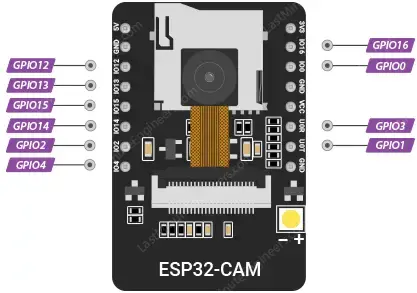
GPIO Pins
The ESP32-S chip has 32 GPIO pins, but due to internal usage for the camera and PSRAM, only 10 GPIO pins are available on the ESP32-CAM. These pins can be programmed for various functions like UART, SPI, ADC, and Touch by setting the appropriate registers.
Safe GPIO Usage on ESP32-CAM
While the ESP32-CAM has 10 GPIO pins with diverse functions, not all of them are suitable for every project. The table below indicates which pins are safe to use and which ones should be handled with caution.
 – Priority Pins: These are completely safe to use.
 – Caution Pins: Be cautious as their behavior can be unpredictable, especially during boot. Some of these pins are shared with the microSD card, so use them carefully.
 – Avoid Pins: It is best to avoid using these pins.
| Label | GPIO | Safe to use? | Reason |
| D0 | 0 | | must be HIGH during boot and LOW for flashing |
| TX0 | 1 | | Tx pin, used for flashing and debugging |
| D2 | 2 | | must be LOW during boot, cannot be used when microSD card is present |
| RX0 | 3 | | Rx pin, used for flashing and debugging |
| D4 | 4 | | Connected to the on-board Flash LED, cannot be used when microSD card is present |
| D12 | 12 | | must be LOW during boot, cannot be used when microSD card is present |
| D13 | 13 | | cannot be used when microSD card is present |
| D14 | 14 | | cannot be used when microSD card is present |
| D15 | 15 | | must be HIGH during boot, prevents startup log if pulled LOW, cannot be used when microSD card is present |
| RX2 | 16 | |
The image below shows which GPIO pins can be used safely.

GPIO 0 Pin
GPIO 0 is crucial as it controls whether the ESP32 enters flashing mode. This pin must be HIGH during boot and LOW during flashing, which is managed by an internal 10K pull-up resistor. When you connect GPIO 0 to GND, the ESP32 enters flash mode, allowing you to upload code. After programming, disconnect GPIO 0 from GND. Remember, you’ll need to reconnect it to GND each time you upload new code.
GPIO 33 – Built-in Red LED
There is a small red LED on the back, connected to GPIO 33, which can be used as a status indicator. This LED is user-programmable and operates with inverted logic: sending a LOW signal turns it on, while sending a HIGH signal turns it off.
GPIO 4 – Camera Flash
The ESP32-CAM features a bright white LED designed for use as a camera flash, though it can also serve as a general light source. This LED is connected internally to GPIO 4.
MicroSD Card Pins
The following pins interface with the microSD card. If you are not using a microSD card, you can utilize these pins as general input and output pins.

ADC Pins
On the ESP32-CAM, only ADC2 pins are available. However, since ADC2 pins are used by the Wi-Fi driver internally, they cannot be used when Wi-Fi is enabled.

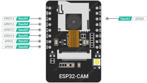
Touch Pins
The ESP32-CAM includes 7 capacitive touch-sensing GPIOs. These pins detect changes in capacitance when a capacitive load, such as a human finger, is near the GPIO. You can create a touchpad by connecting a conductive material, like aluminum foil or conductive cloth, to these pins. Due to the circuit’s high sensitivity and low noise design, even small pads are effective. Additionally, these touch pins can be used to wake the ESP32 from deep sleep.
SPI Pins
The ESP32-CAM supports one SPI (VSPI) in both slave and master modes, featuring:
- 4 timing modes for SPI format transfer
- Clock speeds up to 80 MHz
- Up to 64-byte FIFO

UART Pins
The ESP32-S chip has two UART interfaces: UART0 and UART2. However, only the RX pin (GPIO 16) of UART2 is accessible, making UART0 (GPIO 1 and GPIO 3) the primary usable UART on the ESP32-CAM. These pins are used for both flashing the board and connecting to UART devices such as GPS modules, fingerprint sensors, and distance sensors, as the ESP32-CAM does not have a USB port.

PWM Pins
The board includes 10 PWM channels (all GPIO pins) managed by a PWM controller. These channels can drive digital motors and LEDs. The PWM controller consists of PWM timers, a PWM operator, and a capture sub-module. Each timer can operate in synchronous or independent mode, and each PWM operator generates a waveform for a PWM channel. The capture sub-module accurately records external timing events.
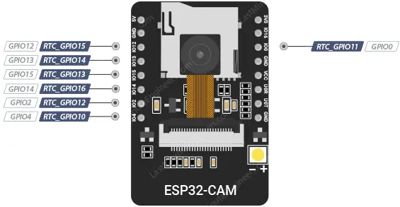
RTC GPIO Pins
RTC GPIOs are routed to the RTC low-power subsystem and can wake the ESP32 from deep sleep when the Ultra Low Power (ULP) co-processor is active. The highlighted GPIOs can be used for this purpose.
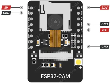
Power Pins
The ESP32-CAM has two power pins: 5V and 3.3V. You can power the device using either of these pins. However, many users have encountered issues when using the 3.3V pin, so it is recommended to always power the ESP32-CAM through the 5V pin.
The VCC pin typically outputs 3.3V from the on-board voltage regulator. However, by adjusting the Zero-ohm link near the VCC pin, it can be configured to output 5V.
GND is the ground pin.
Related article
- ESP32 Upload Error: Fix “Failed to Connect, Timed Out” Issue Fast
- How to Assign a Fixed IP Address to Your ESP32 Device
- Learn How to Set Up mDNS on ESP32 in Minutes
- ESP32 vs. ESP8266: Which Microcontroller Fits Your Requirements?
- Firebase Authentication with ESP32/ESP8266: Email and Password Guide


