

This guide teaches you how to utilize interrupts and timers with the ESP8266 NodeMCU using the Arduino IDE. Interrupts enable you to detect changes in the GPIO state without continually monitoring its current value. With interrupts, an event is triggered (a function is called) when a change is detected.
For instance, we’ll demonstrate motion detection using a PIR motion sensor: when motion is detected, the ESP8266 initiates a timer and illuminates an LED for a predetermined duration. Once the timer completes its countdown, the LED automatically turns off.
attachInterrupt() and provide the GPIO interrupt pin, the ISR (function to be called), and the mode as arguments. The ISR function must declare the ICACHE_RAM_ATTR attribute. The mode options are CHANGE, RISING, or FALLING.attachInterrupt(digitalPinToInterrupt(GPIO), ISR, mode);
Before progressing with this tutorial, ensure you have installed the ESP8266 add-on in your Arduino IDE. If not, follow the steps outlined in this tutorial to install ESP8266 in the Arduino IDE.
ESP8266 Interrupts Introduction
Interrupts play a crucial role in automating tasks within microcontroller programs and effectively managing timing concerns.
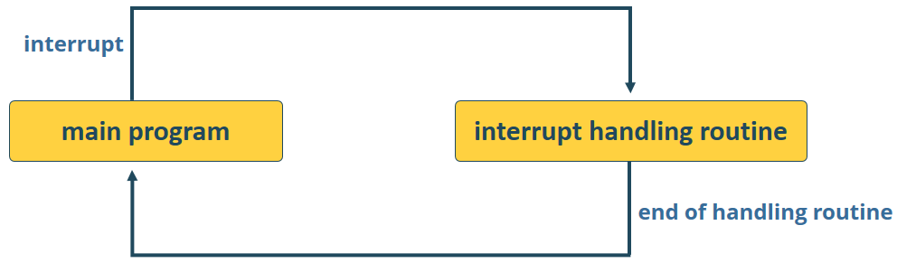
By integrating interrupts, the need for continuously monitoring the current pin value is obviated. Instead, when a change occurs, it triggers an event, prompting the execution of a designated function referred to as the interrupt service routine (ISR).
During an interrupt event, the processor momentarily interrupts the execution of the main program to execute a specific task, before returning to its original course, as illustrated in the diagram below.
This functionality proves especially beneficial for triggering actions in response to motion detection pir or pushbutton presses, eliminating the necessity for constant state checks.
Using the attachInterrupt() Function
In the Arduino IDE, you utilize the attachInterrupt() function to establish an interrupt. This function requires three arguments: the GPIO interrupt pin, the name of the function to execute, and the mode:
attachInterrupt(digitalPinToInterrupt(GPIO), ISR, mode);
GPIO interrupt pin
The initial argument specifies a GPIO interrupt. To designate the actual GPIO as an interrupt pin, utilize digitalPinToInterrupt(GPIO). For instance, to assign GPIO 14 as an interrupt, use:
digitalPinToInterrupt(14)
Interrupt Service Routine (ISR)
The second argument of the attachInterrupt() function is the function’s name that triggers each interrupt occurrence—the Interrupt Service Routine (ISR).
The ISR function should be straightforward to swiftly resume the main program’s execution.
The recommended approach involves signaling the main code of the interrupt occurrence using a global variable, checking, and clearing that flag within the loop() function, and executing the necessary code.
ISRs must include ICACHE_RAM_ATTR before the function definition to execute the interrupt code in RAM.
Interrupt modes
The third argument specifies the mode, offering three distinct options:
- CHANGE: Initiates the interrupt whenever the pin’s value changes—e.g., from HIGH to LOW or LOW to HIGH;
- FALLING: Activates when the pin transitions from HIGH to LOW;
- RISING: Triggers upon the pin transitioning from LOW to HIGH.
For our example, we’ll employ the RISING mode. Since the PIR motion sensor detects motion by causing the connected GPIO to transition from LOW to HIGH.
Introduction to ESP8266 Timers
In this tutorial, we’ll focus on timers. Our goal is to keep the LED illuminated for a set duration of time after detecting motion. Instead of relying on the delay() function, which halts code execution and restricts other tasks, we’ll utilize a timer.

delay() vs millis()
The delay() function takes a single integer argument, representing the time in milliseconds the program pauses before proceeding to the next line of code.
delay(time in milliseconds);
For instance, calling delay(1000) halts the program for 1 second. However, delay() is a blocking function, meaning it suspends all other program activities until the delay is complete. When multiple tasks need to run simultaneously, delay() becomes impractical. Therefore, it’s advisable to minimize its usage in projects and opt for timers instead.
The millis() function returns the number of milliseconds elapsed since the program began execution.
millis();
Why is this function valuable? With some mathematical calculations, you can accurately determine the elapsed time without impeding code execution.
Blinking an LED using millis() (without delay)
If you’re unfamiliar with the millis() function, we suggest reviewing this section. However, if you’re already acquainted with timers, feel free to proceed to the PIR motion sensor project.
The code snippet below demonstrates how to utilize the millis() function to execute a blink project. It involves turning an LED on for 1000 milliseconds and subsequently turning it off.
// constants won't change. Used here to set a pin number :
const int ledPin =  26;      // the number of the LED pin

// Variables will change :
int ledState = LOW;             // ledState used to set the LED

// Generally, you should use "unsigned long" for variables that hold time
// The value will quickly become too large for an int to store
unsigned long previousMillis = 0;        // will store last time LED was updated

// constants won't change :
const long interval = 1000;           // interval at which to blink (milliseconds)

void setup() {
  // set the digital pin as output:
  pinMode(ledPin, OUTPUT);
}

void loop() {
  // here is where you'd put code that needs to be running all the time.

  // check to see if it's time to blink the LED; that is, if the
  // difference between the current time and last time you blinked
  // the LED is bigger than the interval at which you want to
  // blink the LED.
  unsigned long currentMillis = millis();

  if (currentMillis - previousMillis >= interval) {
    // save the last time you blinked the LED
    previousMillis = currentMillis;

    // if the LED is off turn it on and vice-versa:
    if (ledState == LOW) {
      ledState = HIGH;
    } else {
      ledState = LOW;
    }

    // set the LED with the ledState of the variable:
    digitalWrite(ledPin, ledState);
  }
}
How the code works
Let’s delve into this blink sketch, which operates without utilizing the delay() function but instead relies on the millis() function.
Essentially, the code calculates the difference between the previous recorded time (previousMillis) and the current time (currentMillis). If the remainder exceeds the specified interval (in this case, 1000 milliseconds), the program updates the previousMillis variable to the current time and toggles the LED either on or off.
if (currentMillis - previousMillis >= interval) {
  // save the last time you blinked the LED
  previousMillis = currentMillis;
  (...)
Since this snippet is non-blocking, any code located outside of the initial if statement will function as usual.
With this understanding, you can integrate additional tasks into your loop() function without disrupting the LED blinking process.
You can upload this code to your ESP8266 for testing purposes. The onboard LED should blink every second as intended.
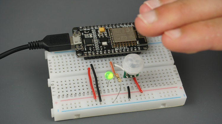
ESP8266 NodeMCU with PIR Motion Sensor
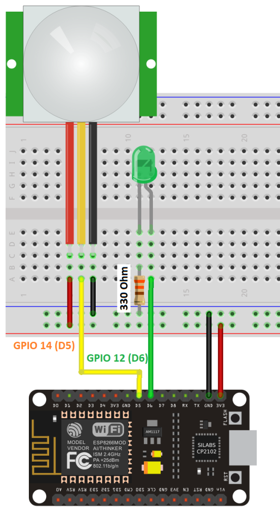
Schematic Diagram
Connect the PIR motion sensor and an LED to your ESP8266 as follows: attach the LED to GPIO 12 (D6) and the PIR motion sensor data pin to GPIO 14 (D5).
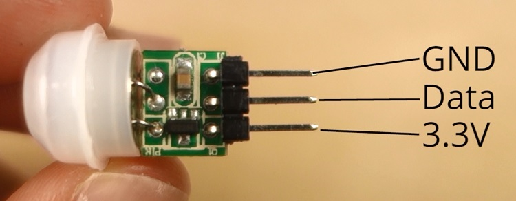
The diagram below illustrates the pinout of the AM312 PIR motion sensor.
Code
Once the circuit is wired according to the circuit diagram, copy the provided code into your Arduino IDE.
You have the option to upload the code as it is, or you can adjust the duration for which the LED remains illuminated after motion detection pir. Simply modify the timeSeconds variable to your desired number of seconds.
#define timeSeconds 10

// Set GPIOs for LED and PIR Motion Sensor
const int led = 12;
const int motionSensor = 14;

// Timer: Auxiliary variables
unsigned long now = millis();
unsigned long lastTrigger = 0;
boolean startTimer = false;

// Checks if motion was detected, sets LED HIGH and starts a timer
ICACHE_RAM_ATTR void detectsMovement() {
  Serial.println("MOTION DETECTED!!!");
  digitalWrite(led, HIGH);
  startTimer = true;
  lastTrigger = millis();
}

void setup() {
  // Serial port for debugging purposes
  Serial.begin(115200);

  // PIR Motion Sensor mode INPUT_PULLUP
  pinMode(motionSensor, INPUT_PULLUP);
  // Set motionSensor pin as interrupt, assign interrupt function and set RISING mode
  attachInterrupt(digitalPinToInterrupt(motionSensor), detectsMovement, RISING);

  // Set LED to LOW
  pinMode(led, OUTPUT);
  digitalWrite(led, LOW);
}

void loop() {
  // Current time
  now = millis();
  // Turn off the LED after the number of seconds defined in the timeSeconds variable
  if(startTimer && (now - lastTrigger > (timeSeconds*1000))) {
    Serial.println("Motion stopped...");
    digitalWrite(led, LOW);
    startTimer = false;
  }
}
How the Code Works
Let’s delve into the code’s workings.
Begin by assigning GPIO pins to the led and motionSensor variables.
const int led = 12;
const int motionSensor = 14;
Then, establish variables for setting a timer to turn off the LED after detecting motion.
unsigned long now = millis();
unsigned long lastTrigger = 0;
boolean startTimer = false;
The now variable holds the current time, lastTrigger holds the time when the PIR sensor detects motion, and startTimer is a boolean variable that initiates the timer when motion is detected.
setup()
In the setup(), start by initializing the serial port at a baud rate of 115200.
Serial.begin(115200);
Configure the PIR Motion sensor as an INPUT_PULLUP.
pinMode(motionSensor, INPUT_PULLUP);
To set the PIR sensor pin as an interrupt, employ the attachInterrupt() function as previously described.
attachInterrupt(digitalPinToInterrupt(motionSensor), detectsMovement, RISING);
GPIO 14 will detect motion and call the detectsMovement() function in RISING mode.
The LED, initially LOW, is set as an OUTPUT.
pinMode(led, OUTPUT);
digitalWrite(led, LOW);
loop()
The loop() function runs continuously. In each loop iteration, now is updated with the current time.
now = millis();
The loop() doesn’t perform any further actions. However, when motion is detected, the detectsMovement() function is invoked due to the previously set interrupt in setup().
The detectsMovement() function prints a message in the Serial Monitor, turns on the LED, sets startTimer to true, and updates lastTrigger with the current time.
ICACHE_RAM_ATTR void detectsMovement() {
  Serial.println("MOTION DETECTED!!!");
  digitalWrite(led, HIGH);
  startTimer = true;
  lastTrigger = millis();
}
Afterward, the code returns to the loop(). Now, startTimer is true. Consequently, when the specified time in seconds has elapsed since motion detection PIR, the subsequent if statement becomes true.
if(startTimer && (now - lastTrigger > (timeSeconds*1000))) {
  Serial.println("Motion stopped…");
  digitalWrite(led, LOW);
  startTimer = false;
}
The “Motion stopped…” message is printed in the Serial Monitor, the LED is turned off, and startTimer is set to false.
Demonstration
Upload the code to your ESP8266 ensuring that you’ve selected the correct board and COM port.
Open the Serial Monitor at a baud rate of 115200.

Wave your hand in front of the PIR sensor. The LED should illuminate, and a message “MOTION DETECTED!!!” should appear in the Serial Monitor. After 10 seconds, the LED should extinguish.
Wrapping Up
In conclusion, interrupts prove valuable for detecting changes in GPIO states and promptly triggering functions. Additionally, you’ve gained insight into the importance of utilizing timers to develop non-blocking code.
Explore further resources to expand your understanding of the ESP8266 board:
- ESP8266 Sensor Readings: Web Server Auto-Updates via Server-Sent Events
- Control IoT Devices: ESP8266 NodeMCU Async Web Server Tutorial
- BMP388 Barometric Sensor Setup for ESP8266 NodeMCU (Arduino IDE)
- Arduino IDE Tutorial: Using HC-SR04 Ultrasonic Sensor with ESP8266 NodeMCU


