
With the weather becoming increasingly unpredictable, it’s common to accidentally leave skylights open, leaving the area below vulnerable when sudden rain showers occur. However, by utilizing this rain sensor, you can prevent such situations.
This sensor is designed to detect rain, slushy snow, or hail, allowing you to send automatic closure commands to electronic shutters, windows, awnings, or skylights whenever rainfall is detected.
How Rain Sensor works?
The functioning of the rain sensor is quite simple.
The sensing pad consists of a set of exposed copper traces, which collectively function as a variable resistor, similar to a potentiometer. The resistance of this sensor varies depending on the amount of water present on its surface.
The resistance is directly related to the water content:
- A higher amount of water on the surface enhances conductivity and leads to a lower resistance.
- A lower amount of water on the surface reduces conductivity and results in a higher resistance.
Based on the resistance, the sensor generates an output voltage that corresponds to the presence or absence of rainfall.
Hardware Overview
A typical rain sensor consists of two main components:
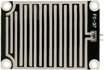
Sensing Pad
The sensor includes a sensing pad with a series of exposed copper traces. This pad is usually placed in an open area, such as on a roof, where it can be exposed to rainfall. The copper traces on the pad are not normally connected, but when water bridges the gaps between the traces, they become electrically connected.
Module
The sensor also incorporates an electronic module that connects the sensing pad to the Arduino or other microcontrollers. This module generates an output voltage based on the resistance of the sensing pad. The output voltage is provided through an Analog Output (AO) pin. Additionally, the signal is processed by an LM393 High Precision Comparator to convert it into a digital signal, which is then available at a Digital Output (DO) pin. The module features a built-in potentiometer that allows for sensitivity adjustment of the digital output.
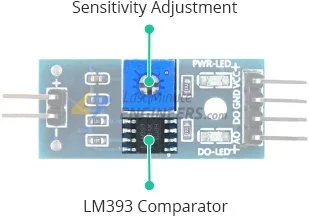
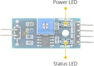
Furthermore, the module includes two LEDs. The Power LED indicates when the module is powered on, and the Status LED illuminates when the digital output goes LOW, indicating the presence of rainfall exceeding the set threshold.
Rain Sensor Pinout
The rain sensor is simple to connect and has 4 pins:
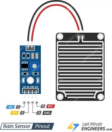
AO (Analog Output): This pin provides an analog signal ranging from the supply voltage (5V) to 0V. It can be connected to an Arduino’s analog input pin or directly to a 5V relay or similar device.
DO (Digital Output): This pin offers a digital output from the internal comparator circuit. It can be connected to any digital pin on an Arduino or directly to a 5V relay or similar device.
GND: This pin is the ground connection and should be connected to the ground of the power source.
VCC: This pin supplies power to the sensor. It is recommended to provide a voltage between 3.3V and 5V. Keep in mind that the analog output may vary depending on the voltage supplied to the sensor.
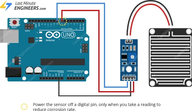
Wiring Rain Sensor with Arduino
To connect the rain sensor to the Arduino, follow these steps:
Connect the VCC pin on the sensor module to the 5V pin on the Arduino. This will provide power to the sensor.
To achieve this, connect the VCC pin on the sensor module to a digital pin on the Arduino. You can set the digital pin to either HIGH or LOW based on your requirements.
Additionally, you can power the sensor module off a digital pin on the Arduino, as the total power drawn by the module (with both LEDs lit) is around 8 mA.
Connect the GND pin on the sensor module to the ground (GND) pin on the Arduino.
Finally, connect the DO pin on the sensor module to digital pin #8 on the Arduino. This will allow you to read the digital output of the rain sensor.
Refer to the provided illustration for a visual representation of the wiring setup.
Parts Required
| Component Name | Buy Now |
| Arduino Uno REV3 | Amazon |
| LM393 Rain Drops Sensor Weather Moisture | Amazon |
| Breadboard | Amazon |
| BOJACK 1000 Pcs 25 Values Resistor Kit 1 Ohm-1M Ohm with 5% 1/4W | Amazon |
| 5mm LED Light Diodes | Amazon |
Calibrating Rain Sensor
To ensure accurate readings from your rain sensor, it is important to calibrate it before use.
The sensor module is equipped with a built-in potentiometer that allows for calibration of the digital output (DO).
By adjusting the potentiometer knob, you can set a threshold. When the amount of water surpasses this threshold value, the Status LED will illuminate, and the digital output (DO) will be set to LOW.
To calibrate the sensor, follow these steps:
- Sprinkle some water onto the sensing pad of the rain sensor.
- Adjust the potentiometer in a clockwise direction until the Status LED turns on.
- Carefully rotate the potentiometer counterclockwise until the LED goes off.
- Your sensor is now successfully calibrated and ready for use.
By following these calibration steps, you can ensure accurate and reliable readings from your rain sensor.
Detecting Rain – Arduino Code
After assembling the circuit, upload the following code to your Arduino.
Position the rain sensor in a location where it can directly receive precipitation, such as on the roof. Tilt the sensor slightly (~20°) to facilitate water flow.
Note that the electronic module is not waterproof, so be cautious when installing it to ensure only the sensing pad comes into contact with water.
// Sensor pins
#define sensorPower 7
#define sensorPin 8

void setup() {
	pinMode(sensorPower, OUTPUT);

	// Initially keep the sensor OFF
	digitalWrite(sensorPower, LOW);

	Serial.begin(9600);
}

void loop() {
	//get the reading from the function below and print it
	int val = readSensor();
	Serial.print("Digital Output: ");
	Serial.println(val);

	// Determine status of rain
	if (val) {
		Serial.println("Status: Clear");
	} else {
		Serial.println("Status: It's raining");
	}

	delay(1000);	// Take a reading every second
	Serial.println();
}

//  This function returns the sensor output
int readSensor() {
	digitalWrite(sensorPower, HIGH);	// Turn the sensor ON
	delay(10);							// Allow power to settle
	int val = digitalRead(sensorPin);	// Read the sensor output
	digitalWrite(sensorPower, LOW);		// Turn the sensor OFF
	return val;							// Return the value
}
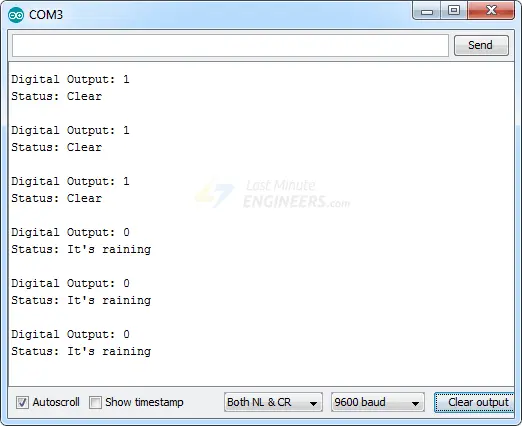
Once the code is uploaded, open the Serial Monitor window to view the Arduino’s output. When the weather is clear, you should see a digital output of HIGH. To observe the sensor detecting water, you can sprinkle some water onto the sensing pad.
Code Explanation:
The sketch begins by defining the Arduino pins to which the sensor’s VCC and DO pins are connected.
#define sensorPower 7
#define sensorPin 8
In the Setup section, we set the sensorPower pin as an output and initialize it to a low state, ensuring no power flows through the sensor initially. We also initialize the serial monitor.
pinMode(sensorPower, OUTPUT);
digitalWrite(sensorPower, LOW);
Serial.begin(9600);
Inside the loop section, we repeatedly call the readSensor() function every one second and print the returned value along with the corresponding status.
int val = readSensor();
Serial.print("Digital Output: ");
Serial.println(val);

if (val) {
	Serial.println("Status: Clear");
} else {
	Serial.println("Status: It's raining");
}

delay(1000);
We introduce a delay of 1000 milliseconds before repeating the loop.
The readSensor() function is responsible for retrieving the current digital output of the sensor. It turns the sensor ON by setting the sensorPower pin to HIGH, waits for 10 milliseconds, reads the digital value from the sensor using the sensorPin, turns the sensor OFF by setting the sensorPower pin to LOW, and finally returns the obtained value.
int readSensor() {
	digitalWrite(sensorPower, HIGH);
	delay(10);
	int val = digitalRead(sensorPin);
	digitalWrite(sensorPower, LOW);
	return val;
}
Related article
- Arduino Soil NPK Sensor: Maximizing Plant Nutrition
- Soil Moisture Sensor: How It Works and Arduino Interface Guide
- How to Interface Capacitive Soil Moisture Sensor with Arduino
- Interface Water Level Sensor with Arduino: Step-by-Step Tutorial


