
Similar to humans, your plants require nourishment to flourish. To enhance their well-being and yield, plants depend on three vital nutrients: nitrogen, phosphorus, and potassium, often known as NPKs.
Inadequate levels of these nutrients in your garden soil can impede plant growth. It is essential to evaluate the present levels of N, P, and K in the soil to determine the required nutrient supplementation for improved crop fertility.
Utilizing an NPK Soil Sensor in conjunction with an Arduino enables you to accurately measure the soil’s nutrient levels.
Parts Required
What Is NPK? and Why It’s So Important?
NPK stands for the three primary nutrients essential for the growth and flourishing of plants: nitrogen, phosphorus, and potassium.
- Nitrogen is responsible for the growth and greenness of plant leaves.
- Phosphorus helps the plant grow strong roots, fruit, and flowers.
- Potassium improves the overall health and hardiness of a plant.
JXCT Soil NPK sensor
The JXCT Soil NPK sensor is a cost-effective, rapidly responsive, reasonably precise, and portable sensor. It facilitates real-time monitoring of NPK nutrient levels in soil for smart agriculture.
This soil NPK sensor can identify nitrogen, phosphorus, and potassium levels in soil (not water), aiding in soil fertility assessment for a more systematic understanding of soil conditions.
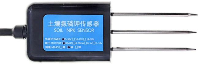
Operating on 5-30V with minimal power consumption, the sensor boasts a resolution of up to 1 mg/kg (mg/l) for nitrogen, phosphorus, and potassium measurement, as per the datasheet.
Featuring a rust-proof, electrolytic-resistant, and salt-alkali-resistant stainless steel probe, the sensor is adaptable to various soil types, including alkaline, acidic, substrate, seedling bed, and coconut bran soils.
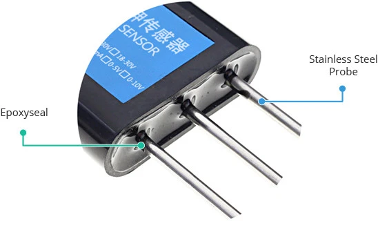
The probe is securely sealed with high-density epoxy resin to prevent moisture ingress.
Moreover, the sensor holds an IP68 rating, ensuring protection against dust and moisture, ensuring prolonged operational longevity.
For extended-range usage, the sensor incorporates an RS485 communication interface supporting the Modbus-RTU communication protocol.
However, note that direct use with Arduino isn’t possible. To interface with Arduino, an RS-485 transceiver module is required to convert UART serial stream to RS-485.
Technical Specifications
Here are the specifications:
| Power | 5V-30V |
| Measuring Range | 0-1999 mg/kg (ml/l) |
| Operating Temperature | 5-45 °C |
| Resolution | 1mg/kg (ml/l) |
| Precision | ±2% F.S. |
| Output Signal | RS485 |
| Protection Class | IP68 |
The JXCT soil NPK sensor functions as an electrical conductivity sensor (EC sensor), estimating soil NPK content based on soil electrical conductivity. This method, however, may yield inaccurate results.
It’s essential to be cautious, as similar low-cost sensors operate on the same principle.The JXCT soil NPK sensor is an electrical conductivity sensor (EC sensor). It does not directly measure the soil’s NPK content, but rather estimates it based on the electrical conductivity of the soil.
Be aware that this method is tricky and prone to producing inaccurate results.
For your information, there are inexpensive sensors out there that work on the same principle.
Soil NPK sensor Pinout
The sensor is furnished with a 2m cable containing tinned copper wires. The pinout is depicted in the figure below.
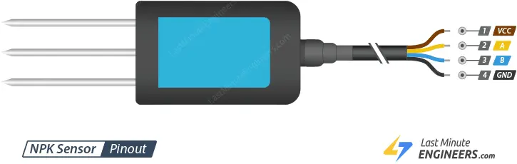
- VCC: This pin functions as the power supply input, accommodating a voltage range of 5V to 30V.
- A: A differential signal associated with the A pin of the MAX485 Modbus Module.
- B: Another differential signal connected to the B pin of the MAX485 Modbus Module.
- GND: The Ground pin.
Wiring a Soil NPK Sensor to an Arduino
As previously mentioned, direct integration of the NPK sensor with an Arduino is not feasible. To enable communication with Arduino, an RS-485 transceiver module is necessary, converting UART serial stream to RS-485, similar to the one shown below.
Let’s now proceed with the wiring.
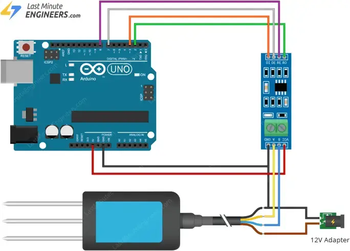
The soil NPK Sensor consists of four wires. The brown wire, indicating power, should be connected to the 5V-30V power supply. The black wire, representing ground, should be linked to a common ground.
Connect the yellow wire of the NPK sensor to the RS485 module’s A pin, and the blue wire to the RS485 module’s B pin.
Connect the RS485 module’s R0 and DI pins to Arduino’s digital pins 2 and 3, respectively. These digital pins serve as virtual RX and TX serial lines.
The RS485 module’s VCC pin should be connected to Arduino’s 5V output, and the DE and RE pins should be linked to digital pins 7 and 8, respectively.
Ensure that both your circuit and Arduino share a common ground.
The wiring configuration is illustrated in the image below.
Usage Instructions
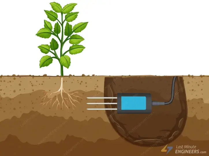
Select an appropriate measuring location, avoiding stones, and ensure that the steel probe does not encounter any hard objects. Vertically insert the sensor into the soil.

Optionally, the sensor can be inserted horizontally into a pit. In this case, excavate the pit vertically with a diameter exceeding 20 cm before tightly backfilling it.
What is Modbus?
In case you’re unfamiliar with Modbus, it’s advisable to familiarize yourself with it before proceeding.
Modbus is an industry-standard communication protocol known for its open-source and royalty-free nature. It employs RS-485, RS-422, and RS-232 interfaces, as well as Ethernet TCP/IP networks (using the Modbus TCP protocol) for data transfer.
There are several implementation types of Modbus, with the most common protocol types being:
- Modbus RTU (the one we’re configuring)
- Modbus ASCII
- Modbus TCP
Modbus RTU Protocol
Modbus RTU operates as a master-slave protocol. Within this protocol, only the master device (in our context, an Arduino) can initiate communication. Other devices on the network function as slaves (in our case, NPK sensors) and can only respond to requests. Modbus RTU can accommodate up to 247 devices on the same physical network.
Modbus RTU Data Frame
Communication over the Modbus bus occurs through the exchange of messages in the form of data frames between the master and slave. These frames comprise Request and Response segments. A request constitutes a message transmitted from the master to one of the slaves, while a response denotes a message dispatched from the slave to the master.
The request incorporates a checksum to ensure the integrity of the message during transmission to the slave.
A standard Modbus RTU message includes the SlaveID device address, the function code, data corresponding to the function code, and the CRC of the checksum.

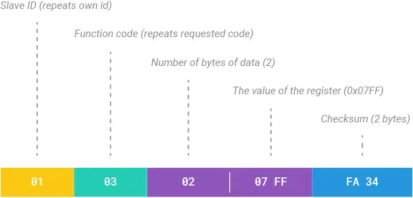
The following is an example of a Modbus RTU Request frame instructing slave #1 to return the value of a single register beginning at address 2.

All slaves except slave #1 ignore this message. Slave #1 then sends a response message that looks like this:
Modbus RTU Requests for NPK Sensor Reading
Below are three distinct Modbus RTU requests designed for retrieving the Nitrogen (N), Phosphorus (P), and Potassium (K) values from the NPK Sensor. Upon successful execution of the request, the sensor transmits a Response message containing the respective reading.
For Reading Nitrogen
The Modbus RTU request for nitrogen level reading is as follows:

Upon request completion, you will receive a response similar to:
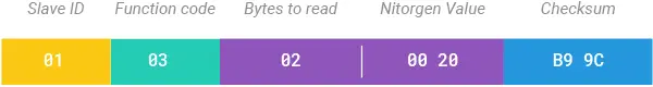
From the Response, you can extract the nitrogen level. For example, if the response includes the value 0x0020 in the data field, the nitrogen level can be calculated as follows:
Nitrogen = 0x0020HEX = 32DEC => 32 mg/kg
For Reading Phosphorous
Similarly, the Modbus RTU request for phosphorus level reading is as follows:

Upon request completion, you will receive a response akin to:
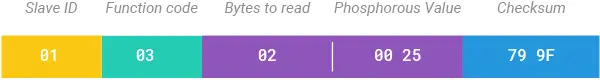
From the Response, you can extract the phosphorus level. For example, if the response contains the value 0x0025 in the data field, the phosphorus level can be calculated as follows:
Phosphorus = 0x0025HEX = 37DEC => 37 mg/kg
For Reading Potassium
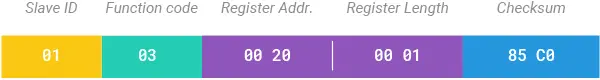
In line with the previous requests, the Modbus RTU request for potassium level reading is as follows:
Upon request completion, you will receive a response similar to:

From the Response, you can extract the potassium level. For example, if the response contains the value 0x0030 in the data field, the potassium level can be calculated as follows:
Potassium = 0x0030HEX = 48DEC => 48 mg/kg
Arduino Example Code
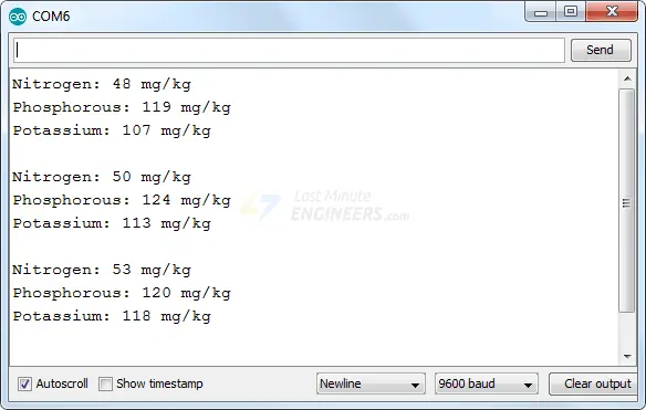
The provided test sketch retrieves the nitrogen, phosphorus, and potassium values from the soil NPK sensor and displays them on the serial monitor.
#include <SoftwareSerial.h>
#include <Wire.h>

// RE and DE Pins set the RS485 module
// to Receiver or Transmitter mode
#define RE 8
#define DE 7

// Modbus RTU requests for reading NPK values
const byte nitro[] = {0x01,0x03, 0x00, 0x1e, 0x00, 0x01, 0xe4, 0x0c};
const byte phos[] = {0x01,0x03, 0x00, 0x1f, 0x00, 0x01, 0xb5, 0xcc};
const byte pota[] = {0x01,0x03, 0x00, 0x20, 0x00, 0x01, 0x85, 0xc0};

// A variable used to store NPK values
byte values[11];

// Sets up a new SoftwareSerial object
// Digital pins 10 and 11 should be used with a Mega or Mega 2560
SoftwareSerial mod(2, 3);
//SoftwareSerial mod(10, 11);

void setup() {
  // Set the baud rate for the Serial port
  Serial.begin(9600);

  // Set the baud rate for the SerialSoftware object
  mod.begin(9600);

  // Define pin modes for RE and DE
  pinMode(RE, OUTPUT);
  pinMode(DE, OUTPUT);

  delay(500);
}

void loop() {
  // Read values
  byte val1,val2,val3;
  val1 = nitrogen();
  delay(250);
  val2 = phosphorous();
  delay(250);
  val3 = potassium();
  delay(250);

  // Print values to the serial monitor
  Serial.print("Nitrogen: ");
  Serial.print(val1);
  Serial.println(" mg/kg");
  Serial.print("Phosphorous: ");
  Serial.print(val2);
  Serial.println(" mg/kg");
  Serial.print("Potassium: ");
  Serial.print(val3);
  Serial.println(" mg/kg");

  delay(2000);
}

byte nitrogen(){
  digitalWrite(DE,HIGH);
  digitalWrite(RE,HIGH);
  delay(10);
  if(mod.write(nitro,sizeof(nitro))==8){
    digitalWrite(DE,LOW);
    digitalWrite(RE,LOW);
    for(byte i=0;i<7;i++){
    //Serial.print(mod.read(),HEX);
    values[i] = mod.read();
    Serial.print(values[i],HEX);
    }
    Serial.println();
  }
  return values[4];
}

byte phosphorous(){
  digitalWrite(DE,HIGH);
  digitalWrite(RE,HIGH);
  delay(10);
  if(mod.write(phos,sizeof(phos))==8){
    digitalWrite(DE,LOW);
    digitalWrite(RE,LOW);
    for(byte i=0;i<7;i++){
    //Serial.print(mod.read(),HEX);
    values[i] = mod.read();
    Serial.print(values[i],HEX);
    }
    Serial.println();
  }
  return values[4];
}

byte potassium(){
  digitalWrite(DE,HIGH);
  digitalWrite(RE,HIGH);
  delay(10);
  if(mod.write(pota,sizeof(pota))==8){
    digitalWrite(DE,LOW);
    digitalWrite(RE,LOW);
    for(byte i=0;i<7;i++){
    //Serial.print(mod.read(),HEX);
    values[i] = mod.read();
    Serial.print(values[i],HEX);
    }
    Serial.println();
  }
  return values[4];
}
You will see something like this.
Related article
- Step-by-Step: Connecting Reed Switch to Arduino
- Track Heart Rate: A Guide to Pulse Sensor and Arduino Integration
- Using TMP36 Temperature Sensor: Arduino Interfacing Guide
- Arduino Water Quality Testing: Utilizing the TDS Sensor
- Interfacing Arduino with TCS230/TCS3200 Color Recognition Sensor


