
Caring for a houseplant can be a challenging task, especially when it comes to remembering to water it. Fortunately, soil moisture sensors can assist us in this regard by reminding us to water our plants and promoting their longevity.
However, most inexpensive soil moisture sensors on the market are of the resistive style, featuring two prongs that measure the water content in the soil based on conductivity between them. Although they work adequately initially, they tend to rust over time, even if they have a gold-plated coating. This rusting interferes with the sensor readings, necessitating constant adjustments to the code. Additionally, they are not very effective in loose soil.
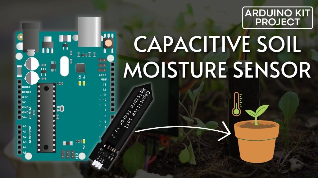
Thankfully, there is a superior alternative available: Capacitive Soil Moisture Sensors. These sensors operate based on capacitive measurement, offering several advantages over resistive measurement. They consist of a single probe, eliminating any exposed metal that may rust, and they do not pose any risk of introducing electricity into the soil, thereby ensuring the well-being of your plants.
In this tutorial, you will learn how to effectively utilize capacitive soil moisture sensors with Arduino. By the end of the tutorial, you will possess the knowledge and skills necessary to maintain thriving plants without concerns of under or overwatering. Let’s commence with the tutorial and get your plants on the path to success!
Hardware Overview
Capacitive Soil Moisture Sensors are truly remarkable devices. By simply inserting them into the soil, they generate an analog signal that corresponds to the soil’s moisture level.
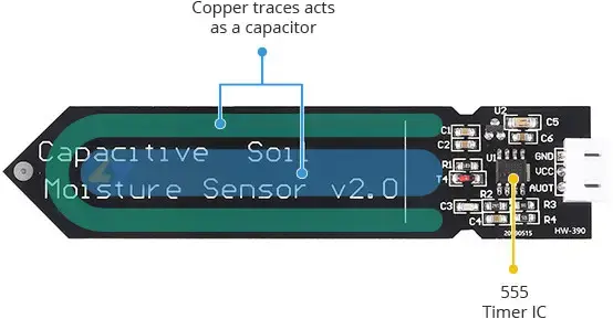
These sensors utilize a 555 timer IC and operate by measuring the charging speed of a capacitor through a resistor. However, in these sensors, the capacitor is not a physical component but is formed by two PCB traces that are in close proximity. The capacitance of these traces, and consequently their charging rate, changes in response to the surrounding water content.
The sensor is equipped with an on-board 3.3V voltage regulator, making it compatible with both 3.3V and 5V microcontrollers. Additionally, it consumes less than 5mA of current, ensuring efficient power usage.
It is important to note that this sensor can provide only a qualitative measurement of soil moisture. As the soil becomes wetter, the output value decreases, and as it becomes drier, the output value increases. When powered at 5V, the output voltage ranges from approximately 1.5V for wet soil to 3V for dry soil.
However, it’s worth mentioning that the final output value can be influenced by the depth at which the probe is inserted into the soil and the compactness of the soil around it.
Technical Specifications
Here are the specifications:
| Operating Voltage | 3.3 to 5.5V |
| Operating Current | < 5mA |
| Output Voltage at 5V | 1.5V to 3V (approx.) |
| Sensor Probe L x W (PCB) | 98 x 23mm (3.86 x 0.91″) |
| Cable Length | 20cm (8″) |
How Does a Capacitive Soil Moisture Sensor Work?
To comprehend the functioning of a capacitive soil moisture sensor, it is essential to grasp the behavior of a capacitor in an RC circuit.
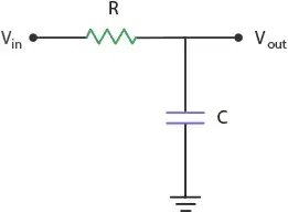
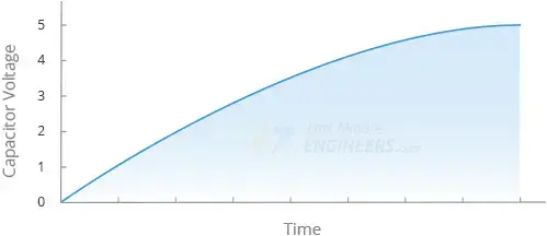
In a basic RC circuit, when a positive voltage is applied to the input, the capacitor (C) starts charging through the resistor (R). As this happens, the voltage across the capacitor changes. Gradually, the capacitor voltage increases until it matches the input voltage. A graph illustrating the voltage versus time for the charging capacitor can be observed.

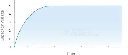
The time required for the capacitor to fully charge relies on the values of the resistor and the capacitor. If the resistor (R) remains constant and two different capacitance values are tested for the capacitor (C), it becomes evident that a larger capacitance necessitates more time to charge, whereas a smaller capacitance charges in less time.
Now, returning to our sensor, the capacitor (C) on the sensor board is not an actual component but rather two copper traces that mimic a capacitor. This phenomenon, known as Parasitic Capacitance, is common in circuits and is typically negligible. However, by intentionally enlarging the two copper traces, we can exploit this effect to our advantage.
The capacitance of this parasitic capacitor is determined by the shape of the traces and the surrounding environment (referred to as the dielectric constant). As the sensor is inserted into the soil, the environment surrounding the capacitor changes depending on whether the soil becomes wetter or drier. This alteration affects the capacitance, consequently influencing the charging time.
When the soil is dry, the capacitor exhibits a smaller capacitance, charging quickly. Conversely, when the soil is wet, the capacitor has a larger capacitance, resulting in a slower charging process.
To gain a better understanding of how this is implemented in the sensor, let’s examine the circuit diagram.
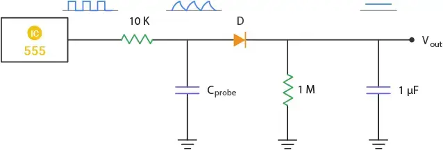
The sensor employs a 555 timer configured as an astable oscillator. The square waves generated by the 555 timer are inputted into the RC integrator, with the capacitor formed by the soil probe. The output from the integrator takes the form of a triangular wave, which is then passed through a rectifier and a smoothing capacitor to produce a DC output.
This output is directly proportional to the moisture content of the soil. Hence, when the soil is dry, the capacitor charges rapidly, leading to a greater amplitude of the triangular wave and subsequently resulting in a higher output voltage. Conversely, when the soil is wet, the capacitor charges at a slower rate, leading to a smaller amplitude of the triangular wave and consequently generating a lower output voltage.
Capacitive Soil Moisture Sensor Pinout
The capacitive soil moisture sensor is equipped with a 3-pin JST PH2.0 type connector. One end of the provided cable connects to this connector, while the other end features a standard Dupont style 3-pin female connector. The cable is conveniently color-coded to identify the function of each wire: black for ground (GND), red for power supply (VCC), and yellow for the analog voltage output (AOUT).

VCC: serves as the power supply pin. It is recommended to power the sensor with a voltage ranging from 3.3V to 5V. It’s important to note that the analog output will vary based on the voltage supplied to the sensor.
GND: represents the ground pin.
AOUT: provides an analog voltage output that corresponds to the moisture level in the soil. This output can be read using an analog input on your microcontroller. As the moisture level increases, the output voltage decreases, and conversely, as the moisture level decreases, the output voltage increases.
Usage Instructions
When utilizing the sensor, please consider the following guidelines:
Avoid placing the probe beyond the depth indicated by the limit line on the sensor.
The components on the sensor board are not waterproof. Take precautions to prevent them from coming into contact with water or splashes. To provide additional protection, you can use wide heat shrink tubing around the upper section of the board.
Take note that the edges of the PCB may absorb moisture over time, potentially reducing the sensor’s lifespan. To enhance its durability, it is advisable to apply a protective coating, such as clear epoxy. This coating will not impact the performance of the sensor.
Wiring a Capacitive Soil Moisture Sensor to an Arduino
Connecting a capacitive soil moisture sensor to an Arduino is a straightforward process. You only need to establish three connections.
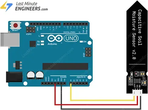
- Begin by connecting the sensor’s red wire (VCC) to the power supply. Use a voltage of 3.3V-5V, depending on the logic level of your microcontroller. For most Arduinos, a voltage of 5V is suitable. If you are using a 3.3V logic device, use 3.3V as the power supply voltage.
- Next, connect the black wire (GND) to the ground pin of your Arduino.
- Finally, connect the yellow wire (AOUT) to one of the analog input pins on your Arduino. In our example, it is connected to the A0 pin.
Refer to the following table for the pin connections:
| Soil Moisture Sensor | Arduino Pin |
|---|---|
| VCC (Red) | Power Supply (3.3V-5V) |
| GND (Black) | Ground (GND) |
| AOUT (Yellow) | Analog Input (A0) |
The wiring is shown in the image below.
Parts Required
| Component Name | Buy Now |
| Arduino Uno REV3 | Amazon |
| Capacitive Soil Moisture Sensor Module | Amazon |
| Breadboard | Amazon |
Determining the Threshold Values
While it’s not possible to directly measure the exact percentage of moisture in the soil, we can establish basic ranges to identify “too dry,” “too wet,” and “ideal” conditions. Follow these steps to find the threshold values using the provided sketch:
Upload the sketch to your Arduino.
// Define analog input
#define sensorPin A0

void setup() {
  // Setup Serial Monitor
  Serial.begin(9600);
}

void loop() {
  // Read the Analog Input
  int value = analogRead(sensorPin);

  // Print the value to the serial monitor
  Serial.print("Analog output: ");
  Serial.println(value);

  // Wait for 1 second before the next reading
  delay(1000);
}
Run the sketch and record the sensor output under the following conditions:
- When the soil is dry enough that the plant requires watering: approximately 380
- When the soil has reached the ideal moisture level for the plant: between 277 and 380
- When the soil is heavily watered and too wet (not ideal for the plant): approximately 277
- In open air: approximately 590
- In a cup of water: approximately 273
By analyzing the recorded readings in these different conditions, you can establish the threshold values that define whether the soil is too dry, too wet, or at an ideal moisture level for your plants.
Arduino Example Code
The following code provides an example of estimating soil moisture levels using the specified threshold values:
/* Adjust these values based on your observations */
#define wetSoil 277   // Maximum value considered as 'wet' soil
#define drySoil 380   // Minimum value considered as 'dry' soil

// Define analog input
#define sensorPin A0

void setup() {
  Serial.begin(9600);
}

void loop() {
  // Read the analog input and print the value
  int moisture = analogRead(sensorPin);
  Serial.print("Analog output: ");
  Serial.println(moisture);

  // Determine the status of the soil
  if (moisture < wetSoil) {
    Serial.println("Status: Soil is too wet");
  } else if (moisture >= wetSoil && moisture < drySoil) {
    Serial.println("Status: Soil moisture is optimal");
  } else {
    Serial.println("Status: Soil is too dry - time to water!");
  }
  Serial.println();

  // Take a reading every second
  delay(1000);
}
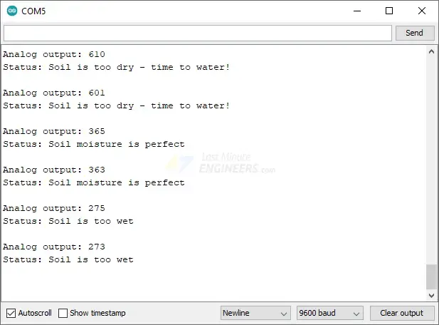
If everything is functioning correctly, you should observe similar output on the serial monitor. The code compares the sensor readings to the defined threshold values to determine if the soil is too wet, within the target moisture range, or too dry, indicating the need for watering.
Related article
- Arduino Soil NPK Sensor: Maximizing Plant Nutrition
- Step-by-Step Guide: HC-SR501 PIR Sensor Working Principles and Arduino Integration
- Understanding the Operation of HC-SR04 Ultrasonic Sensor and Connecting it to Arduino
- MQ3 Alcohol Sensor: How It Works & Arduino Integration Guide
- Interface MQ2 Gas/Smoke Sensor with Arduino: Step-by-Step Guide


