
Enhance your future Arduino project’s capability by integrating the MQ2 gas sensor module, enabling it to detect various gases such as LPG, smoke, alcohol, propane, hydrogen, methane, and carbon monoxide concentrations in the surrounding air.
The MQ2 Gas Sensor Module’s versatility makes it an ideal selection for developing applications such as indoor air quality monitoring systems, breathalyzers, or early fire detection systems.
Parts Required
| Component Name | Buy Now |
| Arduino Uno REV3 | Amazon |
| MQ-2 Gas and Smoke Analog Sensor Breakout Board | Amazon |
| Breadboard | Amazon |
MQ2 Gas Sensor
The MQ2 gas sensor is a widely used component in the MQ sensor series. It is classified as a MOS (Metal Oxide Semiconductor) sensor. This type of sensor, also known as a chemiresistor, detects gases by measuring the change in resistance of the sensing material when exposed to them.

Operating on a 5V DC power supply, the MQ2 gas sensor consumes approximately 800mW. It is capable of detecting concentrations of LPG, smoke, alcohol, propane, hydrogen, methane, and carbon monoxide within the range of 200 to 10000 ppm.
The concentration of 1 ppm represents a ratio of 1 gas molecule to 1 million gas molecules. In other words, if you were to count a million gas molecules, only one of them would be of the specific gas in question, while the rest would be other gases.
It’s important to note that while the MQ2 gas sensor can detect multiple gases, it is unable to identify them individually. This is a common characteristic of most gas sensors. Therefore, its primary use is to measure changes in the density of a known gas rather than providing specific gas identification.
Internal structure of MQ2 Gas Sensor
The MQ2 gas sensor utilizes a heater-driven design. To ensure safety when detecting flammable gases, it is equipped with two layers of fine stainless steel mesh known as an “anti-explosion network.” This protective mesh prevents the heater element inside the sensor from causing explosions.

In addition to safety, the mesh also acts as a filter, allowing only gaseous elements to pass through the sensor chamber while blocking suspended particles. The mesh is securely fastened to the sensor body using a copper-plated clamping ring.
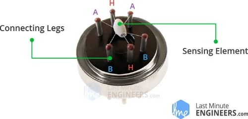
When the outer mesh is removed, the sensor’s internal structure is revealed. It consists of a star-shaped sensing element and six connecting legs extending from a Bakelite base. Two of the leads (H) are responsible for heating the sensing element and are connected by a Nickel-Chromium coil, which is a well-known conductive alloy.
The remaining four leads (A and B) are signal-carrying leads connected to the sensing element with platinum wires. These wires are linked to the body of the sensing element and detect slight variations in the current flowing through the sensing element.
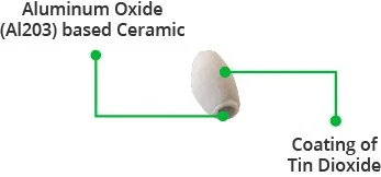
The tubular sensing element is made of Aluminum Oxide (Al2O3) based ceramic and is coated with Tin Dioxide (SnO2). The Tin Dioxide coating is the crucial material as it is highly sensitive to combustible gases. The ceramic substrate enhances heating efficiency and ensures that the sensor area is consistently heated to its operating temperature.
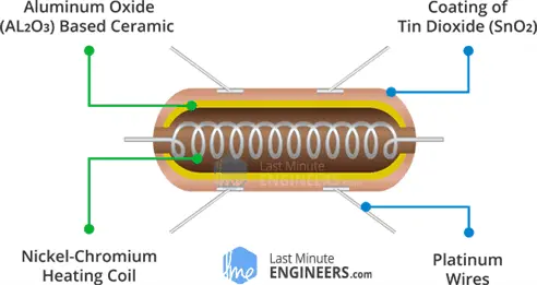
In summary, the MQ2 gas sensor’s internal structure consists of a Heating System comprising a Nickel-Chromium coil and an Aluminum Oxide-based ceramic, and a Sensing System consisting of Platinum wires and a Tin Dioxide coating.
How Gas Sensors Work
Gas sensors, such as those utilizing SnO2 semiconductor layers, operate based on a specific principle. When the SnO2 layer is heated to a high temperature, oxygen molecules are adsorbed on its surface. In clean air, the conduction band of tin dioxide releases electrons that are attracted to the adsorbed oxygen molecules. This interaction forms an electron depletion layer just below the surface of the SnO2 particles, creating a potential barrier. Consequently, the SnO2 film exhibits high resistance, blocking the flow of electric current.
However, when the surrounding environment contains reducing gases, the presence of these gases leads to a decrease in the density of adsorbed oxygen. This reduction occurs due to reactions between the oxygen and the reducing gases. As a result, the potential barrier is lowered, and electrons are released into the tin dioxide material. This allows the current to flow freely through the gas sensor, indicating the presence of reducing gases.
MQ2 Gas Sensor Module Hardware Overview
The MQ2 gas sensor module is designed for simplicity and offers two different outputs. It provides both a binary indication of the presence of combustible gases and an analog representation of their concentration in the air.

The module’s analog output voltage, accessible at the A0 pin, varies proportionally with the concentration of smoke or gas. As the concentration increases, the output voltage increases, and as the concentration decreases, the output voltage decreases. The animation below illustrates the relationship between gas concentration and output voltage.
To digitize this analog signal, the module utilizes an LM393 High Precision Comparator, which makes the digital output (D0) available.
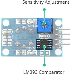
The module also features a potentiometer for adjusting the sensitivity of the digital output (D0). This allows you to set a threshold value. When the gas concentration exceeds the threshold, the module outputs LOW; otherwise, it outputs HIGH.

Furthermore, the module incorporates two LEDs. The Power LED illuminates when the module is powered on, while the Status LED lights up when the gas concentration surpasses the threshold value.
Technical Specifications
Here are the specifications:
| Operating voltage | 5V |
| Load resistance | 20 KΩ |
| Heater resistance | 33Ω ± 5% |
| Heating consumption | <800mw |
| Sensing Resistance | 10 KΩ – 60 KΩ |
| Concentration Range | 200 – 10000ppm |
| Preheat Time | Over 24 hour |
MQ2 Gas Sensor Module Pinout
Now, let’s examine the pinout of the MQ2 Gas Sensor module.

VCC: This pin is used to supply power to the module. Connect it to the 5V output of your Arduino or the appropriate power source.
GND: This pin is the ground connection and should be connected to the ground of your Arduino or the common ground.
D0: The D0 pin indicates the presence of combustible gases. When the gas concentration exceeds the threshold value set by the potentiometer, the D0 pin becomes LOW. Otherwise, it remains HIGH.
A0: The A0 pin produces an analog output voltage that is proportional to the gas concentration. Higher gas concentrations result in higher voltages, while lower concentrations yield lower voltages.
Calibrating the MQ2 Gas Sensor
Since the MQ2 gas sensor relies on a heating element, its calibration may drift if it has been in storage for a long time.
When using the sensor after an extended period of storage (a month or more), it is necessary to allow it to warm up completely for 24-48 hours to achieve optimal accuracy.
However, if the sensor has been recently used, it will only require 5-10 minutes to reach its full operating temperature. During the warm-up phase, the sensor’s readings may initially be higher and gradually decrease until they stabilize.
Experiment 1 – Measuring Gas Concentration using Analog Output (A0)
For our initial experiment, we will utilize the analog output to measure the gas concentration and determine if it falls within acceptable limits.
Wiring
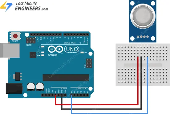
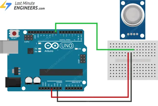
Let’s proceed with connecting the MQ2 gas sensor to the Arduino.
First, link the VCC pin of the sensor to the Arduino’s 5V pin, and then connect the GND pin to the Arduino’s Ground pin. Lastly, establish a connection between the A0 output pin of the module and Analog pin #0 on the Arduino.
Please refer to the following diagram for the wiring setup.
Determining the Threshold Value
Determining the Threshold Value
To assess if the gas concentration is within the acceptable range, you will need to record the sensor’s output values when exposed to different levels of smoke or gas.
Simply execute the provided sketch and make note of the readings.
#define MQ2pin 0

float sensorValue;  //variable to store sensor value

void setup() {
	Serial.begin(9600); // sets the serial port to 9600
	Serial.println("MQ2 warming up!");
	delay(20000); // allow the MQ2 to warm up
}

void loop() {
	sensorValue = analogRead(MQ2pin); // read analog input pin 0

	Serial.print("Sensor Value: ");
	Serial.println(sensorValue);

	delay(2000); // wait 2s for next reading
}
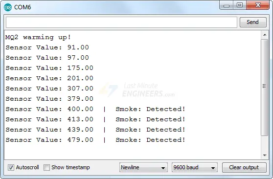
Upon running the sketch, you should observe readings similar to the examples below:
- In the absence of smoke/gas (around 100)
- In the presence of smoke/gas (around 400)
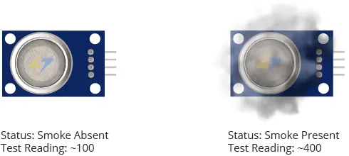
This test may require some experimentation and adjustment. Once you have obtained the readings, you can utilize them as a threshold to trigger specific actions.
Arduino Code
The sketch below determines whether the gas concentration is within acceptable limits.
/* Change the threshold value with your own reading */
#define Threshold 400

#define MQ2pin 0

float sensorValue;  //variable to store sensor value

void setup() {
	Serial.begin(9600); // sets the serial port to 9600
	Serial.println("MQ2 warming up!");
	delay(20000); // allow the MQ2 to warm up
}

void loop() {
  sensorValue = analogRead(MQ2pin); // read analog input pin 0

  Serial.print("Sensor Value: ");
  Serial.print(sensorValue);

  if(sensorValue > Threshold)
  {
    Serial.print(" | Smoke detected!");
  }

  Serial.println("");
  delay(2000); // wait 2s for next reading
}
If everything is fine, you should see something similar on the serial monitor.
Experiment 2 – Detecting the Presence of Smoke/Gas using Digital Output (D0)
In our second experiment, we will utilize the digital output to detect the presence of smoke/gas.
Wiring
We will reuse the circuit from the previous experiment. Simply disconnect the connection to the ADC pin and instead connect the D0 pin on the module to digital pin #8 on the Arduino.
Please refer to the following diagram for the wiring setup.
Setting the threshold
The module incorporates a built-in potentiometer that allows you to set the threshold for gas concentration. When the gas concentration exceeds this threshold, the module will output LOW, and the status LED will illuminate.

To set the threshold, position the gas sensor near the smoke/gas you wish to detect. Adjust the potentiometer until the Status LED starts to glow. Then, carefully rotate the potentiometer in the opposite direction until the LED turns off.
That’s all there is to it. Your module is now calibrated and ready for use.
Arduino Code
Now, upload the provided sketch to your Arduino.
#define MQ2pin 8

int sensorValue;  //variable to store sensor value

void setup() {
	Serial.begin(9600); // sets the serial port to 9600
	Serial.println("MQ2 warming up!");
	delay(20000); // allow the MQ2 to warm up
}

void loop() {
	sensorValue = digitalRead(MQ2pin); // read digital output pin
	Serial.print("Digital Output: ");
	Serial.print(sensorValue);

	// Determine the status
	if (sensorValue) {
		Serial.println("  |  Smoke: -");
	} else {
		Serial.println("  |  Smoke: Detected!");
	}

	delay(2000); // wait 2s for next reading
}
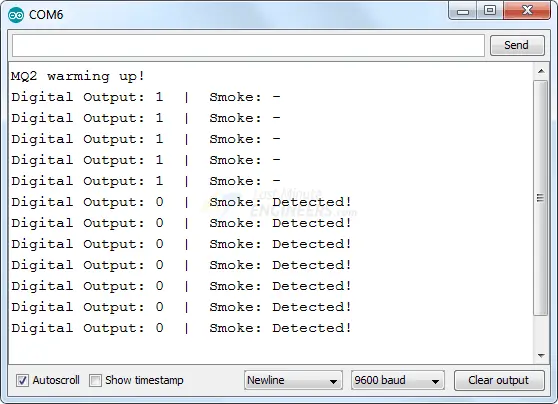
You should see similar output on the serial monitor.
Related article
- Arduino Soil NPK Sensor: Maximizing Plant Nutrition
- Step-by-Step Guide: HC-SR501 PIR Sensor Working Principles and Arduino Integration
- Understanding the Operation of HC-SR04 Ultrasonic Sensor and Connecting it to Arduino
- MQ3 Alcohol Sensor: How It Works & Arduino Integration Guide


