

Most microcontrollers (MCUs) used in our projects lack built-in timekeeping capabilities. However, for projects where accurate timekeeping is essential, the DS1307 precision RTC (Real-Time Clock) module proves to be useful. This module is ideal for a variety of applications, such as clocks, timers, alarms, data logging, and time stamping. With the DS1307 RTC module, you can ensure precise time management in your projects.
Hardware Overview
The DS1307 RTC module is built around the reliable DS1307 RTC chip and the AT24C32 EEPROM, both of which have established library support and are widely used.
DS1307 RTC Chip
The DS1307 is a cost-effective and highly accurate RTC chip from Maxim. It handles all timekeeping functions and communicates with the microcontroller through the I2C interface.
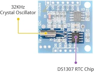
One notable feature of the DS1307 is the SQW pin, which can be programmed to generate square-wave signals at frequencies of 1Hz, 4kHz, 8kHz, or 32kHz.
To maintain precise timekeeping, the DS1307 requires an external 32kHz crystal. While the crystal frequency may be influenced by temperature variations, the impact on timekeeping accuracy is minimal. Over time, it may cause the clock to deviate by approximately two minutes per month.
Battery Backup
The DS1307 RTC module includes a battery input that ensures accurate timekeeping even during power interruptions. The built-in power-sense circuit continuously monitors the VCC status and automatically switches to the backup power supply when a power failure is detected. This allows the module to keep track of time even during power outages.
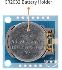
The module features a battery holder on the bottom side, designed for a 20mm 3V lithium coin cell, such as the CR2032 battery.
47mAh/300nA = 156666.67 hours = 6527.78 days = 17.87 years
Onboard 24C32 EEPROM
In addition to the RTC functionality, the DS1307 RTC module incorporates a 32-byte AT24C32 EEPROM chip. This non-volatile memory chip has 1,000,000 write cycles and can be utilized for data logging or storing other non-volatile data. The 24C32 EEPROM communicates via I2C and shares the same I2C bus as the DS1307. It has a fixed I2C address of 0x50.
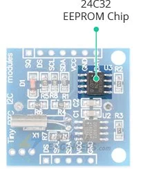
It’s important to note that writing data to the EEPROM too frequently or exceeding the specified write cycle limit can lead to premature wear and potential data loss. Therefore, it’s advisable to implement efficient data logging techniques and consider the write cycle limitation when designing your application to ensure the longevity of the EEPROM.
Module’s Hidden Feature – DS18B20
The DS1307 RTC module has an additional feature that allows the installation of a DS18B20 temperature sensor. The module provides three mounting holes in the upper right corner near the battery holder (marked U1) for installing the DS18B20.

Once the DS18B20 temperature sensor is installed, temperature readings can be obtained from the DS pin. These readings can be used to compensate for temperature-induced time drift. Proper installation involves soldering the DS18B20 according to the polarity shown on the silk screen, and a 4.7K resistor may be required between VCC and DS.
I2C Interface
The module utilizes a simple I2C interface and occupies two addresses. The DS1307 RTC chip has a fixed I2C address of 0x68, while the 24C32 EEPROM has a fixed I2C address of 0x50.
The SDA and SCL signals, as well as power and ground, are accessible on the other side of the module, allowing easy connection to other modules.
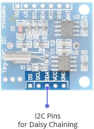
To ensure reliable communication, both the SDA and SCL lines are equipped with 4.7K pull-up resistors.
Technical Specifications
Here are the specifications:
| Operating Voltage | 4.5 to 5.5V (5V typical) |
| Current Consumption | < 1.5mA (typ.) |
| Accuracy (0-40°C) | Depends on crystal (± 20ppm typ.) |
| Battery | CR2032 (3V Coin) |
For more information on the DS1307 RTC and the 24C32 EEPROM chip, please refer to the datasheets listed below.
DS1307 RTC Module Pinout
The DS1307 RTC module features a total of 7 pins. Here is the pinout:
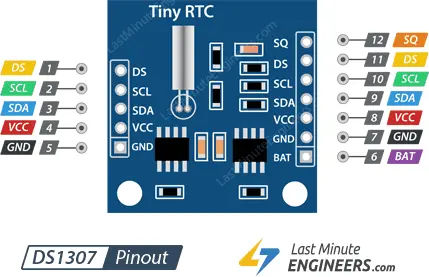
SQW: This pin is responsible for outputting one of four square-wave frequencies: 1Hz, 4kHz, 8kHz, or 32kHz.
DS: If a DS18B20 temperature sensor is installed using the designated mounting holes near the battery holder (marked U1), this pin should provide temperature readings.
SCL: This pin serves as the serial clock for the I2C interface.
SDA: This pin functions as the serial data for the I2C interface.
VCC: This pin supplies power to the module and can be connected to a 5-volt power supply.
GND: This pin serves as the ground connection.
BAT: To ensure accurate timekeeping during power interruptions, this pin is used for a backup supply input. It is designed to accommodate a standard 3V lithium cell or any other suitable energy source.
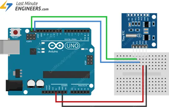
Wiring a DS1307 RTC Module to an Arduino
To connect the RTC module to an Arduino, follow these simple steps:
- Connect the VCC pin of the RTC module to the 5V output of the Arduino.
- Connect the GND pin of the RTC module to the ground (GND) of the Arduino.
- Connect the SDA (data line) pin of the RTC module to the SDA (A4) pin of the Arduino.
- Connect the SCL (clock line) pin of the RTC module to the SCL (A5) pin of the Arduino.
Make sure to verify the correct I2C pins on your specific Arduino board, as they may vary. Refer to the following table for a quick reference:
| SCL | SDA | |
| Arduino Uno | A5 | A4 |
| Arduino Nano | A5 | A4 |
| Arduino Mega | 21 | 20 |
| Leonardo/Micro | 3 | 2 |
With these connections in place, the RTC module is ready to be used with the Arduino.
Parts Required
| Component Name | Buy Now |
| Arduino Uno REV3 | Amazon |
| 2C RTC DS1307 Real Time Clock Module | Amazon |
| Breadboard | Amazon |
| BOJACK 1000 Pcs 25 Values Resistor Kit 1 Ohm-1M Ohm with 5% 1/4W | Amazon |
Installing uRTCLib Library
To simplify communication with the RTC module and enable easy reading of RTC data, we can use the uRTCLib library. This powerful library also supports programming the SQW output, a feature that is not commonly available in other RTC libraries.
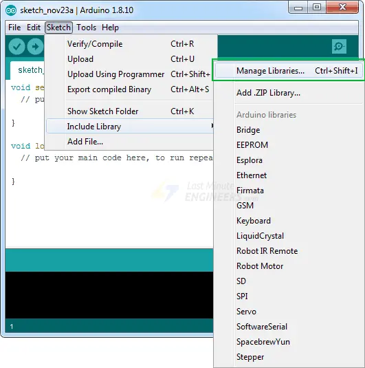
To install the library, follow these steps:
Open the Arduino IDE and navigate to Sketch > Include Library > Manage Libraries…
Wait for the Library Manager to load and update the list of available libraries.
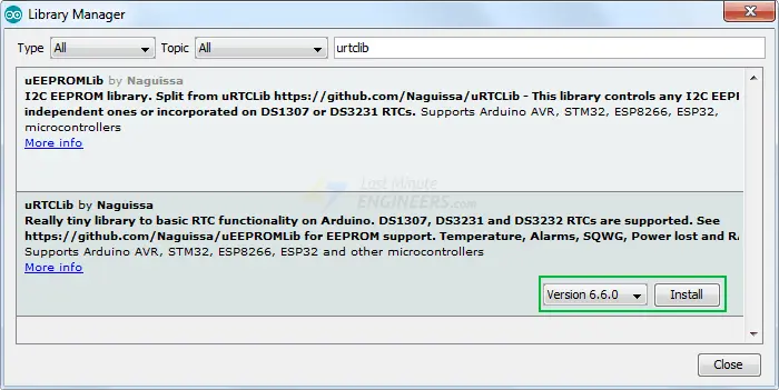
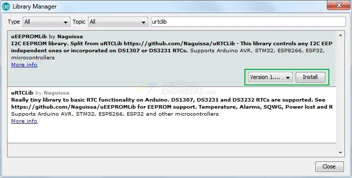
In the search bar, enter ‘urtclib’ to filter the results.
Look for the entry named ‘uRTCLib’ by Naguissa and click on it.
Click the ‘Install’ button to install the uRTCLib library.
Additionally, if you are interested in reading and writing data to the onboard 24C32 EEPROM, you will need to install the uEEPROMLib library. To install this library, follow the same steps as above, but search for ‘ueepromlib’ instead and install the corresponding library.
Once the libraries are installed, you can use them in your Arduino code to interact with the RTC module and EEPROM, if needed.
Arduino Code – Reading Date and Time
This is a simple sketch for setting/reading the date and time from the DS1307 RTC module.
#include "Arduino.h"
#include "uRTCLib.h"

// uRTCLib rtc;
uRTCLib rtc(0x68);

char daysOfTheWeek[7][12] = {"Sunday", "Monday", "Tuesday", "Wednesday", "Thursday", "Friday", "Saturday"};

void setup() {
  Serial.begin(9600);
  delay(3000); // wait for console opening

  URTCLIB_WIRE.begin();

  // Comment out below line once you set the date & time.
  // Following line sets the RTC with an explicit date & time
  // for example to set January 13 2022 at 12:56 you would call:
   rtc.set(0, 56, 12, 5, 13, 1, 22);
  // rtc.set(second, minute, hour, dayOfWeek, dayOfMonth, month, year)
  // set day of week (1=Sunday, 7=Saturday)
}

void loop() {
  rtc.refresh();

  Serial.print("Current Date & Time: ");
  Serial.print(rtc.year());
  Serial.print('/');
  Serial.print(rtc.month());
  Serial.print('/');
  Serial.print(rtc.day());

  Serial.print(" (");
  Serial.print(daysOfTheWeek[rtc.dayOfWeek()-1]);
   Serial.print(") ");

  Serial.print(rtc.hour());
  Serial.print(':');
  Serial.print(rtc.minute());
  Serial.print(':');
  Serial.println(rtc.second());

  delay(1000);
}
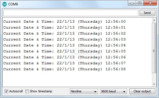
Here’s what the output looks like:
Code Explanation:
The code begins by including the necessary libraries, Arduino.h and uRTCLib.h, to enable communication with the module. An object of the uRTCLib library is created, and a 2D character array, daysOfTheWeek, is defined to store the days’ information.
In the setup and loop sections of the code, the following functions are used to interact with the RTC module:
- The
begin()function ensures proper initialization of the RTC module.
- The
set(ss, mm, hh, day, dd, mm, yy)function sets the RTC to a specific date and time. For example, to set the RTC to January 13, 2022, at 12:56, you would call:rtc.set(0, 56, 12, 5, 13, 1, 22);
- The
refresh()function updates data from the hardware RTC.
- The
year()function returns the current year.
- The
month()function returns the current month.
- The
day()function returns the current day.
- The
dayOfWeek()function returns the current day of the week as a value between 1 and 7. This function is typically used as an index to access the daysOfTheWeek array and retrieve information about the day.
- The
hour()function returns the current hour.
- The
minute()function returns the current minute.
- The
second()function returns the current second.
These functions provide easy access to the RTC data, allowing you to retrieve and utilize the date and time information as needed in your Arduino project.
Arduino Code – Read/Write the 24C32 EEPROM
The code provided below demonstrates how to write and read data from the 24C32 EEPROM on the DS1307 RTC module. It showcases writing an integer, float, character, and string to the EEPROM, and then reading them back. This sketch serves as a foundation for saving various settings, passwords, or any other data you need to store.
#include "Arduino.h"
#include "Wire.h"
#include "uEEPROMLib.h"

// uEEPROMLib eeprom;
uEEPROMLib eeprom(0x50);

void setup() {
  Serial.begin(9600);
  delay(2500);

  Wire.begin();

  int inttmp = 32123;
  float floattmp = 3.1416;
  char chartmp = 'A';
  char c_string[] = "lastminuteengineers.com"; //23
  int string_length = strlen(c_string);

  Serial.println("Writing into memory...");

  // Write single char at address
  if (!eeprom.eeprom_write(8, chartmp)) {
  Serial.println("Failed to store char.");
  } else {
  Serial.println("char was stored correctly.");
  }

  // Write a long string of chars FROM position 33 which isn't aligned to the 32 byte pages of the EEPROM
  if (!eeprom.eeprom_write(33, (byte *) c_string, strlen(c_string))) {
  Serial.println("Failed to store string.");
  } else {
  Serial.println("string was stored correctly.");
  }

  // Write an int
  if (!eeprom.eeprom_write(0, inttmp)) {
    Serial.println("Failed to store int.");
  } else {
    Serial.println("int was stored correctly.");
  }

  // write a float
  if (!eeprom.eeprom_write(4, floattmp)) {
    Serial.println("Failed to store float.");
  } else {
    Serial.println("float was stored correctly.");
  }

  Serial.println("");
  Serial.println("Reading memory...");

  Serial.print("int: ");
  eeprom.eeprom_read(0, &inttmp);
  Serial.println(inttmp);

  Serial.print("float: ");
  eeprom.eeprom_read(4, &floattmp);
  Serial.println((float) floattmp);

  Serial.print("char: ");
  eeprom.eeprom_read(8, &chartmp);
  Serial.println(chartmp);

  Serial.print("string: ");
  eeprom.eeprom_read(33, (byte *) c_string, string_length);
  Serial.println(c_string);

  Serial.println();
}

void loop() {
}
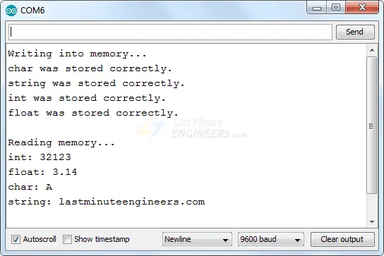
Here’s what the output looks like:
To ensure proper storage, it’s necessary to account for the memory requirements of each data type. For instance, when storing a character, you can write it to consecutive memory locations (0, 1, 2, 3, 4, 5, …). However, when storing an integer, you must reserve two memory locations for each value, so you should store data in every other memory location (0, 2, 4, 6, …).
By considering the memory usage of different data types, you can effectively manage the allocation and retrieval of data within the EEPROM.
Related article
- Arduino BMP180 Guide: Barometric Pressure and Temperature
- Using TMP36 Temperature Sensor: Arduino Interfacing Guide
- Step-by-Step Guide: LM35 Temperature Sensor Interfacing with Arduino
- DS3231 RTC Module: Seamless Integration with Arduino
- Arduino Tutorial: Connecting TM1637 7-Segment Display Effortlessly


