
We understand that many microcontrollers (MCUs) utilized in our projects operate without consideration of time; they lack awareness of their temporal surroundings. While this suffices for the majority of our endeavors, occasionally, the need arises for precise timekeeping. In such cases, the DS3231 Precision Real-Time Clock (RTC) module proves invaluable. It serves a multitude of purposes across various projects, from clocks, timers, and alarms to data logging and time stamping.
Parts Required
Hardware Overview
This module integrates the DS3231S RTC chip and the AT24C32 EEPROM. Both components have a well-established reputation and are supported by extensive libraries.
DS3231 RTC Chip
At the heart of the module is the DS3231, a cost-effective and highly accurate RTC chip manufactured by Maxim. Responsible for all timekeeping functions, it communicates with the microcontroller via I2C.

The DS3231 effectively tracks seconds, minutes, hours, days, dates, months, and years. It automatically adjusts dates for months with fewer than 31 days, including leap year corrections (applicable up to 2100).
Operating in either a 12-hour or 24-hour format, it includes an AM/PM indicator and accommodates two programmable time-of-day alarms.
The INT/SQW pin on the DS3231 serves as either an interrupt signal (for alarm conditions) or generates a square wave at 1Hz, 4kHz, 8kHz, or 32kHz.
Moreover, the DS3231 provides a stable and precise reference clock on the 32K pin, temperature-compensated, which is advantageous for ensuring clock timing accuracy or clocking other circuits.
Temperature Compensated Crystal Oscillator(TCXO)
In contrast to most RTC modules like the DS1307, which rely on an external 32kHz crystal oscillator for timekeeping, the DS3231 utilizes a 32kHz temperature-compensated crystal oscillator (TCXO). This TCXO minimizes the impact of external temperature changes on oscillation frequency.
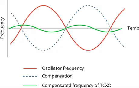
Comprising an integrated temperature sensor, a 32kHz crystal oscillator, and control logic, the TCXO adjusts clock ticks to compensate for frequency variations, ensuring precise timekeeping.
Thanks to the TCXO, the module offers a stable and accurate reference clock, maintaining RTC accuracy within ±2 minutes per year.
The primary difference between the DS3231 and DS1307 lies in timekeeping accuracy. While the DS1307 requires an external 32kHz crystal oscillator susceptible to temperature fluctuations, resulting in clock inaccuracies of around five minutes per month, the DS3231 provides superior accuracy.
With its internal Temperature Compensated Crystal Oscillator (TCXO), impervious to temperature effects, the DS3231 achieves higher accuracy, typically within a few minutes per year.
Although the DS1307 remains a dependable RTC, for projects demanding enhanced timekeeping precision, the DS3231 emerges as the preferred choice.
Battery Backup
The DS3231 IC features a battery input to ensure precise timekeeping even during interruptions to the main power source.
A built-in power-sense circuit continuously monitors VCC status, detecting power failures and seamlessly switching to the backup supply. Consequently, even in the event of a power outage, the IC maintains accurate timekeeping.
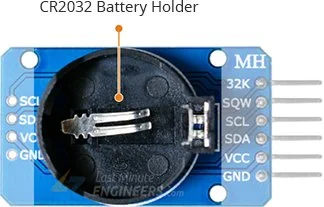
For backup power, the board includes a battery holder for a 20mm 3V lithium coin cell, located at the bottom.
220mAh/3µA = 73333.34 hours = 3055.56 days = 8.37 years
Onboard 24C32 EEPROM
The DS3231 RTC module also incorporates a 32-byte (4K x 8-bits) AT24C32 EEPROM chip (non-volatile) with 1,000,000 write cycles. Although unrelated to the RTC, this chip proves beneficial for tasks like data logging or storing non-volatile data.
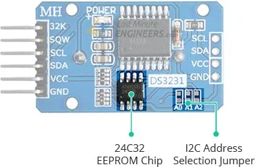
The 24C32 EEPROM communicates via I2C and shares the same I2C bus as the DS3231.
When using multiple devices on the same I2C bus, it may be necessary to assign a different I2C address for the EEPROM to prevent conflicts with other I2C devices.
To achieve this, the module features three solder jumpers (A0, A1, and A2) on the back. Shorting a jumper with solder sets the address.
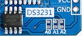
According to the 24C32 datasheet, these three bits are positioned at the end of the seven-bit I2C address, just before the Read/Write bit.

With three address inputs that can be either HIGH or LOW, eight (2^3) different addresses can be created.
By default, all three address inputs are pulled HIGH using onboard pullups, resulting in a default I2C address of 1010111Binary or 0x57Hex for the 24C32.
Shorting the solder jumpers pulls the address inputs LOW, enabling customization of the I2C address as indicated in the table below.
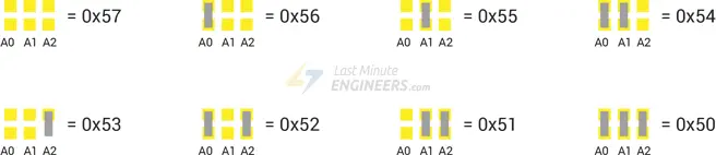
I2C Interface
The module features a straightforward I2C interface occupying two addresses. The DS3231S RTC chip’s fixed I2C address is 0x68, while the EEPROM defaults to 0x57 (although its address range spans from 0x50 to 0x57).
The I2C SDA and SCL signals, along with power and ground connections, are accessible on one side of the module, facilitating their extension to another module.
To facilitate communication, both SDA and SCL lines include 4.7K pull-up resistors.
Technical Specifications
Here are the specifications:
| Operating Voltage | 2.3 to 5.5V (3.3 or 5V typical) |
| Current Consumption | < 300µA (typ.) |
| Accuracy (0-40°C) | ± 2ppm |
| Battery | CR2032 (3V Coin) |
For detailed information regarding the DS3231 RTC and the 24C32 EEPROM chip, please consult the provided datasheets.
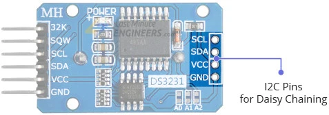
These modules typically include a 200Ω resistor adjacent to the 1N4148 diode, as shown in the image below.
This resistor and diode combination forms a basic charging circuit intended for use with LIR2032 rechargeable batteries.
It’s important to note that certain DS3231 modules are equipped with a non-rechargeable CR2032 battery. In such cases, the resistor must be removed to avoid potential damage, as attempting to charge a non-rechargeable battery can have serious consequences.
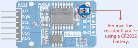
DS3231 RTC Module Pinout
The DS3231 RTC module features a total of 6 pins, with the following pinout:
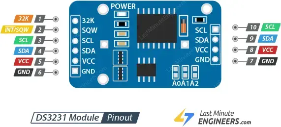
- The 32K pin outputs a stable, temperature-compensated, and accurate reference clock.
- The INT/SQW pin provides either an interrupt signal (indicating alarm conditions) or a square-wave output at frequencies of 1Hz, 4kHz, 8kHz, or 32kHz.
- SCL serves as the serial clock pin for the I2C interface.
- SDA acts as the serial data pin for the I2C interface.
- VCC supplies power to the module, and it can be connected to a power supply ranging from 3.3 to 5 volts.
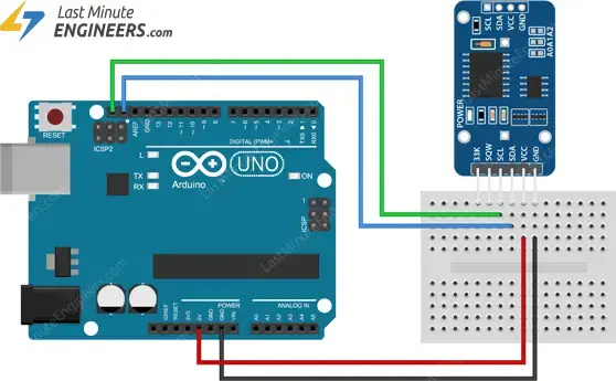
Wiring a DS3231 RTC module to an Arduino
Let’s establish the connection between the RTC and the Arduino.
The connections are simple. Start by linking the VCC pin to the Arduino’s 5V output and the GND pin to the ground.
Next, focus on the pins designated for I2C communication. It’s essential to connect them correctly, noting that different Arduino boards have distinct I2C pin configurations. On Arduino boards following the R3 layout, the SDA (data line) and SCL (clock line) pins are located near the pin headers close to the AREF pin. These pins are also known as A5 (SCL) and A4 (SDA).
The table below outlines the pin connections:
| DS3231 Module | Arduino |
| VCC | 5V |
| GND | GND |
| SCL | SCL or A5 |
| SDA | SDA or A4 |
The diagram below shows how to connect everything.
Installing uRTCLib Library
Communicating with an RTC module can be a daunting task. Fortunately, the uRTCLib library simplifies this process by abstracting away the complexities, enabling us to issue straightforward commands for reading RTC data.
This library, though simple, offers robust functionality, including support for time-of-day alarms and programming the SQW output, a feature absent in many RTC libraries.
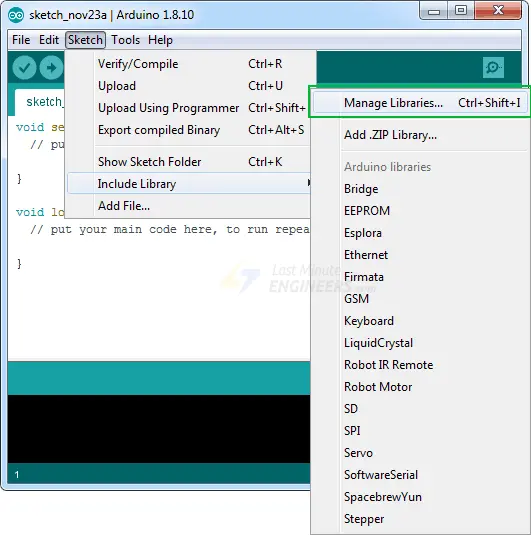
To install the library, follow these steps:
Navigate to Sketch > Include Library > Manage Libraries…
Wait for the Library Manager to download the library index and update the list of installed libraries.
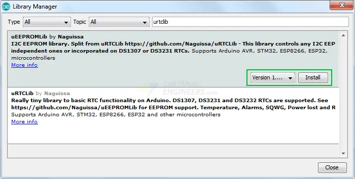
Filter your search by entering ‘urtclib’.
Locate uRTCLib by Naguissa.
Click on the entry, then choose Install.

Additionally, towards the conclusion of the tutorial, we provide code snippets for reading and writing data to the onboard 24C32 EEPROM. If you wish to utilize this functionality, you’ll need to install the uEEPROMLib library as well. Search for ‘ueepromlib’ and proceed with the installation.
Arduino Code – Reading Date, Time and Temperature
This is a simple sketch for setting/reading the date, time, and temperature from the DS3231 RTC module.
#include "Arduino.h"
#include "uRTCLib.h"

// uRTCLib rtc;
uRTCLib rtc(0x68);

char daysOfTheWeek[7][12] = {"Sunday", "Monday", "Tuesday", "Wednesday", "Thursday", "Friday", "Saturday"};

void setup() {
  Serial.begin(9600);
  delay(3000); // wait for console opening

  URTCLIB_WIRE.begin();

  // Comment out below line once you set the date & time.
  // Following line sets the RTC with an explicit date & time
  // for example to set January 13 2022 at 12:56 you would call:
   rtc.set(0, 56, 12, 5, 13, 1, 22);
  // rtc.set(second, minute, hour, dayOfWeek, dayOfMonth, month, year)
  // set day of week (1=Sunday, 7=Saturday)
}

void loop() {
  rtc.refresh();

  Serial.print("Current Date & Time: ");
  Serial.print(rtc.year());
  Serial.print('/');
  Serial.print(rtc.month());
  Serial.print('/');
  Serial.print(rtc.day());

  Serial.print(" (");
  Serial.print(daysOfTheWeek[rtc.dayOfWeek()-1]);
  Serial.print(") ");

  Serial.print(rtc.hour());
  Serial.print(':');
  Serial.print(rtc.minute());
  Serial.print(':');
  Serial.println(rtc.second());

  Serial.print("Temperature: ");
  Serial.print(rtc.temp()  / 100);
  Serial.print("\xC2\xB0");   //shows degrees character
  Serial.println("C");

  Serial.println();
  delay(1000);
}
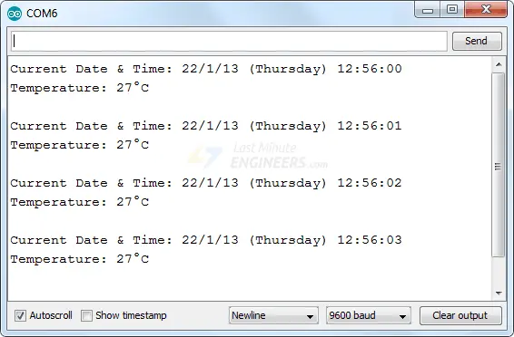
Here’s what the output looks like:
Explanation of the Code:
The sketch starts by including the Arduino.h and uRTCLib.h libraries, facilitating communication with the module. Subsequently, an object of the uRTCLib library is created, and the daysOfTheWeek 2D character array is defined to store information about the days.
To interact with the RTC module, the following functions are employed within the setup and loop sections of the code:
The begin() function ensures proper initialization of the RTC module.
The set(ss, mm, hh, day, dd, mm, yy) function sets the RTC to a specific date and time. For instance, to set January 13, 2022, at 12:56, the call would be rtc.set(0, 56, 12, 5, 13, 1, 22).
The refresh() function updates data from the hardware RTC.
The year() function returns the current year.
The month() function returns the current month.
The day() function returns the current day.
The dayOfWeek() function returns the current day of the week (1 to 7). Typically, this function serves as an index for a 2D character array storing day-related information.
The hour() function returns the current hour.
The minute() function returns the current minute.
The second() function returns the current seconds.
The temp() function retrieves the current temperature of the ‘die’.
Arduino Code – Read/Write the 24C32 EEPROM
As an additional feature, the DS3231 RTC module incorporates 32 bytes of Electrically Erasable ROM (EEPROM). Its contents remain intact even in the event of a power interruption.
The following is a straightforward sketch designed to write an integer, float, character, and string to the 24C32 EEPROM, subsequently reading them back. This sketch can be expanded to store various settings, passwords, or other data.
#include "Arduino.h"
#include "Wire.h"
#include "uEEPROMLib.h"

// uEEPROMLib eeprom;
uEEPROMLib eeprom(0x57);

void setup() {
  Serial.begin(9600);
  delay(2500);

  Wire.begin();

  int inttmp = 32123;
  float floattmp = 3.1416;
  char chartmp = 'A';
  char c_string[] = "lastminuteengineers.com"; //23
  int string_length = strlen(c_string);

  Serial.println("Writing into memory...");

  // Write single char at address
  if (!eeprom.eeprom_write(8, chartmp)) {
  Serial.println("Failed to store char.");
  } else {
  Serial.println("char was stored correctly.");
  }

  // Write a long string of chars FROM position 33 which isn't aligned to the 32 byte pages of the EEPROM
  if (!eeprom.eeprom_write(33, (byte *) c_string, strlen(c_string))) {
  Serial.println("Failed to store string.");
  } else {
  Serial.println("string was stored correctly.");
  }

  // Write an int
  if (!eeprom.eeprom_write(0, inttmp)) {
    Serial.println("Failed to store int.");
  } else {
    Serial.println("int was stored correctly.");
  }

  // write a float
  if (!eeprom.eeprom_write(4, floattmp)) {
    Serial.println("Failed to store float.");
  } else {
    Serial.println("float was stored correctly.");
  }

  Serial.println("");
  Serial.println("Reading memory...");

  Serial.print("int: ");
  eeprom.eeprom_read(0, &inttmp);
  Serial.println(inttmp);

  Serial.print("float: ");
  eeprom.eeprom_read(4, &floattmp);
  Serial.println((float) floattmp);

  Serial.print("char: ");
  eeprom.eeprom_read(8, &chartmp);
  Serial.println(chartmp);

  Serial.print("string: ");
  eeprom.eeprom_read(33, (byte *) c_string, string_length);
  Serial.println(c_string);

  Serial.println();
}

void loop() {
}
Here’s a preview of the output:
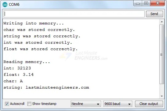
Essentially, when storing a character, it can be written to each memory location (0, 1, 2, 3, 4, 5, …).
However, if storing an integer, two memory locations must be reserved for each value, necessitating data storage in alternate memory locations (0, 2, 4, 6, …).
Related article
- DIY Project: Arduino Interface for TFMini-S LiDAR Sensor
- Understanding Accelerometers: Interface ADXL335 with Arduino
- Arduino Soil NPK Sensor: Maximizing Plant Nutrition
- Step-by-Step: Connecting Reed Switch to Arduino
- Track Heart Rate: A Guide to Pulse Sensor and Arduino Integration
- Using TMP36 Temperature Sensor: Arduino Interfacing Guide


