

Flashy flashing LEDs might not be the most ideal lighting choice, but they’re sure to add excitement to any gathering. And since a party devoid of music lacks zest, synchronizing both can greatly enhance the ambiance.
When it comes to lighting that reacts to sound, WLED stands out as the premier option. It’s a free, feature-packed, open-source mobile application that grants complete control over a diverse range of NeoPixel LEDs. By utilizing a MAX4466-amplified microphone linked to an ESP32, this application enables you to synchronize LED strips with music. Furthermore, you have the option to choose from over 30 unique sound-reactive effects and more than 70 color palettes to elevate the party atmosphere.
This guide will instruct you on connecting a WS2812B LED strip and a MAX4466 microphone amplifier module to an ESP32 board, as well as installing WLED-SR, the sound-reactive iteration of WLED.
Parts Required
| Component Name | Buy Now |
| ESP32-WROOM-32 Development | Amazon |
| WS2812B RGB ECO LED Strip | Amazon |
| Microphone Amplifier Module MAX4466 | Amazon |
Materials Required
To undertake this project, you’ll require the following items:
- An ESP32 Development board
- A WS2812B addressable LED strip
- A MAX4466 microphone amplifier module
- A 5V power supply (with a minimum rating of 3A)
Configuring WLED-SR on an ESP32 Board
The process of setting up custom firmware like WLED-SR on an ESP32 Board has been simplified by WLED. Follow these steps to complete the installation:
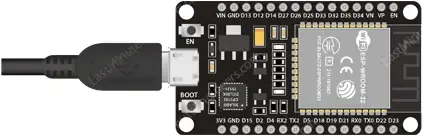
- Connect your ESP32 board to your computer using a USB cable. Ensure the cable supports data transfer.
- Open a web browser and visit install.wled.me. This URL will lead you to the website interface.
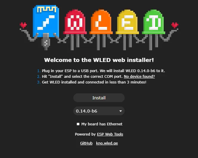
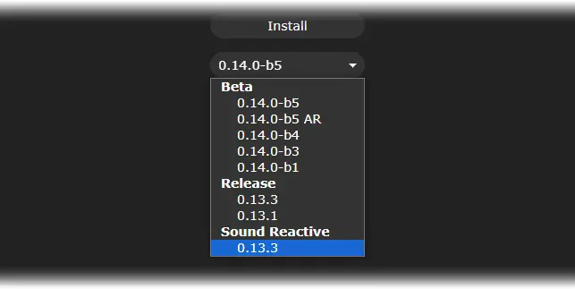
- From the dropdown menu, choose the “sound-reactive” version of WLED, listed as the last option.
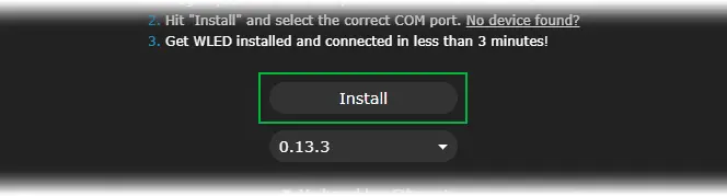
- Click Install.
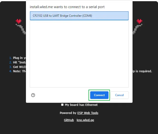
- Select the COM port to which your ESP32 is connected and click Connect. WLED uses Web Serial API to access serial ports.
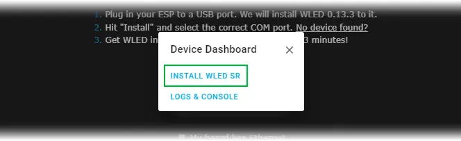
- Click ‘Install WLED SR’ to start the process.
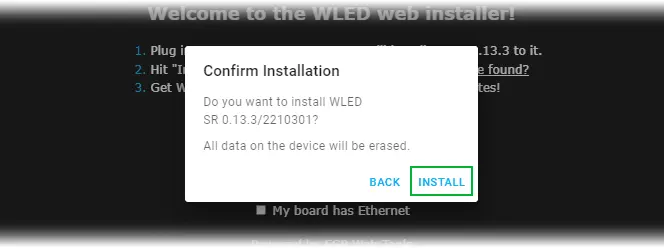
- Confirm the installation to flash the firmware onto the board. This step is a final warning, as it erases all existing data.
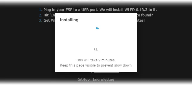
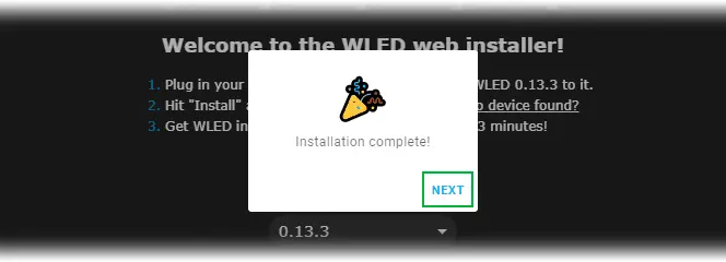
- The installation process will begin. Release the BOOT button when the connection is established. Installation typically takes a few minutes.
- Click Next to complete the installation.
- Check the Network icon on the taskbar for a new wireless access point named WLED-AP.
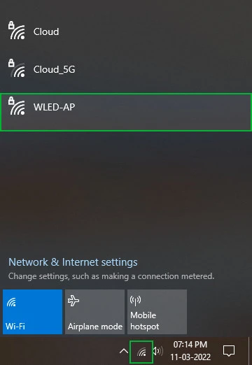
- Connect to it and enter wled1234 if prompted for a password.

- Once connected, your default browser will automatically load the WLED home page. If not, manually navigate to http://4.3.2.1.
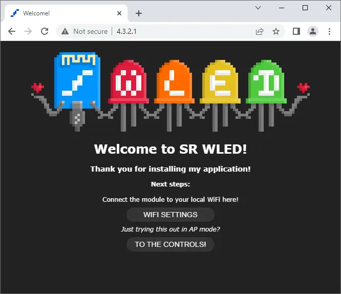
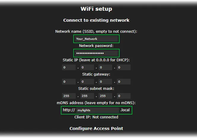
- Go to WIFI Settings to access the WIFI Setup section.
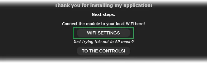
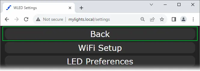
Adjust the Network Name and Network Password to match your WiFi network credentials. Set the mDNS address as desired, e.g., http://mylights.local/. This address will be used to access your lights via a web browser on your WiFi network.
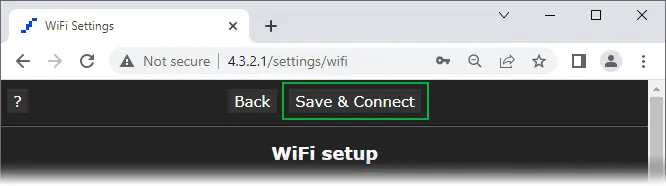
- Click Save and Connect. The ESP32 will reboot and connect to your WiFi network. Reset the ESP32 by pressing the EN button as a precaution.
- Reconnect to your home network.
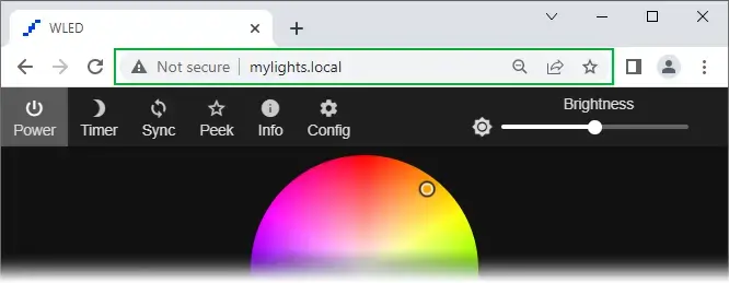
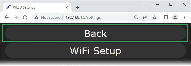
- Use your mDNS address (e.g., http://mylights.local/) to access the WLED User Interface (UI).
A Quick Tour of the WLED UI
WLED’s UI, though initially daunting, is straightforward and organized into five distinct sections.
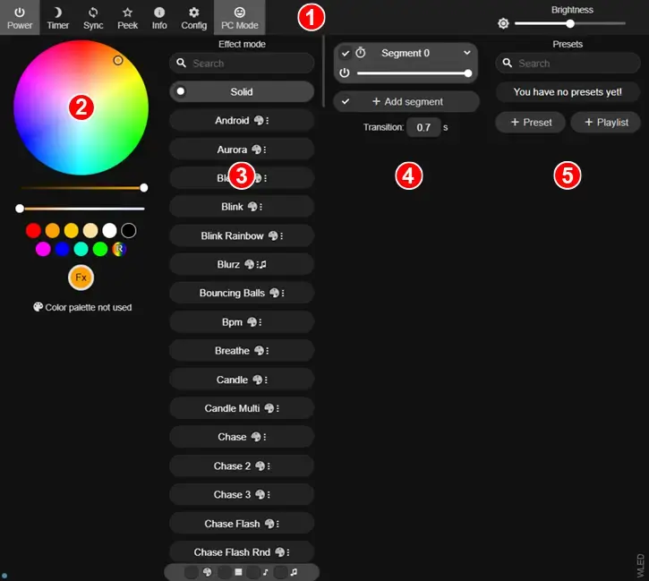
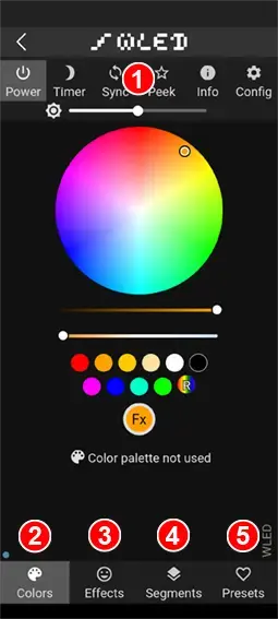
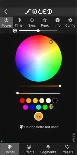
- Configuration: This section houses essential controls such as Power (for toggling lights), Timer (for scheduling light cycles), Sync (for synchronizing multiple WLED devices), Peek (for previewing animations), Config (for LED and GPIO configuration), and a Brightness slider (for adjusting overall brightness).
- Color Picker: Here, users can alter LED colors, both static and animated. Further down, a variety of color palettes can be accessed for use in effects.
- Effects/Animation: This area contains a library of pre-made animations for lights. While each effect has its own color scheme, customization is easily done in the Color Picker section.
- Segment: Ideal for extensive LED arrays or matrices, this feature enables segmentation, allowing for different colors, animations, or schemes to be assigned to each segment.
- Presets: Users can create presets for personalized light shows and playlists to cycle through available animations.
Setting Up WLED Configuration
Once the initial setup is done, it’s advisable to navigate to the configuration section.
Configuring Sound Input
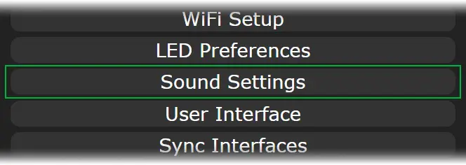
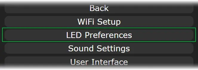
- Click on “Config” and then choose “Sound Settings.”
- Scroll down to “Sound Input Pin Manager” and adjust the “Analog input pin” number to 35. This pin serves to connect to the output pin of the MAX4466 microphone amplifier module.
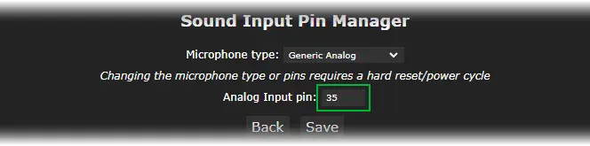
- Hit “Save.”
- Finally, click “Back” to return to the main screen.
Configuring LED lights
- Navigate to “Config” and select “LED Preferences.”
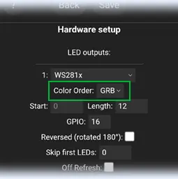
- Scroll down to “Hardware Setup” and specify the type of LED strip in use.

- Adjust the “Length” to correspond to the number of LEDs. For instance, if there are 12 LEDs in total, set the length to 12.

- Take note of the GPIO pin number, which will be used to transmit data to the LEDs. By default, GPIO16 is utilized.

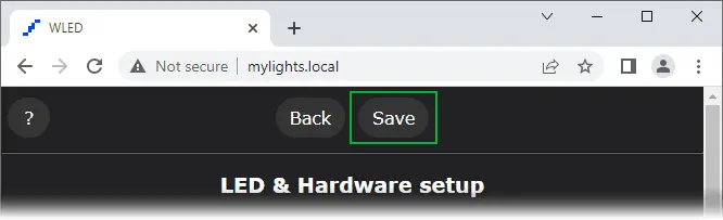
- Scroll back up and click “Save.”

- Click “Back” to return to the main screen.
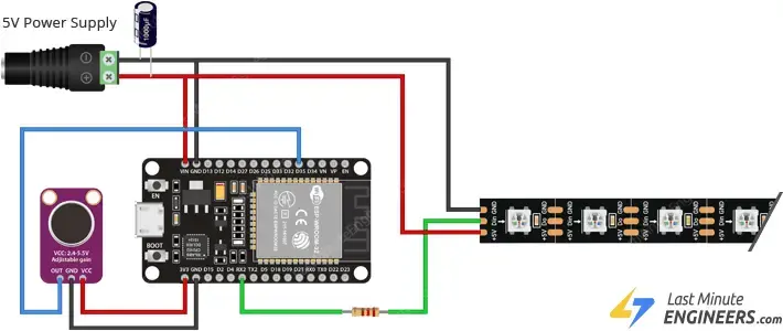
Connecting the Hardware
After configuring the WLED, disconnect the ESP32 from the USB port. Now, let’s proceed to connect the addressable LED strip and the MAX4466 module to the ESP32.
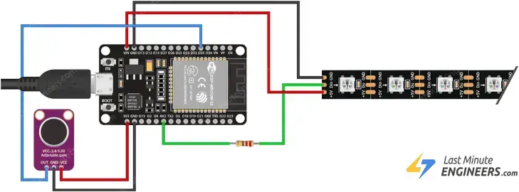
The wiring for the addressable LED strip is quite simple. You’ll need to connect only three wires: two for power and one for data transmission.
Connect the Red wire (+5V/VCC) of the addressable LED strip to the ESP32’s VIN pin, and the White/Yellow wire (GND) to the ESP32’s GND pin.
Finally, connect the Green wire (DIN) of the LED strip to the ESP32’s GPIO16 (RX2), through a 330 Ohm resistor. This resistor is placed to safeguard the data pin. A resistor ranging from 220 to 470 Ohms should suffice. Try to position the resistor as close to your addressable LEDs as possible.
Now, let’s connect the MAX4466 module to the ESP32. The VCC of the MAX4466 module can vary between 2.4-5VDC. For optimal performance, it’s recommended to utilize the 3.3V pin as it provides the most stable supply on the ESP32. Thus, connect the module’s VCC pin to the ESP32’s 3.3V pin, and the GND pin to the ground. Finally, connect the OUT pin of the module to the ESP32’s ADC pin, GPIO35.
If you have a small number of LEDs, you can power the strip directly from the ESP32 by connecting it to your computer (or a wall charger) with a USB cable.
For larger projects requiring more LEDs, USB power won’t suffice. In this case, you should supply power to the strip from an external source. Remember that each RGB LED consumes approximately 60mA (20mA per color channel) at full brightness. This means that for every 30 LEDs, your LED strip could draw up to 1.8 Amps.
Once the wiring is complete, the LEDs should illuminate and emit a soft yellow light. If this isn’t the case, double-check your wiring before proceeding.
From here, all operations can be performed via the WLED App.
Using the WLED Mobile App
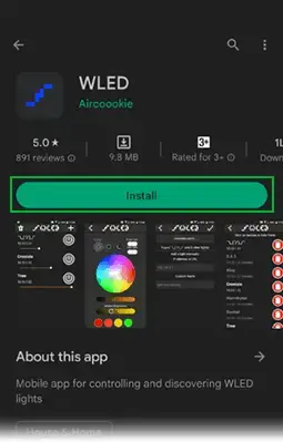
- Download the WLED app from either the Google Play Store or the Apple App Store onto your smartphone or tablet.
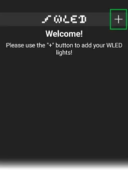
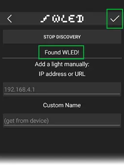
- Open the app and tap on the plus icon located in the upper right corner to access the discovery page.
- Tap on “Discover Lights.” This will initiate a search through your Wi-Fi network for all connected boards running WLED software.
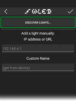
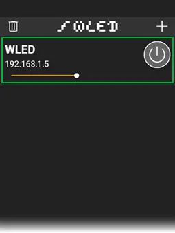
- Once the app indicates “Found WLED!” click on the tick icon situated in the upper-right corner. This action will return you to the home page, where you’ll find a list of all WLED devices on your network.
- Select the newly discovered device to open its control panel.
- Choose a color using the color wheel. And there you have it – fully operational, remotely controlled addressable LEDs!
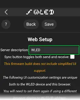
- If you have multiple WLED devices, you might want to customize the name displayed in the app for easier differentiation. Go to Config > User Interface, assign the desired name, then hit Save.
Changing Effects
WLED provides a selection of over 30 unique sound-reactive effects, unlocking the true enjoyment of the experience.
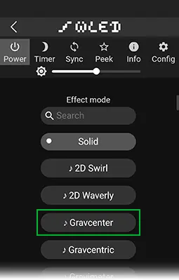
- Head to the Effects tab and opt for an effect labeled with a musical-note symbol preceding its name. The LEDs will respond instantly.
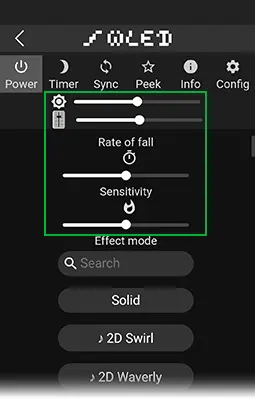
- Customize the Rate of Fall, sensitivity, and LED brightness to tailor the effects according to your preferences.
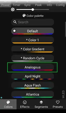
- Each effect comes with its predefined color scheme, which can be effortlessly modified in the Color Picker section. This maintains the animation effect while altering the colors.
Adjusting the Sensitivity
Depending on the sound source, adjusting the gain of the MAX4466 module might be necessary. Gain essentially determines how much the module amplifies the sound signal and, consequently, the sensitivity to sound.
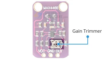
To adjust the gain, locate the small trimmer potentiometer on the back of the MAX4466 module and use a small straight-bladed screwdriver for the adjustments. The gain range can vary from 25x to 125x. Turning the potentiometer counterclockwise (CCW) increases the gain, whereas turning it clockwise (CW) decreases it.
You can also fine-tune the sound sensitivity through WLED settings to meet your specific needs. To do so, go to Config > Sound Settings.
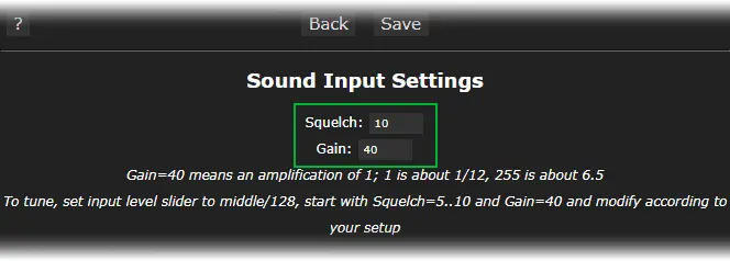
Here, you’ll encounter two settings:
- Squelch: This represents the minimum threshold at which the lights will exhibit any color or effect. Higher values necessitate louder sounds to activate the LEDs.
- Gain: This setting regulates sound sensitivity. Higher values indicate greater sensitivity.
Feel free to experiment with these settings until you achieve the optimum experience for your setup.
Related article
- ESP32 Fundamentals: Delving Into Hall Effect Sensor Technology
- Mastering Bluetooth Low Energy with ESP32 (BLE)
- Understanding ESP32 Sleep Modes for Optimal Power Usage
- Simplified ESP32 OTA Setup: Arduino IDE Web Updater Tutorial
- Unlocking ESP32 Potential: Easy OTA Programming Tutorial


