
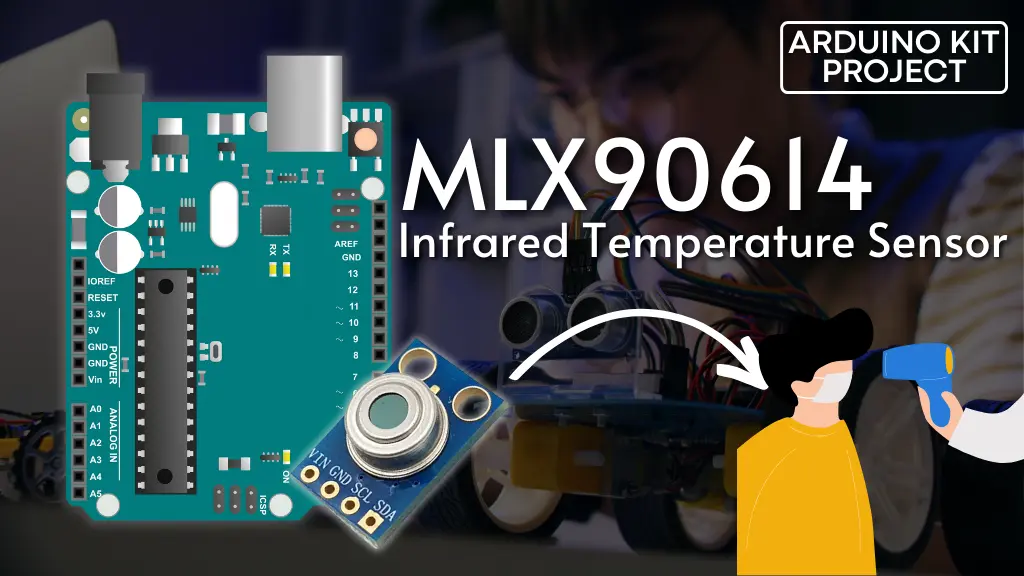
Ever since COVID-19 appeared, non-contact infrared temperature scanners have become ubiquitous worldwide, appearing in places ranging from airports to restaurants. You might find yourself intrigued by these scanners, or perhaps you’re considering building one. If so, the Melexis MLX90614 Module could be your top choice for an affordable option.
Parts Required
MLX90614 Module Hardware Overview
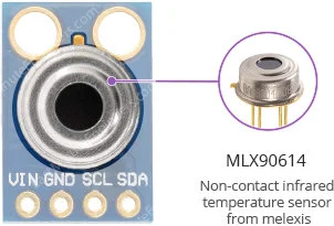
At the heart of this module is the MLX90614, a high-precision non-contact infrared temperature sensor developed by Melexis. Unlike traditional temperature sensors, this device can measure temperature without making direct contact. This feature is particularly beneficial for monitoring the temperatures of moving objects, such as rotating motor shafts or items on a conveyor belt. Simply point the sensor at the target, and it will detect the temperature by capturing emitted infrared waves.
Capabilities
The MLX90614 provides two temperature readings: object temperature and ambient temperature. Object temperature refers to the non-contact measurement detected by the sensor, while ambient temperature indicates the temperature at the sensor’s die. Although ambient temperature can be useful for data calibration, the most critical information comes from object temperature measurements.
Due to its non-contact nature, this sensor can detect a wider range of temperatures compared to most digital sensors: object temperature measurements range from -70 to 382.2°C, while ambient temperature measurements range from -40 to 125°C. Both object temperature and ambient temperature boast a resolution of 0.02°C, with a standard accuracy of 0.5°C around room temperatures.
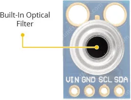
Built-In Optical Filter
The MLX90614 features a built-in optical filter that blocks visible and near-infrared light, reducing their impact on measurements. It also provides immunity against ambient light and sunlight.
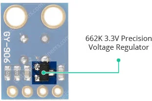
Power Requirement
Equipped with a 662K 3.3V precision voltage regulator and voltage level translator, the module ensures compatibility with your preferred 3.3V or 5V microcontroller without any complications.
During operation, the MLX90614 consumes less than 2mA, making it suitable for integration into battery-powered devices such as handheld thermal scanners.
Here are the complete specifications:
| Object temperature | -70°C to 382.2°C |
| Ambient temperature | -40°C to 85°C |
| Accuracy | ±0.5°C (around room temperatures) |
| Resolution | ±0.2°C |
| Field of view | 90° |
| Supply voltage | 3.3 to 5.5V |
| Operating Current | 2mA |
For more details, please refer below datasheet.
How Do Infrared Thermometers Work?
If you’ve ever used or observed someone using an infrared thermometer, you might have pondered, “How does this method of measurement function?”
Well, infrared thermometers, such as the MLX90614, exploit the fact that any object, including humans, emits light in the infrared spectrum—though imperceptible to the human eye—directly correlating with its temperature, as per the Stefan–Boltzmann law.
Internally, the MLX90614 consists of two elements: an infrared thermopile detector and an ASSP (Signal-Conditioning Application Processor). Below is an internal block diagram of the MLX90614 illustrating both the thermopile and the ASSP.
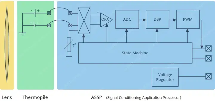
The IR radiation emitted by an object or human is initially focused by a converging (convex) lens onto a specialized infrared detector known as a Thermopile. This thermopile assesses the amount of infrared energy emitted by objects within its field-of-view (FOV), generating an electrical signal proportional to this energy.
The voltage produced by the thermopile is captured by the ASSP’s 17-bit ADC, undergoes processing, and is then relayed to the microcontroller.
The remarkable aspect is that this entire process unfolds within a fraction of a second.
Field of View (FOV)
Understanding an IR thermometer’s field-of-view (FOV) is crucial.
It’s defined by the angle within which the sensor can detect thermal radiation. This implies that the sensor captures all objects within its FOV and returns the average temperature of those objects.

It’s imperative that the object being measured completely occupies the FOV. Otherwise, the sensor might detect unintended objects, leading to inaccurate readings.

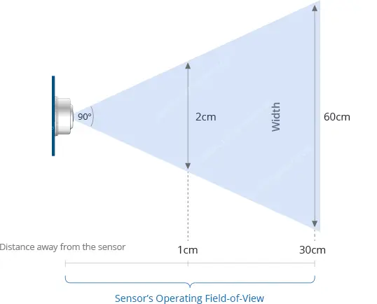
Moreover, the FOV dictates the relationship between the distance from an object and the sensing area. When the sensor is close to the object, its sensing area is narrow, but widens as the distance increases.
The MLX90614 has a cone-shaped FOV, relatively wide at 90°. This means that for every 1cm increase in distance from an object, the sensing area expands by 2cm. For instance, if you’re approximately 30cm (about 1 foot) away from an object, the sensing area will span about 60cm (about 2 feet).
MLX90614 Output Interfaces
The MLX90614 offers two interfaces, with one serving as a gateway to the other. The primary means of communication with the MLX90614 is through the 2-wire SMBus interface. Once the SMBus interface is established, you can then configure the MLX90614 to generate a PWM (pulse-width-modulated) signal representing the measured temperature.
SMBus Interface
The main interface to the MLX90614 is the 2-wire SMBus interface, essentially akin to I2C (albeit a slightly non-standard version known as “repeated-start”), utilizing the same two signals – SDA and SCL – for data and clock transmission respectively. A master device controls the clock signal, while the data signal is bidirectional.
Each MLX90614 comes with a default I2C address of 0x5A. Nonetheless, it can be programmed to assume one of 127 I2C addresses, enabling the addition of up to 127 devices on the same bus for a broader temperature mapping.
PWM Interface
The MLX90614’s data can also be accessed via the PWM interface. It’s important to note that prior configuration over the SMBus is necessary to utilize the PWM interface.
Once configured, the MLX90614 emits a continuous 10-bit PWM signal on the SDA pin, representing the measured object temperature. By default, the PWM signal covers a range from -20°C to 120°C with an output resolution of 0.14°C, but adjustments can be made via the SMBus.
Thermal Relay/Thermal Switch
By defining this range (setting minimum and maximum temperature values), the PWM output can be transformed into a “Thermal Relay/Thermal Switch” signal.
When the temperature surpasses the set threshold, the PWM pin is activated, serving as an interrupt source or directly controlling a relay. It’s worth noting that the output drive capability is limited to 25mA.
MLX90614 Module Pinout
The MLX90614 module features the following connections:
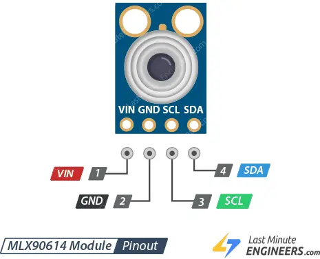
- VCC: This is the power pin. You can connect it to either the 3.3V or 5V output from your Arduino.
- GND: This is the ground connection.
- SCL: This is the I2C clock pin. Connect it to your Arduino’s I2C clock line.
- SDA: This is the I2C data pin. Connect it to your Arduino’s I2C data line.
Connecting an MLX90614 Module to an Arduino
With our module knowledge in hand, let’s proceed to link it up with our Arduino!
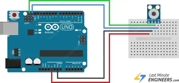
To begin, attach the VCC pin to the power supply, preferably 5V. Ensure it aligns with the voltage of your microcontroller logic. Typically, for most Arduinos, this is 5V. However, for devices with 3.3V logic, opt for 3.3V. Then, establish a connection between GND and the common ground.
Next, link the SCL pin to the I2C clock pin and the SDA pin to the I2C data pin on your Arduino. Keep in mind that each Arduino Board possesses distinct I2C pins, so ensure proper alignment. In Arduino boards with the R3 layout, the SDA (data line) and SCL (clock line) are situated on the pin headers near the AREF pin, also identified as A5 (SCL) and A4 (SDA).
Refer to the following illustration for the wiring setup.
Library Installation
Multiple libraries are accessible for the MLX90614 sensor. However, in this example, we’re utilizing the Adafruit library due to its user-friendly nature, albeit it only supports basic temperature measurement and lacks the advanced features of the sensor. You can obtain the library directly from the Arduino IDE Library Manager.
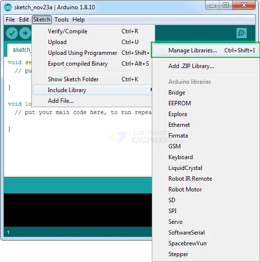
To install the library, navigate to Sketch > Include Library > Manage Libraries… Wait for the Library Manager to download the libraries index and update the list of installed libraries.
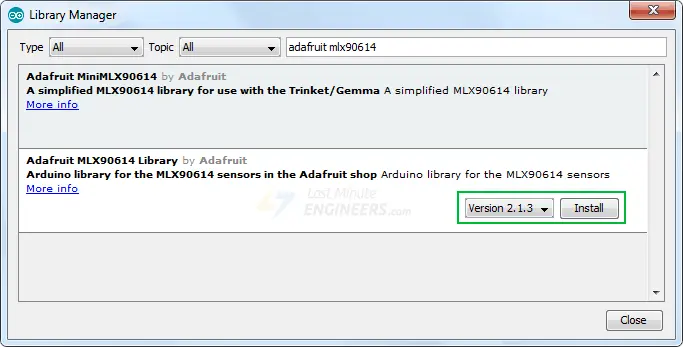
Filter your search by typing ‘adafruit mlx90614’. Select the entry, then click Install.
Arduino Code
Below is a simple Arduino sketch enabling you to promptly test the functionality of the MLX90614. Upload it to your Arduino and observe the ambient and object temperature readings printed on the serial interface.
#include <Adafruit_MLX90614.h>

Adafruit_MLX90614 mlx = Adafruit_MLX90614();

void setup() {
	Serial.begin(9600);
	while (!Serial);

	if (!mlx.begin()) {
		Serial.println("Error connecting to MLX sensor. Check wiring.");
		while (1);
	};
}

void loop() {
	Serial.print("Ambient = "); Serial.print(mlx.readAmbientTempC());
	Serial.print("*C\tObject = "); Serial.print(mlx.readObjectTempC()); Serial.println("*C");
	Serial.print("Ambient = "); Serial.print(mlx.readAmbientTempF());
	Serial.print("*F\tObject = "); Serial.print(mlx.readObjectTempF()); Serial.println("*F");

	Serial.println();
	delay(500);
}
Once the sketch is uploaded, open your serial monitor, setting the baud rate to 9600 bps. You should observe both the ambient temperature and the object temperature being displayed.
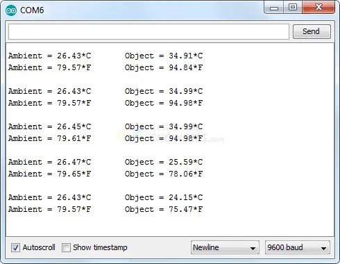
Experiment by pointing the sensor at objects around you or towards your forehead to ensure you’re not running a fever!
Code Explanation:
The sketch begins by including the Adafruit_MLX90614 library. Within the same global scope, an Adafruit_MLX90614 object named mlx is instantiated.
#include <Adafruit_MLX90614.h>

Adafruit_MLX90614 mlx = Adafruit_MLX90614();
In the setup function, we initialize the serial communication with the PC and invoke the begin() function.
The begin() function initializes the I2C interface. While this function can optionally take a parameter (the 7-bit address of your sensor), if left empty, it assumes the address is set to the default (0x5A).
void setup() {
	Serial.begin(9600);
	while (!Serial);

	if (!mlx.begin()) {
		Serial.println("Error connecting to MLX sensor. Check wiring.");
		while (1);
	};
}
Within the loop function, we simply print the current ambient and object temperatures using the readAmbientTempC()/mlx.readAmbientTempF() and readObjectTempC()/readObjectTempF() functions.
void loop() {
	Serial.print("Ambient = "); Serial.print(mlx.readAmbientTempC());
	Serial.print("*C\tObject = "); Serial.print(mlx.readObjectTempC()); Serial.println("*C");
	Serial.print("Ambient = "); Serial.print(mlx.readAmbientTempF());
	Serial.print("*F\tObject = "); Serial.print(mlx.readObjectTempF()); Serial.println("*F");

	Serial.println();
	delay(500);
}
Related article
- DIY Project: Arduino Interface for TFMini-S LiDAR Sensor
- Understanding Accelerometers: Interface ADXL335 with Arduino
- Arduino Soil NPK Sensor: Maximizing Plant Nutrition
- Step-by-Step: Connecting Reed Switch to Arduino
- Track Heart Rate: A Guide to Pulse Sensor and Arduino Integration
- Using TMP36 Temperature Sensor: Arduino Interfacing Guide


