

A Hall sensor, also known as a Hall effect sensor, is a type of device that detects the presence and intensity of a magnetic field through the Hall effect. It finds widespread use in various applications including proximity sensing, positional tracking, speed measurement, and current sensing.
These sensors are incredibly affordable, often available in bulk for minimal cost. Even though integrating such a low-cost sensor with a feature-rich WiFi-enabled microcontroller like the ESP32 might initially seem unnecessary, it opens up possibilities for future projects. For instance, one could envision utilizing it for a WiFi-enabled door status sensor. This illustrates the potential for innovative applications.
Now, let’s delve into understanding how to interface with the Hall sensor on the ESP32. However, before we proceed, let’s review the fundamental principles behind Hall-effect sensors.
Parts Required
| Component Name | Buy Now |
| ESP32-WROOM-32 Development | Amazon |
How Hall-effect Sensors Work?
The operation of a Hall-effect sensor is based on the discovery of the Hall effect by Edwin Hall in 1879. The principle is straightforward:
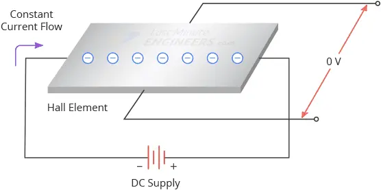
Imagine a conductive sheet resembling a dollar bill. When a constant voltage is applied across its left and right sides, electrons flow through the sheet in a straight line. In the absence of any magnetic field, measuring the voltage across the top and bottom of the sheet would yield nearly zero.
However, when a magnetic field is introduced perpendicular to the current flow, the Lorentz force acts upon the electrons, causing them to veer from their original path. Consequently, electrons accumulate on one side of the sheet while becoming sparse on the other. This discrepancy in electron distribution creates a potential difference, known as the Hall voltage, across the sheet—a phenomenon referred to as the Hall effect.
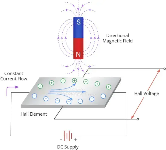
The magnitude of the Hall voltage increases with a stronger magnetic field, as well as with a higher current flow, since more electrons are available for deflection. In essence, the Hall voltage is directly proportional to both the electric current in the conductor and the intensity of the magnetic field.
Therefore, by measuring the Hall voltage at a known current, one can ascertain the strength of the magnetic field.
ESP32 Hall Effect Sensor
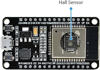
Built into the ESP32 is a Hall effect sensor, situated underneath the metal cover of the ESP32-WROOM-32 module.
Its integration into the ESP32 enables effortless linking of sensor data with WiFi or Bluetooth functionalities, streamlining tasks related to remote monitoring and control.
While the onboard Hall sensor may not completely replace specialized external sensors for precise applications due to its location and sensitivity, it still offers a plethora of potential uses. These range from simple detection of magnetic fields to triggering specific actions when a magnet is nearby, or even creating basic educational projects to illustrate the Hall effect.
Reading the Hall Sensor
To read the Hall sensor on the ESP32 is simple. In the Arduino IDE, you utilize the hallRead() function. This function provides an integer value representing the Hall voltage.
hallRead();
Example Code
Let’s explore reading the hall sensor through an example provided by the library. Begin by opening your Arduino IDE and navigating to File > Examples > ESP32, then open the HallSensor sketch.
This example straightforwardly reads the internal hall sensor on the ESP32 and displays the result on the serial monitor.
int val = 0;
void setup() {
  Serial.begin(9600);
}

void loop() {
  // put your main code here, to run repeatedly:
  val = hallRead();
  // print the results to the serial monitor:
  //Serial.print("sensor = ");
  Serial.println(val);//to graph
}
Once you’ve uploaded the sketch, open the serial monitor at baud rate 9600 and press the EN button on the ESP32.
Now, experiment by bringing a magnet close to the ESP32 chip. You’ll observe that the readings change based on the distance and polarity of the magnet.
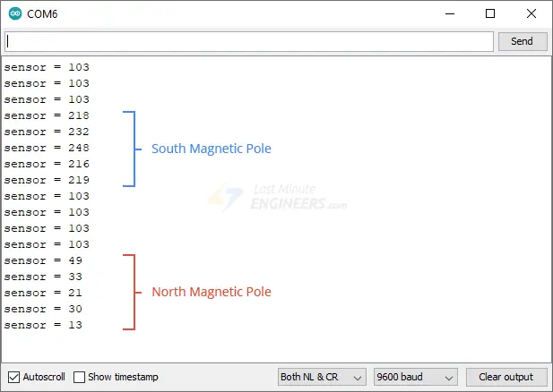
Visualizing the signal in the Serial Plotter will aid in understanding: when no magnetic field is detected, the output remains at approximately 100. If the south pole of a magnet is brought near, the output increases toward 200, and if the north pole of a magnet is brought close, the output decreases toward 0.
Related article
- Learn DC Motor Control with ESP32 and L298N Driver
- Step-by-Step Guide: ESP32 Servo Motor Control via Web Server
- Distance Measurement with ESP32: HC-SR04 Ultrasonic Sensor Guide
- ESP32 Essentials: Exploring the Power of Bluetooth Classic
- Exploring ESP32 PWM: Your Complete Starter’s Guide to PWM Signals


