
If you’ve dabbled with Arduino previously, you’re accustomed to how straightforward it is to produce a PWM signal using the analogWrite() function—simply specify the pin and duty cycle, and you’re set.
However, with the ESP32, it’s akin to leveling up in a game. We gain more controls (hooray!), but we also need to handle them judiciously (which adds a bit of complexity). The ESP32 requires us to specify a few additional parameters, such as the PWM frequency, resolution, channel selection, as well as the duty cycle and pin assignment. It might seem daunting, but fear not!
This guide will comprehensively cover PWM on the ESP32, from fundamental concepts to practical demonstrations.
ESP32 PWM Pins
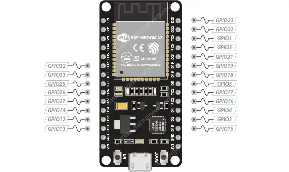
PWM output is accessible on all GPIO pins of the ESP32, with the exception of four GPIO pins dedicated solely for input. The following GPIOs have the capability to support PWM:
PWM on ESP32
The ESP32 provides two PWM peripherals: the LED Control Peripheral (LEDC) and the Motor Control Pulse Width Modulator Peripheral (MCPWM).
The MCPWM peripheral is primarily designed for motor control and comes with additional features such as a dead zone and auto-braking. In contrast, the LEDC peripheral is specifically tailored for LED driving, boasting features like auto-dimming and other advanced functionalities. Nonetheless, it can also be employed for generating PWM signals for various other applications.
This tutorial will mainly concentrate on the LEDC peripheral.
PWM Frequency
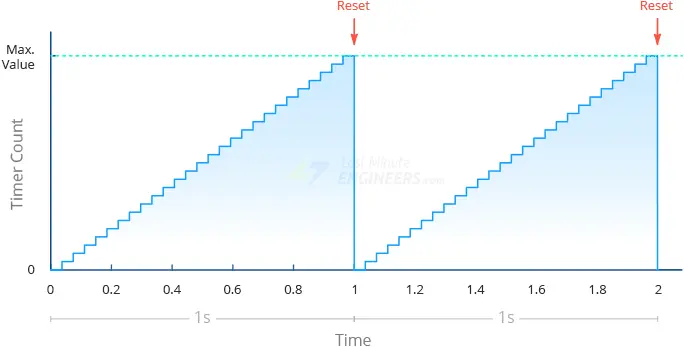
Similar to most PWM controllers, the LEDC peripheral on the ESP32 utilizes a timer for generating PWM signals.
Visualize the timer as continually counting up until it reaches its maximum value, after which it resets to zero, starting the next counting cycle. The interval between these resets, representing the PWM frequency, is measured in Hertz (Hz). For instance, setting a frequency of 1 Hz implies that the timer takes 1 second to complete one counting cycle from 0 to the maximum value before restarting. Conversely, a frequency of 1000 Hz indicates that the timer completes one cycle in just 1 millisecond.
The ESP32 is capable of generating PWM signals with frequencies of up to 40 MHz.
Duty Cycle
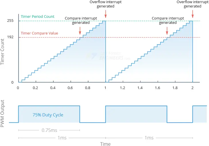
Next, let’s define the Duty Cycle of the PWM output. The duty cycle indicates how many timer ticks the PWM output remains high before going low. This value is stored in the timer’s capture/compare register (CCR).
Upon timer reset, the PWM output goes high. As the timer progresses and reaches the value stored in the capture/compare register, the PWM output transitions to low. However, the timer continues counting. When the timer reaches its maximum value, the PWM output returns high, and the timer resets to begin counting for the next period.
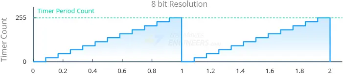
For example, suppose we aim to generate a PWM signal with a frequency of 1000 Hz, an 8-bit resolution, and a 75% duty cycle. With an 8-bit resolution, the timer’s maximum value is 255 (28-1). Considering the 1000 Hz frequency, the timer takes 1 millisecond (0.001 seconds) to count from 0 to 255. With a 75% duty cycle, the value 256 * 75% = 192 will be stored in the capture/compare register. Consequently, when the timer resets, the PWM output goes high. It remains high until the counter reaches 192, at which point it switches to low. As the timer reaches 255, the PWM output toggles back to high, and the timer resets to start counting for the subsequent period.
PWM Resolution
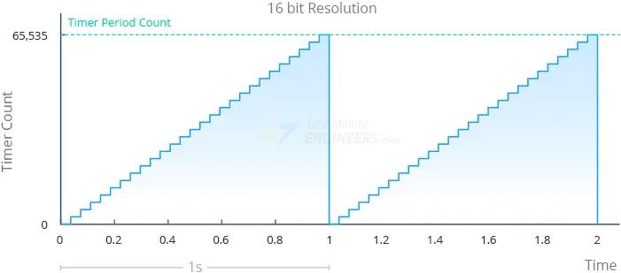
What determines the “maximum” value precisely? This value is determined by the PWM Resolution. If the PWM resolution is “n” bits, the timer counts from 0 to 2n-1 before resetting. For instance, when we set the timer with a frequency of 1 Hz and a resolution of 8 bits, it takes 1 second for the timer to count from 0 to 255 (28). Similarly, with a frequency of 1 Hz and a resolution of 16 bits, it still takes 1 second for the timer to count, but this time from 0 to 65,535 (216).
It’s crucial to understand that a higher resolution means more “timer increments” within the same specified time period, resulting in increased “granularity” in timings.
The ESP32’s PWM resolution can be adjusted from 1 to 16 bits. This flexibility allows the duty cycle to be set at up to 65,536 (216) different levels. This level of control is essential for tasks such as adjusting LED brightness or controlling motor speeds precisely.
PWM Channels
Now, let’s focus on the concept of a channel, which represents a unique PWM output signal.
The ESP32 features 16 channels, allowing it to generate 16 distinct PWM waveforms. These channels are split into two groups: 8 high-speed channels and 8 low-speed channels.
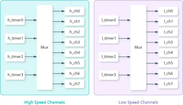
High-speed channels are hardware-implemented, enabling automatic and glitch-free adjustments to the PWM duty cycle. Conversely, low-speed channels lack these capabilities and depend on software for duty cycle changes.
Within each group, 4 timers are shared among 8 channels, meaning every two channels share the same timer. Since the timer determines the frequency, it’s important to note that the frequency of each channel within a pair cannot be adjusted independently. However, the PWM duty cycle of each channel can be controlled independently.
In summary, an ESP32 boasts 16 PWM channels capable of operating at eight distinct frequencies, with each channel supporting a different duty cycle.
To generate a PWM signal on a specific pin, you “attach” that pin to a channel. This linkage instructs the ESP32 to output the PWM waveform generated by the channel on the designated pin. Multiple pins can be attached to the same channel, allowing them all to produce the same PWM signal. While all GPIO pins support PWM output, the ESP32 only has 16 channels, limiting the number of simultaneous PWM waveforms to 16. This doesn’t restrict the number of pins capable of outputting PWM signals, but it does limit the variety of simultaneous signals.
In practical terms, if you want a set of LEDs to blink in perfect synchronization, you can set up a single channel with a specific frequency and duty cycle, then attach all relevant pins (connected to the LEDs) to this channel. However, when dealing with servos, particularly in scenarios like a robotic arm where each joint (servo) requires independent control, assigning different pins to different channels proves advantageous.
Selecting PWM Frequency and Resolution
The ESP32 is capable of producing a PWM signal with a frequency of up to 40 MHz, and the PWM resolution can be adjusted from 1 to 16 bits. However, it’s important to note that you cannot simultaneously set a frequency of 40 MHz and a resolution of 16 bits. This limitation arises because both the maximum PWM frequency and resolution are constrained by the clock source.
To illustrate, imagine a clock (whether it’s a CPU clock or a timer) operating at a frequency of 40 MHz. In this scenario, the highest achievable PWM frequency is also 40 MHz. We cannot generate a PWM waveform faster than our clock permits.
What about resolution? Resolution refers to how finely we can divide one period of the PWM waveform into different duty cycles. The key insight here is that dividing the PWM waveform requires a CPU clock running at PWM_freq * 2PWM_resolution. This is because creating those duty cycles necessitates the ability to create those time slices.
From this, two crucial points emerge:
- PWM_freq * 2PWM_resolution cannot surpass the clock speed.
- PWM frequency and resolution are interconnected. Higher PWM frequency leads to lower duty cycle resolution, and vice versa.
According to Espressif documentation, the LEDC low-speed timer clock source is an 80 MHz APB clock. As a rule of thumb, it’s advisable to keep PWM_freq * 2PWM_resolution below 80 MHz.
Furthermore, Espressif documentation provides examples to support this:
- A PWM frequency of 5 kHz can have a maximum duty resolution of 13 bits, resulting in a resolution of approximately 0.012%, or 213=8192 discrete levels.
- A PWM frequency of 20 MHz can have a maximum duty resolution of 2 bits, resulting in a resolution of 25%, or 22=4 discrete levels.
- A PWM frequency of 40 MHz can only accommodate a duty resolution of 1 bit, meaning the duty cycle remains fixed at 50% and cannot be adjusted.
If this seems overwhelming, consider this: The Arduino Uno offers a ~490 Hz PWM waveform at 8 bits, more than sufficient for smoothly fading an LED. Hence, you can start with a frequency of 500 Hz and 8-bit resolution, and then experiment as needed.
Generating PWM signal with the LEDC Library
Let’s dive right in! The ESP32 Arduino core comes equipped with the LEDC Library, simplifying the management of Pulse Width Modulation (PWM) on the ESP32. Although initially tailored for LED control, the LEDC library proves versatile for various applications requiring PWM waveforms, including piezo speaker ‘music’ emission and motor driving.
Below are the steps to utilize the LEDC library for generating a PWM signal with the ESP32 using the Arduino IDE:
- Select a PWM Channel: Choose from 16 available channels, numbered 0 to 15.
- Determine the PWM Frequency: It can range up to 40 MHz, but for our LED fading demonstration, a frequency of 500 Hz should suffice.
- Determine the PWM Resolution: It spans from 1 to 16 bits. The number of discrete duty cycle levels is determined by 2resolution. For instance, setting the resolution to 8 bits yields 256 discrete duty cycle levels [0–255]. Conversely, a resolution of 16 bits provides 65,536 discrete duty cycle levels [0–65535].
- Choose the GPIO Pin(s): Select one or more GPIO pins on the ESP32 to output the PWM signal.
- Configure the PWM Channel: Utilize the ledcSetup(channel, freq, resolution) function to configure the chosen PWM channel with the selected frequency and resolution.
- Attach the Pin(s) to the Channel: Employ the ledcAttachPin(pin, channel) function to attach the selected pin(s) to the designated channel.
- Set the Duty Cycle: Lastly, set the actual duty cycle value for a given channel using the ledcWrite(channel, dutycycle) function.
Example 1 – Fading an LED
Here’s a brief example sketch demonstrating how to fade an LED, ideal for showcasing PWM generation on the ESP32.
Wiring
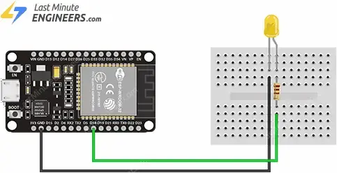
The wiring setup is straightforward. Place an LED and a 330 Ω current-limiting resistor on the breadboard as depicted in the figure below. Connect the longer leg of the LED (the anode) to pin GP18 through the 330 Ω resistor, and connect the shorter leg to the ground pin of your ESP32.
Code
Copy the code provided below into your Arduino IDE.
const int PWM_CHANNEL = 0;    // ESP32 has 16 channels which can generate 16 independent waveforms
const int PWM_FREQ = 500;     // Recall that Arduino Uno is ~490 Hz. Official ESP32 example uses 5,000Hz
const int PWM_RESOLUTION = 8; // We'll use same resolution as Uno (8 bits, 0-255) but ESP32 can go up to 16 bits

// The max duty cycle value based on PWM resolution (will be 255 if resolution is 8 bits)
const int MAX_DUTY_CYCLE = (int)(pow(2, PWM_RESOLUTION) - 1);

const int LED_OUTPUT_PIN = 18;

const int DELAY_MS = 4;  // delay between fade increments

void setup() {

  // Sets up a channel (0-15), a PWM duty cycle frequency, and a PWM resolution (1 - 16 bits)
  // ledcSetup(uint8_t channel, double freq, uint8_t resolution_bits);
  ledcSetup(PWM_CHANNEL, PWM_FREQ, PWM_RESOLUTION);

  // ledcAttachPin(uint8_t pin, uint8_t channel);
  ledcAttachPin(LED_OUTPUT_PIN, PWM_CHANNEL);
}

void loop() {

  // fade up PWM on given channel
  for(int dutyCycle = 0; dutyCycle <= MAX_DUTY_CYCLE; dutyCycle++){
    ledcWrite(PWM_CHANNEL, dutyCycle);
    delay(DELAY_MS);
  }

  // fade down PWM on given channel
  for(int dutyCycle = MAX_DUTY_CYCLE; dutyCycle >= 0; dutyCycle--){
    ledcWrite(PWM_CHANNEL, dutyCycle);
    delay(DELAY_MS);
  }
}
Testing the Example
Now, upload the code to your ESP32. You’ll witness the LED’s brightness smoothly transitioning from completely off to fully illuminated and back again.
Code Explanation:
At the beginning of the sketch, several constants are defined to configure the PWM characteristics. Initially, the constant PWM_CHANNEL is set to 0. The ESP32 supports 16 channels (numbered 0 to 15), each capable of generating independent waveforms.
Subsequently, PWM_FREQ is defined and set to 500, representing the frequency of our PWM signal. Notably, this is similar to the Arduino Uno’s ~490 Hz, sufficient for smoothly fading an LED.
Next, PWM_RESOLUTION is established as 8, indicating the resolution (in bits) of the PWM signal. While we’re utilizing 8 bits (akin to the Arduino Uno), the ESP32 can extend up to 16 bits.
const int PWM_CHANNEL = 0;
const int PWM_FREQ = 500;
const int PWM_RESOLUTION = 8;
MAX_DUTY_CYCLE is then calculated using the formula 2^PWM_RESOLUTION – 1. This value determines the maximum achievable duty cycle based on the chosen resolution.
const int MAX_DUTY_CYCLE = (int)(pow(2, PWM_RESOLUTION) - 1);
Following this, LED_OUTPUT_PIN is set to 18, representing the GPIO pin on the ESP32 to which the LED is connected.
Lastly, DELAY_MS is defined and set to 4, serving as the delay (in milliseconds) between increments to control the LED’s fading speed.
const int LED_OUTPUT_PIN = 18;
const int DELAY_MS = 4;
During setup, the ledcSetup() function is invoked to configure the PWM properties using the previously defined constants. This function requires three arguments: the PWM channel, frequency, and resolution.
ledcSetup(PWM_CHANNEL, PWM_FREQ, PWM_RESOLUTION);
Subsequently, the ledcAttachPin() function is employed to attach the GPIO pin to the PWM channel responsible for generating the PWM signal. In this case, the PWM signal generated by PWM_CHANNEL (channel 0) will appear on LED_OUTPUT_PIN (GPIO 16).
ledcAttachPin(LED_OUTPUT_PIN, PWM_CHANNEL);
In the loop, the first for loop incrementally increases the duty cycle from 0 to its maximum value (MAX_DUTY_CYCLE), gradually brightening the LED.
for(int dutyCycle = 0; dutyCycle <= MAX_DUTY_CYCLE; dutyCycle++){
  ledcWrite(PWM_CHANNEL, dutyCycle);
  delay(DELAY_MS);
}
The second for loop decrements the duty cycle from MAX_DUTY_CYCLE to 0, gradually dimming the LED.
for(int dutyCycle = MAX_DUTY_CYCLE; dutyCycle >= 0; dutyCycle--){
  ledcWrite(PWM_CHANNEL, dutyCycle);
  delay(DELAY_MS);
}
In both for loops, the ledcWrite() function is utilized to set the LED’s brightness. This function accepts the channel generating the signal and the duty cycle as arguments.
ledcWrite(ledChannel, dutyCycle);
Example 2 – Same PWM Signal on Multiple GPIOs
It’s possible to replicate the same PWM signal across multiple GPIOs simultaneously. To achieve this, you only need to attach those GPIOs to the same channel.
Wiring
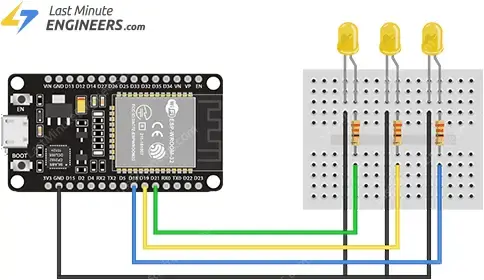
Include two additional LEDs in your circuit following the same method as the first one. Connect them to GPIO 19 and 21.
Refer to the image below for the connection setup.
Code
Now, let’s adjust the previous example to fade three LEDs using the identical PWM signal from the same channel.
const int PWM_CHANNEL = 0;    // ESP32 has 16 channels which can generate 16 independent waveforms
const int PWM_FREQ = 500;     // Recall that Arduino Uno is ~490 Hz. Official ESP32 example uses 5,000Hz
const int PWM_RESOLUTION = 8; // We'll use same resolution as Uno (8 bits, 0-255) but ESP32 can go up to 16 bits

// The max duty cycle value based on PWM resolution (will be 255 if resolution is 8 bits)
const int MAX_DUTY_CYCLE = (int)(pow(2, PWM_RESOLUTION) - 1);

const int LED_1_OUTPUT_PIN = 18;
const int LED_2_OUTPUT_PIN = 19;
const int LED_3_OUTPUT_PIN = 21;

const int DELAY_MS = 4;  // delay between fade increments

void setup() {

  // Sets up a channel (0-15), a PWM duty cycle frequency, and a PWM resolution (1 - 16 bits)
  // ledcSetup(uint8_t channel, double freq, uint8_t resolution_bits);
  ledcSetup(PWM_CHANNEL, PWM_FREQ, PWM_RESOLUTION);

  // ledcAttachPin(uint8_t pin, uint8_t channel);
  ledcAttachPin(LED_1_OUTPUT_PIN, PWM_CHANNEL);
  ledcAttachPin(LED_2_OUTPUT_PIN, PWM_CHANNEL);
  ledcAttachPin(LED_3_OUTPUT_PIN, PWM_CHANNEL);
}

void loop() {

  // fade up PWM on given channel
  for(int dutyCycle = 0; dutyCycle <= MAX_DUTY_CYCLE; dutyCycle++){
    ledcWrite(PWM_CHANNEL, dutyCycle);
    delay(DELAY_MS);
  }

  // fade down PWM on given channel
  for(int dutyCycle = MAX_DUTY_CYCLE; dutyCycle >= 0; dutyCycle--){
    ledcWrite(PWM_CHANNEL, dutyCycle);
    delay(DELAY_MS);
  }
}
Testing the Example
Now, upload the code to your ESP32. You’ll observe all three LEDs fading simultaneously, as all GPIOs are outputting the same PWM signal.
Code Explanation:
Comparing this sketch to the previous one, you’ll notice they are quite similar, with just a few distinctions. Let’s examine these variances.
In the global section, three additional constants named LED_1_OUTPUT_PIN, LED_2_OUTPUT_PIN, and LED_3_OUTPUT_PIN are defined and assigned values 18, 19, and 21 respectively. This indicates that we are working with three distinct LEDs, each connected to its own GPIO pin on the ESP32.
const int LED_1_OUTPUT_PIN = 18;
const int LED_2_OUTPUT_PIN = 19;
const int LED_3_OUTPUT_PIN = 21;
Subsequently, in the setup, the ledcAttachPin() function is invoked thrice instead of once, as seen in the preceding code. Each function call attaches a different GPIO pin (LED_1_OUTPUT_PIN, LED_2_OUTPUT_PIN, LED_3_OUTPUT_PIN) to the same PWM channel (PWM_CHANNEL), ensuring the same PWM signal is emitted to all three LEDs.
ledcAttachPin(LED_1_OUTPUT_PIN, PWM_CHANNEL);
ledcAttachPin(LED_2_OUTPUT_PIN, PWM_CHANNEL);
ledcAttachPin(LED_3_OUTPUT_PIN, PWM_CHANNEL);
It’s noteworthy that despite the inclusion of additional LEDs, there’s no alteration to the loop() function. This is because the same PWM channel governs all LEDs.
Example 3 – Fading an LED using the Potentiometer
This example demonstrates how to fade an LED using a potentiometer.
Wiring
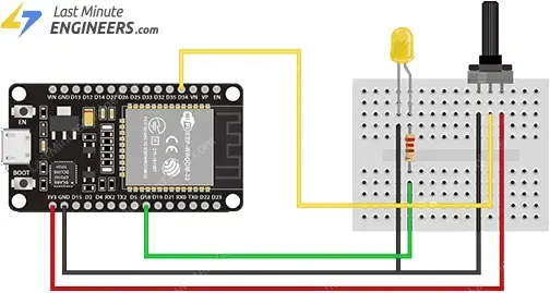
Remove the additional LEDs from your circuit and introduce a potentiometer instead. Connect one outer pin of the potentiometer to 3.3V, the opposite outer pin to GND, and its middle pin (wiper) to GPIO 34.
Refer to the image below for the wiring setup.
Code
const int PWM_CHANNEL = 0;    // ESP32 has 16 channels which can generate 16 independent waveforms
const int PWM_FREQ = 500;     // Recall that Arduino Uno is ~490 Hz. Official ESP32 example uses 5,000Hz
const int PWM_RESOLUTION = 8; // We'll use same resolution as Uno (8 bits, 0-255) but ESP32 can go up to 16 bits

// The max duty cycle value based on PWM resolution (will be 255 if resolution is 8 bits)
const int MAX_DUTY_CYCLE = (int)(pow(2, PWM_RESOLUTION) - 1);

const int LED_OUTPUT_PIN = 18;
const int POT_PIN = 34;

const int DELAY_MS = 100;  // delay between fade increments

void setup() {

  // Sets up a channel (0-15), a PWM duty cycle frequency, and a PWM resolution (1 - 16 bits)
  // ledcSetup(uint8_t channel, double freq, uint8_t resolution_bits);
  ledcSetup(PWM_CHANNEL, PWM_FREQ, PWM_RESOLUTION);

  // ledcAttachPin(uint8_t pin, uint8_t channel);
  ledcAttachPin(LED_OUTPUT_PIN, PWM_CHANNEL);
}

void loop() {
  int dutyCycle = analogRead(POT_PIN);
  dutyCycle = map(dutyCycle, 0, 4095, 0, MAX_DUTY_CYCLE);
  ledcWrite(PWM_CHANNEL, dutyCycle);

  delay(DELAY_MS);
}
Testing the Example
Now, try turning the potentiometer all the way in one direction, then all the way in the other. Observe the LED; this time, you’ll notice the LED’s brightness smoothly transitioning from completely off at one end of the potentiometer knob’s limit to fully illuminated at the other end.
Code Explanation:
Once again, there are only a few disparities between this sketch and the initial one. Let’s examine these differences.
An additional constant named POT_PIN is introduced in the global section. It is assigned the value 34, indicating that the potentiometer is linked to GPIO 34 on the ESP32 and will be utilized to dynamically determine the duty cycle, hence adjusting the LED brightness.
const int POT_PIN = 34;
Subsequently, in the loop, instead of utilizing for loops to gradually adjust the LED’s brightness, a function analogRead(POT_PIN) is invoked to obtain a raw reading from the potentiometer.
int dutyCycle = analogRead(POT_PIN);
The potentiometer reading, ranging from 0 to 4095, is then mapped to a new range spanning from 0 to MAX_DUTY_CYCLE using the map() function. This mapping aligns the potentiometer values with the permissible duty cycle values of the PWM signal, ensuring that the LED brightness can be altered across its entire range.
dutyCycle = map(dutyCycle, 0, 4095, 0, MAX_DUTY_CYCLE);
Finally, the ledcWrite() function utilizes this mapped value and applies it directly to the PWM signal, dynamically adjusting the LED brightness based on the potentiometer’s position in real-time.
ledcWrite(PWM_CHANNEL, dutyCycle);
Related article
- Learn DC Motor Control with ESP32 and L298N Driver
- Step-by-Step Guide: ESP32 Servo Motor Control via Web Server
- Distance Measurement with ESP32: HC-SR04 Ultrasonic Sensor Guide
- ESP32 Essentials: Exploring the Power of Bluetooth Classic


