

One of the standout features of ESP32 is its capability for wireless firmware updates. This type of programming is known as “Over-The-Air” (OTA).
Parts Required
| Component Name | Buy Now |
| ESP32-WROOM-32 Development | Amazon |
What exactly is OTA programming in ESP32?
OTA programming allows you to update or upload a new program to the ESP32 via Wi-Fi, eliminating the need to physically connect the ESP32 to a computer via USB.
The OTA functionality proves invaluable when physical access to the ESP module is unavailable. Furthermore, it streamlines the time required for updating each ESP module during maintenance.
A significant advantage of OTA is its ability for a single central location to send updates to multiple ESPs on the same network.
The only drawback is that you must include OTA code with each sketch you upload in order to utilize OTA in subsequent updates.
Ways To Implement OTA In ESP32
There are two methods to integrate OTA functionality into the ESP32.
- Basic OTA – updates are transmitted using the Arduino IDE.
- Web Updater OTA – updates are delivered through a web browser.
Each method offers distinct advantages, allowing you to choose the one that best suits your project requirements.
This guide will lead you through the implementation process of Basic OTA. For further insight into web updater OTA, please refer to a separate tutorial.
3 Simple Steps for Using Basic OTA with the ESP32
- Installation of Python 2.7.x series: Begin by installing the Python 2.7.x series on your computer.
- Serial Uploading of Basic OTA Firmware: Upload the sketch containing the OTA firmware serially. This initial step is necessary for subsequent over-the-air updates.
- Over-The-Air Upload of New Sketches: You can now upload new sketches to the ESP32 from the Arduino IDE wirelessly, utilizing the OTA capability.
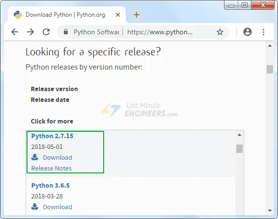
Step 1: Install Python 2.7.x series
To utilize OTA functionality, Python 2.7.x must be installed on your system if it’s not already present. You can download Python 2.7.x for Windows (MSI installer) from the official Python website.
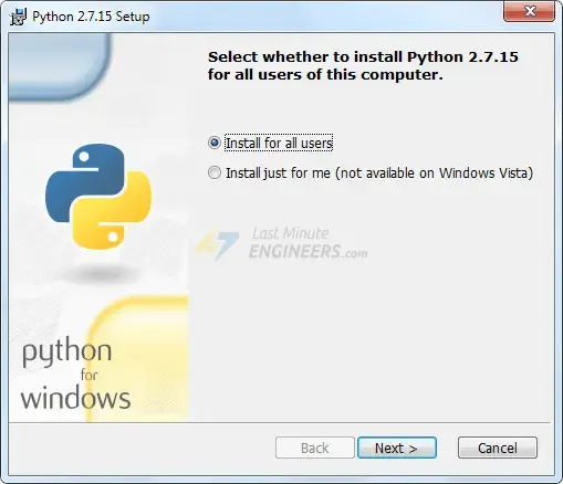
Proceed by launching the installer and following the instructions provided by the installation wizard.
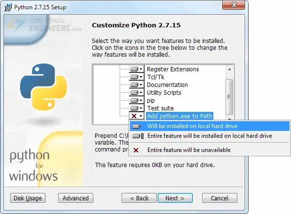
Ensure that the “Add python.exe to Path” option is checked in the Customize Python 2.7.x section.
Step 2: Upload Basic OTA Firmware Serially
As the ESP32’s factory image doesn’t include OTA Upgrade capability, you need to initially load the OTA firmware onto the ESP32 through the serial interface.
Updating the firmware beforehand is essential for performing subsequent over-the-air updates.
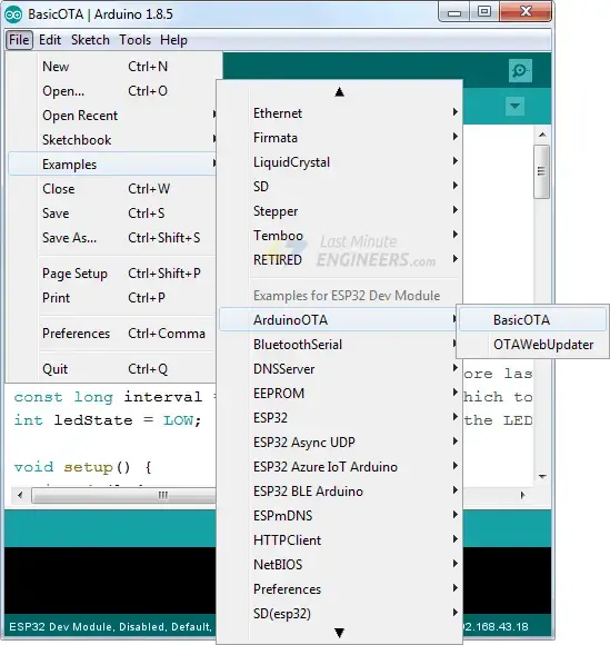
The ESP32 add-on for the Arduino IDE provides an OTA library and a BasicOTA example. Simply navigate to File > Examples > ArduinoOTA > BasicOTA.
Before uploading the sketch, modify the two variables with your network credentials to allow the ESP32 to connect to an existing network.
const char* ssid = "..........";
const char* password = "..........";
Once done, proceed with uploading the sketch.
#include <WiFi.h>
#include <ESPmDNS.h>
#include <WiFiUdp.h>
#include <ArduinoOTA.h>

const char* ssid = "..........";
const char* password = "..........";

void setup() {
  Serial.begin(115200);
  Serial.println("Booting");
  WiFi.mode(WIFI_STA);
  WiFi.begin(ssid, password);
  while (WiFi.waitForConnectResult() != WL_CONNECTED) {
    Serial.println("Connection Failed! Rebooting...");
    delay(5000);
    ESP.restart();
  }

  // Port defaults to 3232
  // ArduinoOTA.setPort(3232);

  // Hostname defaults to esp3232-[MAC]
  // ArduinoOTA.setHostname("myesp32");

  // No authentication by default
  // ArduinoOTA.setPassword("admin");

  // Password can be set with it's md5 value as well
  // MD5(admin) = 21232f297a57a5a743894a0e4a801fc3
  // ArduinoOTA.setPasswordHash("21232f297a57a5a743894a0e4a801fc3");

  ArduinoOTA
    .onStart([]() {
      String type;
      if (ArduinoOTA.getCommand() == U_FLASH)
        type = "sketch";
      else // U_SPIFFS
        type = "filesystem";

      // NOTE: if updating SPIFFS this would be the place to unmount SPIFFS using SPIFFS.end()
      Serial.println("Start updating " + type);
    })
    .onEnd([]() {
      Serial.println("\nEnd");
    })
    .onProgress([](unsigned int progress, unsigned int total) {
      Serial.printf("Progress: %u%%\r", (progress / (total / 100)));
    })
    .onError([](ota_error_t error) {
      Serial.printf("Error[%u]: ", error);
      if (error == OTA_AUTH_ERROR) Serial.println("Auth Failed");
      else if (error == OTA_BEGIN_ERROR) Serial.println("Begin Failed");
      else if (error == OTA_CONNECT_ERROR) Serial.println("Connect Failed");
      else if (error == OTA_RECEIVE_ERROR) Serial.println("Receive Failed");
      else if (error == OTA_END_ERROR) Serial.println("End Failed");
    });

  ArduinoOTA.begin();

  Serial.println("Ready");
  Serial.print("IP address: ");
  Serial.println(WiFi.localIP());
}

void loop() {
  ArduinoOTA.handle();
}
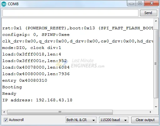
Now, open the Serial Monitor at a baud rate of 115200 and press the EN button on the ESP32. If all is well, you should observe the dynamic IP address assigned by your router. Take note of this address.
Step 3: Upload New Sketch Over-The-Air
Now, let’s proceed with uploading a new sketch over-the-air.
Keep in mind that it’s crucial to include the OTA code in every sketch you upload. Failure to do so will result in the loss of OTA capability, preventing future over-the-air uploads. Therefore, it’s advisable to modify the preceding code to incorporate your new code.
As an illustration, we’ll integrate a simple Blink sketch into the Basic OTA code. Ensure to adjust the SSID and password variables with your network credentials.
#include <WiFi.h>
#include <ESPmDNS.h>
#include <WiFiUdp.h>
#include <ArduinoOTA.h>

const char* ssid = "..........";
const char* password = "..........";

//variabls for blinking an LED with Millis
const int led = 2; // ESP32 Pin to which onboard LED is connected
unsigned long previousMillis = 0;  // will store last time LED was updated
const long interval = 1000;  // interval at which to blink (milliseconds)
int ledState = LOW;  // ledState used to set the LED
void setup() {

pinMode(led, OUTPUT);
  Serial.begin(115200);
  Serial.println("Booting");
  WiFi.mode(WIFI_STA);
  WiFi.begin(ssid, password);
  while (WiFi.waitForConnectResult() != WL_CONNECTED) {
    Serial.println("Connection Failed! Rebooting...");
    delay(5000);
    ESP.restart();
  }

  // Port defaults to 3232
  // ArduinoOTA.setPort(3232);

  // Hostname defaults to esp3232-[MAC]
  // ArduinoOTA.setHostname("myesp32");

  // No authentication by default
  // ArduinoOTA.setPassword("admin");

  // Password can be set with it's md5 value as well
  // MD5(admin) = 21232f297a57a5a743894a0e4a801fc3
  // ArduinoOTA.setPasswordHash("21232f297a57a5a743894a0e4a801fc3");

  ArduinoOTA
    .onStart([]() {
      String type;
      if (ArduinoOTA.getCommand() == U_FLASH)
        type = "sketch";
      else // U_SPIFFS
        type = "filesystem";

      // NOTE: if updating SPIFFS this would be the place to unmount SPIFFS using SPIFFS.end()
      Serial.println("Start updating " + type);
    })
    .onEnd([]() {
      Serial.println("\nEnd");
    })
    .onProgress([](unsigned int progress, unsigned int total) {
      Serial.printf("Progress: %u%%\r", (progress / (total / 100)));
    })
    .onError([](ota_error_t error) {
      Serial.printf("Error[%u]: ", error);
      if (error == OTA_AUTH_ERROR) Serial.println("Auth Failed");
      else if (error == OTA_BEGIN_ERROR) Serial.println("Begin Failed");
      else if (error == OTA_CONNECT_ERROR) Serial.println("Connect Failed");
      else if (error == OTA_RECEIVE_ERROR) Serial.println("Receive Failed");
      else if (error == OTA_END_ERROR) Serial.println("End Failed");
    });

  ArduinoOTA.begin();

  Serial.println("Ready");
  Serial.print("IP address: ");
  Serial.println(WiFi.localIP());
}

void loop() {
  ArduinoOTA.handle();
  //loop to blink without delay
  unsigned long currentMillis = millis();
  if (currentMillis - previousMillis >= interval) {
  // save the last time you blinked the LED
  previousMillis = currentMillis;
  // if the LED is off turn it on and vice-versa:
  ledState = not(ledState);
  // set the LED with the ledState of the variable:
  digitalWrite(led,  ledState);
  }
}
delay() function for LED blinking. This is because the delay() function halts the program. If an OTA request occurs while the ESP32 is paused waiting for the delay() to finish, the program will miss the request.After copying the above sketch to your Arduino IDE, navigate to the Tools > Port option. Look for something similar to: esp32-xxxxxx at your_esp_ip_address. If you cannot find it, consider restarting your IDE.
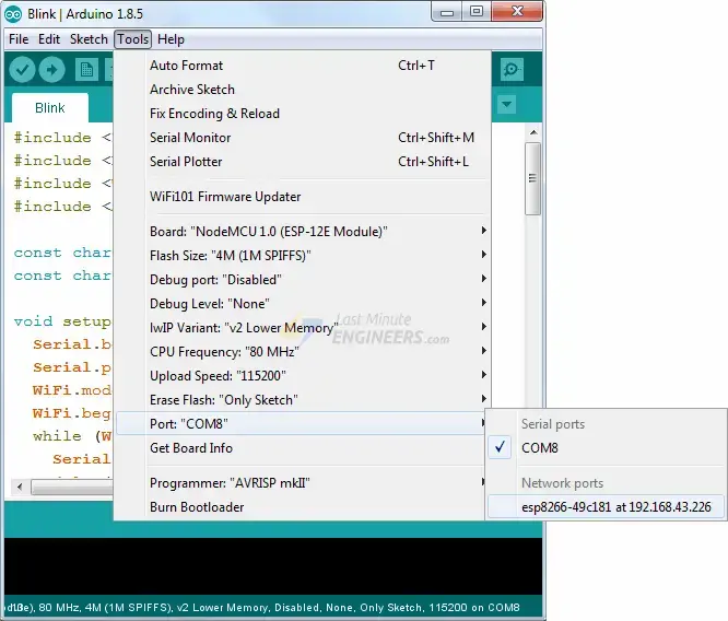
Select the port and click the Upload button. The new sketch will be uploaded within seconds, and the on-board LED should begin blinking.
Related article
- ESP32 Essentials: Exploring the Power of Bluetooth Classic
- ESP32 Fundamentals: Delving Into Hall Effect Sensor Technology
- Mastering Bluetooth Low Energy with ESP32 (BLE)
- Understanding ESP32 Sleep Modes for Optimal Power Usage
- Simplified ESP32 OTA Setup: Arduino IDE Web Updater Tutorial


