

A necessary component for projects involving clocks, timers, or counters is a 4-digit 7-segment display. However, directly connecting this display to an Arduino requires numerous pins, leaving limited space for additional sensors and modules.
Wouldn’t it be advantageous to control a 4-digit 7-segment display with fewer pins? Enter the TM1637 module, which only necessitates four connections in total: two for power and two for display control.
The 7-segment display, also known as the “seven segment display,” comprises seven LEDs arranged in an ‘8’-shaped pattern. Each LED, termed a segment, contributes to forming a digit when illuminated.
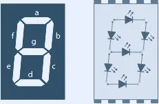
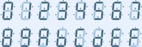
Each segment LED has one connection pin directly accessible from the rectangular plastic package, labeled ‘a’ through ‘g’. The remaining LED pins are interconnected to form a single common pin. Individual segments can be activated or deactivated by setting the corresponding pin to HIGH or LOW, akin to regular LEDs. By illuminating specific segments, various numerical characters and even rudimentary representations of letters can be created.
For further insights, refer to our comprehensive tutorial on 7-segment displays.
Parts Required
| Component Name | Buy Now |
| Arduino Uno REV3 | Amazon |
| DS3231 AT24C32 IIC RTC Module | Amazon |
| DHT11 Temperature Humidity Sensor Module | Amazon |
| TM1637 0.56″ LED Display | Amazon |
TM1637 Module Hardware Overview
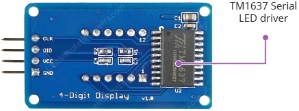
The TM1637 module integrates a traditional 0.36″ 4-digit 7-segment display with the TM1637 LED driver from Titan MicroElectronics, enabling control over all digits and the colon using just two I/O pins.
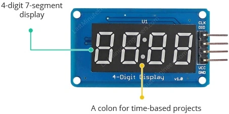
This module is well-suited for showcasing sensor data or temperature readings, and its inclusion of a colon makes it particularly useful for clock and time-oriented projects.
One of the key advantages of the TM1637 module is its ability to manage display refresh automatically once updated by the microcontroller, thus relieving the microcontroller for other essential tasks.
Additionally, the TM1637 offers various handy features, including brightness adjustment and independent segment control.
Operating within a 3.3 to 5 volt supply range, the TM1637 module communicates via a two-wire bus, necessitating only two data pins alongside VCC and ground. While employing its own proprietary data transfer protocol, Arduino libraries are readily available to simplify communication with the display.
Technical Specifications
Specifications include:
| Operating voltage | 3.3 – 5 VDC |
| Maximum Current Draw | 80mA |
| Reverse polarity protection | Yes |
| Display Size | 42 mm x 24 mm (1.65″ x .95″) |
| Display Height | 12 mm (0.47″) (typical) |
| Character Height | 9.14 mm (0.36″) |
For more information on the TM1637 driver, please refer to the datasheet below.
TM1637 Module Pinout
The TM1637 Module comprises only four pins, with the following pinout:
- CLK: This serves as the clock input pin.
- DIO: Designated as the Data I/O pin.
- VCC: Acts as the power supply pin, to be connected to a 3.3V to 5V power source.
- GND: Serves as the ground pin.
Wiring TM1637 Module with Arduino UNO
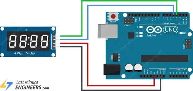
Connecting the TM1637 to an Arduino is straightforward, requiring only four wires: two for power and two for display control.
Begin by linking the VCC pin to the Arduino’s 5V output and the GND pin to ground. Then, connect the CLK and DIO pins to the Arduino’s digital pins 3 and 4, respectively.
Refer to the diagram below for the wiring configuration.
Since the module doesn’t rely on any pin-specific functionalities, it’s safe to use alternative pins. However, ensure to update the pin numbers in the code accordingly to accommodate any wiring alterations.
Library Installation
To effectively communicate with the TM1637 chip, you’ll require a library. The TM1637Display library, developed by Avishay Orpaz, is an outstanding choice. This library encompasses numerous built-in functions that streamline the process of controlling the display.
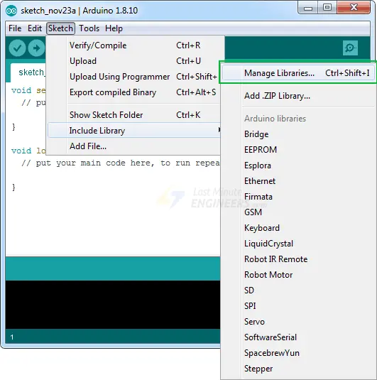
To install the library, follow these steps: Navigate to Sketch > Include Library > Manage Libraries… Wait for the Library Manager to download the libraries index and update the list of installed libraries.
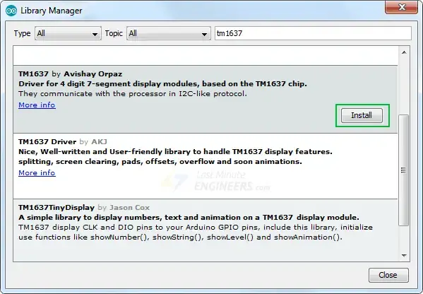
Filter your search by entering ‘tm1637’. Locate the TM1637 library by Avishay Orpaz. Click on that entry and then select Install.
Basic Arduino Code
Below is a simple test program that demonstrates various routines:
// Include the library
#include <TM1637Display.h>

// Define the connections pins
#define CLK 3
#define DIO 4

// Create a display object of type TM1637Display
TM1637Display display = TM1637Display(CLK, DIO);

// Create an array that turns all segments ON
const uint8_t allON[] = {0xff, 0xff, 0xff, 0xff};

// Create an array that turns all segments OFF
const uint8_t allOFF[] = {0x00, 0x00, 0x00, 0x00};

// Create an array that sets individual segments per digit to display the word "dOnE"
const uint8_t done[] = {
  SEG_B | SEG_C | SEG_D | SEG_E | SEG_G,           // d
  SEG_A | SEG_B | SEG_C | SEG_D | SEG_E | SEG_F,   // O
  SEG_C | SEG_E | SEG_G,                           // n
  SEG_A | SEG_D | SEG_E | SEG_F | SEG_G            // E
};

// Create degree celsius symbol
const uint8_t celsius[] = {
  SEG_A | SEG_B | SEG_F | SEG_G,  // Degree symbol
  SEG_A | SEG_D | SEG_E | SEG_F   // C
};

void setup() {

}

void loop() {
	// Set the brightness to 5 (0=dimmest 7=brightest)
	display.setBrightness(5);

	// Set all segments ON
	display.setSegments(allON);

	delay(2000);
	display.clear();

	// Show counter 0-9
	int i;
	for (i = 0; i < 10; i++) {
		display.showNumberDec(i);
		delay(50);
	}

	delay(2000);
	display.clear();

	display.showNumberDec(-12);			// Prints _-12
	delay(2000);
	display.clear();

	display.showNumberDec(-999);		// Prints -999
	delay(2000);
	display.clear();

	display.showNumberDec(31, false);	// Prints __31
	delay(2000);
	display.clear();

	display.showNumberDec(31, true);	// Prints 0031
	delay(2000);
	display.clear();

	display.showNumberDec(14, false, 2, 1);	// Prints _14_
	delay(2000);
	display.clear();

	display.showNumberDec(-5, false, 3, 0);	// Prints _-5_
	delay(2000);
	display.clear();

	// Prints 12:34
	display.showNumberDecEx(1234, 0b11100000, false, 4, 0);

	delay(2000);
	display.clear();

	// Prints 15°C
	int temperature = 15;
	display.showNumberDec(temperature, false, 2, 0);
	display.setSegments(celsius, 2, 2);

	delay(2000);
	display.clear();

	// Prints dOnE
	display.setSegments(done);

	while(1);
}
Code Explanation:
The sketch begins by including the TM1637Display library and defining the connection pins for the TM1637 display.
#include <TM1637Display.h>

#define CLK 3
#define DIO 4
The next step involves creating an object of the TM1637Display class. The TM1637Display constructor requires two inputs: the CLK pin and the DIO pin.
TM1637Display display = TM1637Display(CLK, DIO);
Each segment of each digit in the TM1637 display can be controlled individually by setting the corresponding pin to HIGH or LOW, similar to a regular LED. This enables the creation of various numerical characters and basic representations of letters by illuminating specific segments.
To demonstrate this, four arrays are defined before the setup section of the code. The first array turns all segments ON, the second turns all segments OFF, the third displays the word ‘dOnE’, and the fourth displays the ‘°C’ symbol. These arrays are passed to the setSegments() function to display them.
There are two methods for defining these arrays. The first method uses hexadecimal numbers. For instance, 0xFF translates to binary 11111111, turning all segments ON, while 0x00 turns all segments OFF. Similarly, 0xEF (11101111 in binary) turns all segments on except segment E.
// Create an array that turns all segments ON
const uint8_t allON[] = {0xff, 0xff, 0xff, 0xff};

// Create an array that turns all segments OFF
const uint8_t allOFF[] = {0x00, 0x00, 0x00, 0x00};
Another method involves specifying which segments to turn on, which is simpler. The first array displays ‘dOnE’, while the second displays ‘°C’.
// Create an array that sets individual segments per digit to display the word "dOnE"
const uint8_t done[] = {
  SEG_B | SEG_C | SEG_D | SEG_E | SEG_G,           // d
  SEG_A | SEG_B | SEG_C | SEG_D | SEG_E | SEG_F,   // O
  SEG_C | SEG_E | SEG_G,                           // n
  SEG_A | SEG_D | SEG_E | SEG_F | SEG_G            // E
};

// Create °C symbol
const uint8_t celsius[] = {
  SEG_A | SEG_B | SEG_F | SEG_G,	// °
  SEG_A | SEG_D | SEG_E | SEG_F		// C
};
The setup section is left blank since there’s nothing to configure.
void setup() {
}
In the loop section, various library functions are utilized, each serving different purposes.
setBrightness(brightness,on)
This function adjusts the display’s brightness. You can select a brightness level from 0 (lowest brightness) to 7 (highest brightness).
The second argument is optional and controls the display’s state. You can pass true (display ON) or false (display OFF). For instance, display.setBrightness(5) sets the brightness to 5, while display.setBrightness(5, false) turns off the display.
setSegments(segments[],length,position)
This function sets individual segments of a display. The first argument specifies the array containing segment information. The second argument specifies how many digits should be updated (0–4). For instance, to print “dOnE”, use 4, and for “°C”, use 2. The third argument specifies the position from which you want to print (0-leftmost, 3-rightmost).
The second and third arguments are optional. If you want to update all display digits, you can skip them. For example, the following code first turns on all segments of the display and then prints “dOnE”.
// Set all segments ON
display.setSegments(allON);

// Prints dOnE
display.setSegments(done);
If you only want to update the last two digits of the display to print the “°C” symbol, use:
// Prints __°C
display.setSegments(celsius, 2, 2);
showNumberDec(number,leading_zeros,length,position)
This is the most commonly used function. The first argument specifies the number to be displayed. For example, the following code counts from 0 to 9 and then displays -12 and -999.
// Show counter 0-9
int i;
for (i = 0; i < 10; i++) {
	display.showNumberDec(i);
	delay(50);
}

display.showNumberDec(-12);			// Prints _-12

display.showNumberDec(-999);		// Prints -999
The second argument can add leading zeros to a number. Setting this to true adds leading zeros, while false prints the number as-is.
display.showNumberDec(31, false);        // Prints __31

display.showNumberDec(31, true);        // Prints 0031
The third and fourth arguments specify the number of digits to be updated (0-4) and where to print from (0-leftmost, 3-rightmost), respectively.
To center the number on the display, use:
display.showNumberDec(14, false, 2, 1);        // Prints _14_

display.showNumberDec(-5, false, 3, 0);        // Prints _-5_
showNumberDecEx(number,dots,leading_zeros,length,position)
This function extends showNumberDec(). Only the second argument differs, allowing you to control the display’s dots. Use the following values for TM1637 displays with dots between each digit:
| Argument | Example |
| 0b10000000 | 1.234 |
| 0b01000000 | 12.34 |
| 0b00100000 | 123.4 |
| 0b11100000 | 1.2.3.4 |
For TM1637 displays with just a colon:
| Argument | Example |
| 0b01000000 | 12:34 |
For TM1637 displays with dots and a colon:
| Argument | Example |
| 0b11100000 | 1.2:3.4 |
So, if you want to show a clock with the center colon enabled, you’d write:
// Prints 12:34
display.showNumberDecEx(1234, 0b11100000, false, 4, 0);
Arduino Project 1 – Creating a Thermometer with TM1637 and DHT11/DHT22
The TM1637 display is an ideal choice for presenting sensor data like temperature, humidity, voltage, or speed. This project focuses on showcasing temperature readings from a DHT11 sensor on the TM1637 display.
If you’re new to the DHT11 module, it’s recommended to review a tutorial for better understanding.
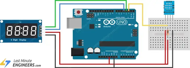
Wiring
Refer to the wiring diagram below for connecting the DHT11 sensor and the TM1637 display to Arduino.
Arduino Code
The provided sketch interacts with the DHT11 sensor to display temperature readings on the TM1637 display. Temperature values are presented in both Celsius and Fahrenheit every 2 seconds.
Please ensure to install the Adafruit DHT sensor and the Adafruit Unified Sensor libraries as well.
// Include the libraries
#include <TM1637Display.h>
#include <Adafruit_Sensor.h>
#include <DHT.h>

// Define the connections pins
#define CLK 3
#define DIO 4
#define DHTPIN 5

// Create variable
int temperature_celsius;
int temperature_fahrenheit;

// Create °C symbol
const uint8_t celsius[] = {
	SEG_A | SEG_B | SEG_F | SEG_G,  // Circle
	SEG_A | SEG_D | SEG_E | SEG_F   // C
};

// Create °F symbol
const uint8_t fahrenheit[] = {
	SEG_A | SEG_B | SEG_F | SEG_G,  // Circle
	SEG_A | SEG_E | SEG_F | SEG_G   // F
};

// Uncomment whatever type you're using!
//#define DHTTYPE DHT11   // DHT 11
#define DHTTYPE DHT22   // DHT 22  (AM2302)

// Create display object of type TM1637Display
TM1637Display display = TM1637Display(CLK, DIO);

// Create dht object of type DHT:
DHT dht = DHT(DHTPIN, DHTTYPE);

void setup() {
	// Set the display brightness (0-7)
	display.setBrightness(5);

	// Clear the display
	display.clear();

	// Setup sensor
	dht.begin();
}

void loop() {
	// Read the temperature as Celsius and Fahrenheit
	temperature_celsius = dht.readTemperature();
	temperature_fahrenheit = dht.readTemperature(true);

	// Display the temperature in celsius format
	display.showNumberDec(temperature_celsius, false, 2, 0);
	display.setSegments(celsius, 2, 2);
	delay(1000);

	// Display the temperature in fahrenheit format
	display.showNumberDec(temperature_fahrenheit, false, 2, 0);
	display.setSegments(fahrenheit, 2, 2);
	delay(1000);
}
Arduino Project 2 – Creating a clock with TM1637 and DS3231
The TM1637 display is commonly paired with the DS3231 RTC module to create a 24-hour clock.
If you’re not familiar with the DS3231 RTC module, it’s recommended to review a tutorial for better understanding.
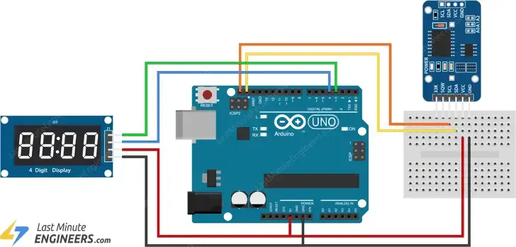
Wiring
Refer to the wiring diagram below to connect the DS3231 and the TM1637 display to Arduino.
Arduino Code
The following sketch displays the time in a 24-hour format. This code utilizes the Adafruit RTC library, so please install it as well.
// Include the libraries
#include "RTClib.h"
#include <TM1637Display.h>

// Define the connections pins
#define CLK 3
#define DIO 4

// Create rtc and display object
RTC_DS3231 rtc;
TM1637Display display = TM1637Display(CLK, DIO);

void setup() {
	// Begin serial communication
	Serial.begin(9600);

	// Check if RTC is connected correctly
	if (! rtc.begin()) {
		Serial.println("Couldn't find RTC");
		while (1);
	}
	// Check if the RTC lost power and if so, set the time
	if (rtc.lostPower()) {
		Serial.println("RTC lost power, lets set the time!");
		// The following line sets the RTC to the date & time this sketch was compiled:
		rtc.adjust(DateTime(F(__DATE__), F(__TIME__)));
		// This line sets the RTC with an explicit date & time, for example to set
		// January 21, 2014 at 3am you would call:
		//rtc.adjust(DateTime(2014, 1, 21, 3, 0, 0));
	}

	// Set the display brightness (0-7)
	display.setBrightness(5);

	// Clear the display
	display.clear();
}

void loop() {
	// Get current date and time
	DateTime now = rtc.now();

	// Create time format to display
	int displaytime = (now.hour() * 100) + now.minute();

	// Display the current time in 24 hour format with leading zeros and a center colon enabled
	display.showNumberDecEx(displaytime, 0b11100000, true);

	delay(1000);
}
Related article
- Step-by-Step Guide: Arduino Integration with I2C LCD Screen
- Arduino MAX7219 LED Matrix Display: Complete Setup Guide
- Step-by-Step: Integrating Seven Segment Display with Arduino
- Arduino LCD Tutorial: How to Interface a 16×2 Character LCD Module
- Arduino RFID Tutorial: Interface RC522 RFID Module and How It Works


