
Dot matrix displays are ubiquitous among Arduino enthusiasts. They’re widely used in modern outdoor LED displays for showcasing characters, symbols, and images.
For controlling these displays, the MAX7219 stands out as an excellent choice. It efficiently manages a single dot matrix and can be daisy-chained for larger setups with two or more matrices.
In conclusion, these displays offer both enjoyment and practicality. Let’s dive in and explore!
Parts Required
| Component Name | Buy Now |
| Arduino Uno REV3 | Amazon |
| MAX7219 Dot Matrix Module | Amazon |
| MAX7219 8×8 Dot Matrix LED Display Module 5V | Amazon |
MAX7219 Module Overview
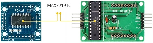
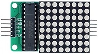
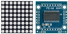
Various MAX7219 breakout boards are accessible, with two standout options: the generic module and the FC-16 module.
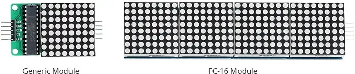
A typical MAX7219 module incorporates an 8×8 dot matrix display alongside a MAX7219 LED display driver. Let’s delve into their functionalities.
The Dot Matrix Display
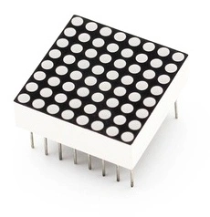
An 8×8 dot matrix display typically comprises 16 pins, 8 for rows and 8 for columns. To minimize pin count, all rows and columns interconnect. Otherwise, it would necessitate 65 pins for an 8×8 display, one for each LED and one for a common anode or cathode connector. Merging rows and columns reduces the requirement to 16 pins, a method known as Multiplexing.
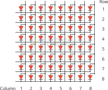
In this approach, each column activates briefly while addressing the corresponding row to illuminate LEDs. Consequently, only a maximum of eight LEDs illuminate simultaneously. The columns toggle rapidly (hundreds to thousands of times per second), creating the illusion of a fully lit display to the human eye.
MAX7219 Chip
However, multiplexing mandates constant display refreshing to maintain image stability.
Enter the MAX7219 Chip, which manages control and refresh tasks autonomously. By transmitting serial commands via the 4-pin SPI interface, it handles operations effortlessly.
It can govern 64 individual LEDs while preserving their brightness. After the microcontroller updates the display, the MAX7219 refreshes it at 800 Hz, liberating the microcontroller for other tasks.
Moreover, the MAX7219 features a power-saving mode for display deactivation, conserving power. It also suppresses LED activity during startup, averting erratic displays initially.
The MAX7219 utilizes the SPI interface, requiring only 3 data pins for microcontroller linkage. Multiple modules can be daisy-chained using the same 3 wires, facilitating expanded displays.
Configuring Maximum Current and Brightness
The MAX7219 provides options for adjusting display brightness via hardware, software, or both.
Hardware Adjustment
On the MAX7219 breakout board, a resistor (RSet) is present for modifying brightness at the hardware level.
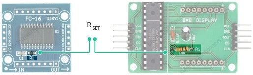
This resistor regulates the maximum current delivered to the LEDs, thereby influencing the overall brightness.
Refer to the table below to determine the appropriate resistor values based on your LED matrix’s voltage and forward current. For instance, a 2V 20 mA LED necessitates a 28kΩ resistor.
| ISEG (mA) | VLED (V) | ||||
| 1.5 | 2.0 | 2.5 | 3.0 | 3.5 | |
| 40 | 12.2 | 11.8 | 11.0 | 10.6 | 9.69 |
| 30 | 17.8 | 17.1 | 15.8 | 15.0 | 14.0 |
| 20 | 29.8 | 28.0 | 25.9 | 24.5 | 22.6 |
| 10 | 66.7 | 63.7 | 59.3 | 55.4 | 51.2 |
Software Adjustment
Software-based brightness adjustment will be covered later in this tutorial.
MAX7219 Module Pinout
Regardless of the variant chosen, the module features two connectors.
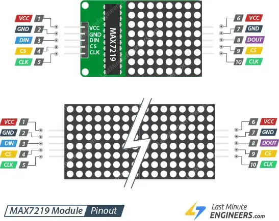
Input Connector
Breakout pins on one end facilitate communication with the microcontroller.
VCC: Connects to 5V. Due to high current draw (up to 1A at maximum brightness), an external power supply is preferable over Arduino’s 5V. To prevent overheating the voltage regulator, maintain brightness below 25% with Arduino’s 5V supply.
GND: Serves as the common ground.
DIN: Data pin. Link to any digital pin on the microcontroller.
CS/LOAD: Chip Select (or LOAD). Attach to any digital pin on the microcontroller.
CLK: Clock pin. Connect to any digital pin on the microcontroller.
Output Connector
Breakout pins on the opposite end enable daisy-chaining displays.
VCC: Links to 5V on the subsequent module.
GND: Links to GND on the subsequent module.
DOUT: Data Out. Connects to the DIN pin of the subsequent module.
CS/LOAD: Connects to CS / LOAD on the subsequent module.
CLK: Connects to CLK on the subsequent module.
Wiring MAX7219 Module with Arduino UNO
Now that we’re well-versed with the module, let’s commence linking it to our Arduino!
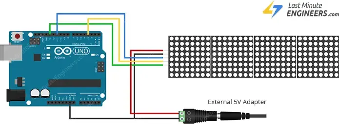
To begin, establish the module’s power supply connections. Given the display’s substantial current consumption, opt for an external power supply over the Arduino board’s 5V. If employing a single MAX7219 module, powering it directly from the Arduino is feasible but not recommended.
Next, let’s interconnect the SPI pins. Note that each Arduino board features a distinct set of SPI pins, necessitating appropriate connections. For Arduino boards like UNO/Nano V3.0, these pins comprise digital 13 (SCK), 12 (MISO), 11 (MOSI), and 10 (SS).
If utilizing a different Arduino board, refer to the official documentation for SPI pin locations prior to proceeding.
Below are the wiring configurations for the Generic MAX7219 Module and the FC-16 MAX7219 Module.
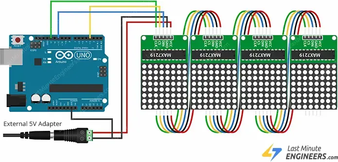
For daisy-chaining multiple displays to form a larger display, link the DOUT of the first display to the DIN of the subsequent display. VCC, GND, CLK, and CS will be shared across displays.
Once the module is interconnected with the Arduino, it’s time to delve into coding!
Library Installation
Managing the MAX7219 module can be intricate. Thankfully, the MD Parola library simplifies this task by concealing the complexities, enabling easy control of the display through straightforward commands.
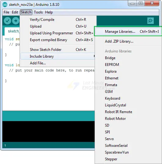
To incorporate the library, follow these steps:
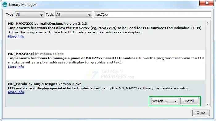
Go to Sketch > Include Library > Manage Libraries…
Allow the Library Manager to download the library index and update the list of installed libraries.
Filter your search by entering ‘max72xx’.
Locate MD_MAX72XX by MajicDesigns.
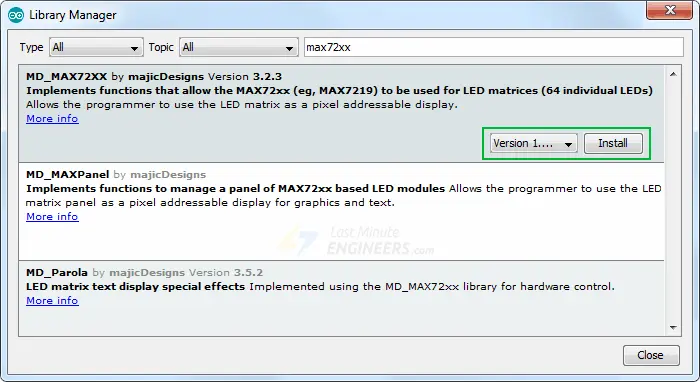
Click on the entry and choose Install.
Additionally, install the MD_Parola Library, which complements the MD_MAX72XX library, facilitating various text animations such as scrolling and sprite text effects.
Arduino Example Code 1 – Text Display
Our initial experiment entails presenting straightforward text without any animation.
Before uploading the sketch, adjust the following two variables:
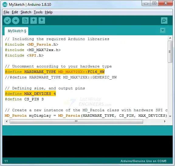
- Set the
HARDWARE_TYPEvariable toGENERIC_HWif utilizing a module with a green PCB and a through-hole MAX7219 IC.
- Alternatively, set it to
FC16_HWif employing a module with a blue PCB and an SMD MAX7219 IC.
Specify the number of MAX7219 ICs being utilized with the MAX_DEVICES variable. Each MAX7219 IC counts as one device. For instance, if controlling an 8×32 display, set MAX_DEVICES to 4 as it involves four MAX7219 ICs.
After configuring, test out the sketch, and we’ll delve into its details.
// Including the required Arduino libraries
#include <MD_Parola.h>
#include <MD_MAX72xx.h>
#include <SPI.h>

// Uncomment according to your hardware type
#define HARDWARE_TYPE MD_MAX72XX::FC16_HW
//#define HARDWARE_TYPE MD_MAX72XX::GENERIC_HW

// Defining size, and output pins
#define MAX_DEVICES 4
#define CS_PIN 3

// Create a new instance of the MD_Parola class with hardware SPI connection
MD_Parola myDisplay = MD_Parola(HARDWARE_TYPE, CS_PIN, MAX_DEVICES);

void setup() {
	// Intialize the object
	myDisplay.begin();

	// Set the intensity (brightness) of the display (0-15)
	myDisplay.setIntensity(0);

	// Clear the display
	myDisplay.displayClear();
}

void loop() {
	myDisplay.setTextAlignment(PA_LEFT);
	myDisplay.print("Left");
	delay(2000);

	myDisplay.setTextAlignment(PA_CENTER);
	myDisplay.print("Center");
	delay(2000);

	myDisplay.setTextAlignment(PA_RIGHT);
	myDisplay.print("Right");
	delay(2000);

	myDisplay.setTextAlignment(PA_CENTER);
	myDisplay.setInvert(true);
	myDisplay.print("Invert");
	delay(2000);

	myDisplay.setInvert(false);
	myDisplay.print(1234);
	delay(2000);
}
Output
To view the output correctly, ensure the display is properly oriented. For generic modules, confirm the MAX7219 IC is positioned on top. For FC-16 modules, ensure the DIN side is on the right.
If all is well, you should observe the specified output.

Code Explanation
First, we include the necessary Arduino libraries: MD_Parola, MD_MAX72xx, and SPI. MD_MAX72XX handles hardware-specific LED matrix functions, while MD_Parola manages text effects. SPI facilitates communication with the display.
#include <MD_Parola.h>
#include <MD_MAX72xx.h>
#include <SPI.h>
Next, we define the hardware being used. Since we’re using an FC-16 module with 4 MAX7219 ICs, we set HARDWARE_TYPE to FC16_HW and MAX_DEVICES to 4. CS_PIN specifies the display’s CS pin.
#define HARDWARE_TYPE MD_MAX72XX::FC16_HW
#define MAX_DEVICES 4
#define CS_PIN 3
We create an instance of the MD_Parola class using MD_Parola() function. Parameters include hardware type, CS pin, and number of MAX7219 ICs.
MD_Parola myDisplay = MD_Parola(HARDWARE_TYPE, CS_PIN, MAX_DEVICES);
In setup(), we initialize the object, set display intensity, and clear the display.
void setup() {
  myDisplay.begin();
  myDisplay.setIntensity(0);
  myDisplay.displayClear();
}
In loop(), we set text alignment using setTextAlignment(). We print text (“Left”, “Center”, “Right”) using print() and delay for 2 seconds between each print. setInvert() inverts the display when set to true.
void loop() {
	myDisplay.setTextAlignment(PA_LEFT);
	myDisplay.print("Left");
	delay(2000);

	myDisplay.setTextAlignment(PA_CENTER);
	myDisplay.print("Center");
	delay(2000);

	myDisplay.setTextAlignment(PA_RIGHT);
	myDisplay.print("Right");
	delay(2000);

	myDisplay.setTextAlignment(PA_CENTER);
	myDisplay.setInvert(true);
	myDisplay.print("Invert");
	delay(2000);

	myDisplay.setInvert(false);
	myDisplay.print(1234);
	delay(2000);
}
Arduino Example Code 2 – Scrolling Text
When your message exceeds the size of a dot matrix display, scrolling text becomes essential. This example illustrates how to implement this effect.
// Including the required Arduino libraries
#include <MD_Parola.h>
#include <MD_MAX72xx.h>
#include <SPI.h>

// Uncomment according to your hardware type
#define HARDWARE_TYPE MD_MAX72XX::FC16_HW
//#define HARDWARE_TYPE MD_MAX72XX::GENERIC_HW

// Defining size, and output pins
#define MAX_DEVICES 4
#define CS_PIN 3

// Create a new instance of the MD_Parola class with hardware SPI connection
MD_Parola myDisplay = MD_Parola(HARDWARE_TYPE, CS_PIN, MAX_DEVICES);

void setup() {
	// Intialize the object
	myDisplay.begin();

	// Set the intensity (brightness) of the display (0-15)
	myDisplay.setIntensity(0);

	// Clear the display
	myDisplay.displayClear();

	myDisplay.displayScroll("Hello", PA_CENTER, PA_SCROLL_LEFT, 100);
}

void loop() {
	if (myDisplay.displayAnimate()) {
		myDisplay.displayReset();
	}
}
If everything goes well, you will see the following output.
Code Explanation
The setup section remains consistent with the previous example, with the addition of the displayScroll() function call.
myDisplay.displayScroll("Hello", PA_CENTER, PA_SCROLL_LEFT, 100);
The displayScroll() function accepts four arguments:
pText– the text string to be scrolled.
align– sets the alignment of the text during optional pauses (e.g., PA_CENTER, PA_LEFT, PA_RIGHT).
textEffect– specifies the scrolling effect (e.g., PA_SCROLL_LEFT).
speed– determines the speed of the animation in milliseconds per frame.
In the loop section, we use displayAnimate() to execute the scrolling animation. If the scrolling is complete, displayReset() resets the display for continuous scrolling.
void loop() {
	if (myDisplay.displayAnimate()) {
		myDisplay.displayReset();
	}
}
Related article
- Step-by-Step Guide: Arduino Integration with I2C LCD Screen
- Step-by-Step: Integrating Seven Segment Display with Arduino
- Arduino LCD Tutorial: How to Interface a 16×2 Character LCD Module
- Arduino RFID Tutorial: Interface RC522 RFID Module and How It Works
- Arduino HC-05 Bluetooth Module Tutorial: Step-by-Step Guide


