

This article, part of our ESP32 Basics series, illustrates the process of reading analog values with the ESP32 using the Arduino IDE.
The ability to read analog values is particularly valuable when working with a diverse range of sensors and variable components. Examples include trimpots, joysticks, sliders, and force-sensitive resistors, among others.
ESP32 ADC Pins
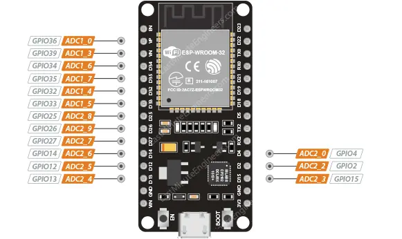
The ESP32 is equipped with two 12-bit SAR (Successive Approximation Register) ADCs: ADC1 and ADC2. These ADCs support measurements on a total of 18 channels, referred to as analog-enabled pins. ADC1 can be accessed via eight GPIOs, specifically GPIOs 32 to 39, while ADC2 is available on ten GPIOs: GPIOs 0, 2, 4, and 12 to 15, as well as GPIOs 25 to 27.
However, it’s important to note that the DEVKIT V1 DOIT board, which has 30 GPIOs, only provides 15 ADC channels, as depicted in the figure below.
The ADC integrated into the ESP32 features a 12-bit resolution, allowing it to detect 4096 discrete analog levels. In simpler terms, it converts input voltages ranging from 0 to 3.3V (the operating voltage) into integer values ranging from 0 to 4095. Consequently, this results in a resolution of 3.3 volts divided by 4096 units, which equals 0.0008 volts (0.8 mV) per unit.
Additionally, the ADC resolution and channel range can be adjusted programmatically to meet specific requirements.
Limitations of the ESP32’s ADC
While the ESP32 offers many capabilities, it’s important to be aware of certain limitations when it comes to its ADC functionality. Here are some key points to consider:
Unusable when WiFi is Enabled
When Wi-Fi is enabled on the ESP32, the ADC2 pins become unavailable for use. Given the high likelihood of Wi-Fi usage in microcontroller applications, it restricts the ADC functionality to ADC1 only.
ADC Input Range
The ADC on the ESP32 can measure voltages within the range of 0 to 3.3V. It is not capable of directly measuring analog voltages between 0V and 5V. This limitation should be taken into account when designing your circuits.
ADC Accuracy
While one might expect linear behavior from the ADC, the ADC converters on the ESP32 are inherently non-linear. This means that the measured values may not follow a straight line as expected. Detailed information and discussions about this non-linearity can be found on platforms like GitHub.
The graph below illustrates the non-linearities at the lower and upper ends of the input voltage range.
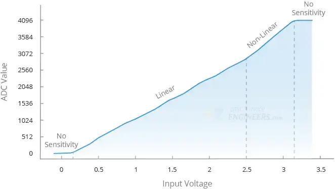
As a result, the ESP32 cannot distinguish between voltages very close to each other. For instance, it cannot differentiate between 3.2V and 3.3V; the measured value will be the same (4095). Similarly, it cannot distinguish between 0V and 0.13V signals; the measured value will be the same (0).
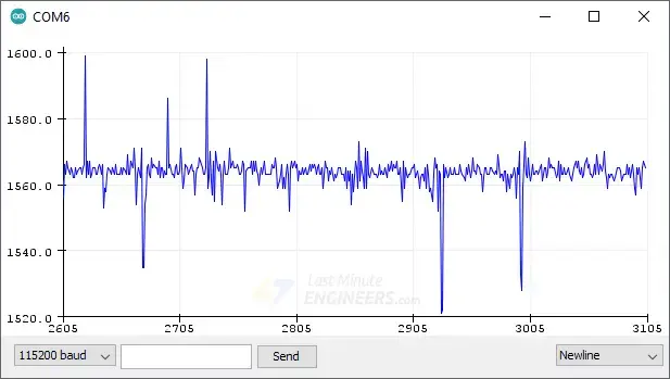
Electrical Noise
The ADC of the ESP32 is susceptible to electrical noise, which can introduce slight fluctuations in measurements. To mitigate this, techniques such as adding a capacitor at the output and oversampling can be employed to improve accuracy and reduce noise.
It’s essential to consider these limitations when working with the ESP32’s ADC to ensure accurate and reliable measurements.
The analogRead() Function
Obtaining analog values from a GPIO pin is a simple process. In the Arduino IDE, you can utilize the analogRead() function, which takes the GPIO pin number you wish to read as an argument.
To read an analog value from a GPIO pin, use the following syntax:
analogRead(GPIO);
Reading a potentiometer
To demonstrate how to utilize the ADC on the ESP32, we will present a simple example that involves reading an analog value from a potentiometer.
Hardware Setup
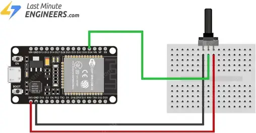
Let’s set up a basic circuit using a potentiometer for this example.
Begin by inserting the potentiometer into your breadboard. Connect the middle pin of the potentiometer to GPIO 34 on your ESP32. Then, connect one of the outer pins of the potentiometer (it doesn’t matter which one) to the 3V3 pin of the ESP32, and connect the other outer pin to the ground.
Parts Required
| Component Name | Buy Now |
| ESP32-WROOM-32 Development | Amazon |
| Taiss 40PCS Potentiometer Kit with Rotary knobs | Amazon |
| Breadboard | Amazon |
Example Code
Upload the following code to your ESP32. This code reads the potentiometer’s value and prints the results to the Serial Monitor.
// Potentiometer is connected to GPIO 34 (Analog ADC1_CH6)
const int potPin = 34;

// variable for storing the potentiometer value
int potValue = 0;

void setup() {
  Serial.begin(115200);
  delay(1000);
}

void loop() {
  // Reading potentiometer value
  potValue = analogRead(potPin);
  Serial.print("Analog value: ");
  Serial.println(potValue);
  delay(500);
}
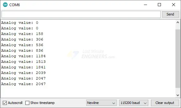
Once you have uploaded the sketch, open the Serial Monitor with a baud rate of 115200 and press the EN button on the ESP32.
You should observe a value between 0 and 4095, depending on the current position of the potentiometer’s knob, being displayed in the Serial Monitor. Try rotating the knob on the potentiometer to observe how the values change.
Code Explanation:
The code starts by defining the GPIO pin to which the potentiometer is connected, specified as GPIO 34.
const int potPin = 34;
Additionally, a variable is declared to store the potentiometer values.
int potValue = 0;
In the setup() function, the serial communication with the PC is initialized.
Serial.begin(115200);
Inside the loop(), the analogRead() function is used to measure the voltage on the potPin. The obtained value is then stored in the potValue variable.
potValue = analogRead(potPin);
Finally, the values obtained from the potentiometer are printed to the Serial Monitor.
Serial.print("Analog value: ");
Serial.println(potValue);
potPin as an input since this is automatically handled each time analogRead() is called.Other ADC Functions
In addition to the basic analogRead() function, there are several other useful ADC functions available for further control and customization:
analogReadMilliVolts(pin):Retrieves the ADC value for a specific pin or ADC channel in millivolts.
analogReadResolution(bits):Sets the resolution for sampling and reading ADC values. The default is 12-bit resolution, but it can be adjusted within the range of 9 to 12 bits.
analogSetWidth(bits):Configures the hardware sample and read resolution. The default is 12-bit resolution, but it can be set from 9 to 12 bits. Each bit increase doubles the number of available values.
analogSetCycles(cycles):Determines the number of cycles per sample. The default is 8 cycles, but it can be adjusted from 1 to 255. Increasing the number of cycles can improve ADC accuracy.
analogSetSamples(samples):Specifies the number of samples taken within the ADC range. The default is 1 sample, but increasing the number of samples can enhance sensitivity and averaging.
analogSetClockDiv(clockDiv):Sets the ADC clock divider. The default is 1, but it can be adjusted from 1 to 255. A higher clock division ratio can be used for slower ADC conversions.
analogSetAttenuation(attenuation):Sets the input attenuation for all ADC pins. The default is ADC_11db. Other accepted values include ADC_0db, ADC_2_5db, and ADC_6db. The attenuation affects the measurable input voltage range.
analogSetPinAttenuation(pin, attenuation):Similar to the previous function, but sets the input attenuation for a specific pin.
adcAttachPin(pin):Associates a pin with the ADC, clearing any other analog mode. It returns true if the configuration is successful; otherwise, false.
adcStart(pin):Initiates an ADC conversion on the attached pin’s bus.
adcBusy(pin):Checks if a conversion is currently running on the pin’s ADC bus and returns true or false.
adcEnd(pin):Waits for the ADC conversion to finish and retrieves the result as a 16-bit integer.
These additional ADC functions provide greater control over the ADC’s resolution, sampling, clock, attenuation, and pin association, enabling fine-tuning and customization to suit specific project requirements.
Related article
- ESP32 Pinout Reference: Simplify Hardware Connections with Ease
- ESP32 Capacitive Touch Pins: Basics for Interactive Projects
- Step-by-Step Tutorial: Setting Up ESP32 Board in Arduino IDE


