
The ESP32 offers a significant advantage over the ESP8266 with its abundance of GPIOs. This means you won’t need to manage or multiplex your IO pins. Nonetheless, it’s essential to bear in mind a few considerations, so please carefully review the pinout information.
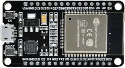
Please be aware that the pinout reference provided pertains specifically to the widely used 30-pin ESP32 devkit v1 development board. While not all ESP32 development boards expose every pin, each pin functions identically regardless of the specific development board you utilize.
Parts Required
| Component Name | Buy Now |
| ESP32-WROOM-32 Development | Amazon |
ESP32 Peripheral and Input/Output (I/O)
While the ESP32 boasts a total of 48 GPIO pins, only 25 of them are accessible via the pin headers on both sides of the development board. These pins are versatile and can be assigned various peripheral functions, such as:
| 15 ADC channels | 15 channels of 12-bit SAR ADC with selectable ranges of 0-1V, 0-1.4V, 0-2V, or 0-4V |
| 2 UART interfaces | 2 UART interfaces with flow control and IrDA support |
| 25 PWM outputs | 25 PWM pins to control things like motor speed or LED brightness |
| 2 DAC channels | Two 8-bit DACs to generate true analog voltages |
| SPI, I2C and I2S interface | Three SPI and one I2C interfaces for connecting various sensors and peripherals, as well as two I2S interfaces for adding sound to your project |
| 9 Touch Pads | 9 GPIOs with capacitive touch sensing |
The ESP32’s pin multiplexing feature enables multiple peripherals to share a single GPIO pin. This means that a single GPIO pin can serve as an ADC input, DAC output, or touch pad, among other possibilities.
For comprehensive details about the ESP32, please consult the datasheet.
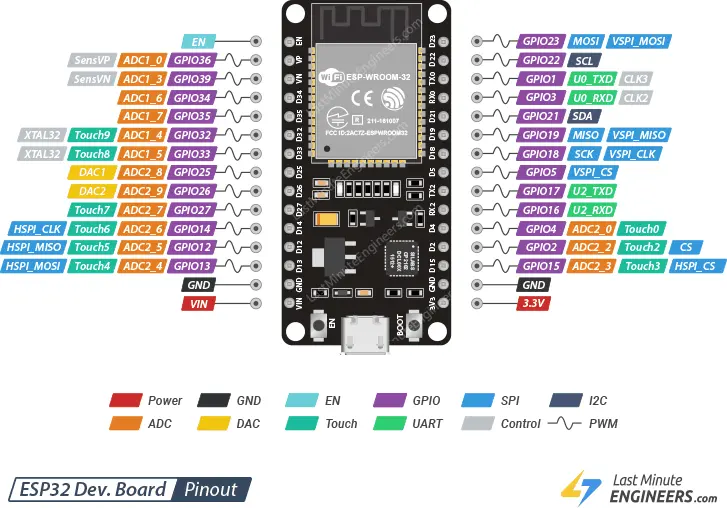
ESP32 Pinout
The ESP32 DevKit V1 development board comprises a total of 30 pins. To simplify usage, pins with similar functions are grouped together. Here is the pinout breakdown:
Now, let’s examine each ESP32 pin individually, along with its respective function.
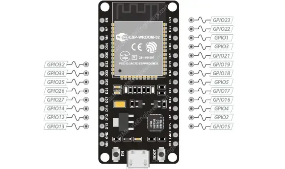
GPIO Pins
The ESP32 development board offers 25 GPIO pins that can be assigned different functionalities by programming the appropriate registers. These GPIOs come in various types, including digital-only, analog-enabled, and capacitive-touch-enabled. Analog-enabled GPIOs and capacitive-touch-enabled GPIOs can be configured as digital GPIOs. Additionally, most of the digital GPIOs can have internal pull-up or pull-down resistors configured or set to high impedance.

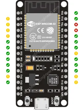
Determining Safe-to-Use GPIOs on the ESP32?
While the ESP32 provides numerous pins with diverse functions, it’s crucial to identify which pins are suitable for your projects. The table below outlines the pins that are considered safe to use, those that require careful attention due to unpredictable behavior (particularly during boot), and the pins that are recommended to be avoided.
 – Safe-to-Use Pins: These pins are your top priority and can be utilized without concern.
 – Use with Caution Pins: Exercise caution when using these pins, as their behavior, especially during boot, can be unpredictable. Only use them when absolutely necessary.
 – Avoid Using Pins: It is recommended to avoid using these pins altogether.
| Label | GPIO | Safe to use? | Reason |
| D0 | 0 | | must be HIGH during boot and LOW for programming |
| TX0 | 1 | | Tx pin, used for flashing and debugging |
| D2 | 2 | | must be LOW during boot and also connected to the on-board LED |
| RX0 | 3 | | Rx pin, used for flashing and debugging |
| D4 | 4 | | |
| D5 | 5 | | must be HIGH during boot |
| D6 | 6 | | Connected to Flash memory |
| D7 | 7 | | Connected to Flash memory |
| D8 | 8 | | Connected to Flash memory |
| D9 | 9 | | Connected to Flash memory |
| D10 | 10 | | Connected to Flash memory |
| D11 | 11 | | Connected to Flash memory |
| D12 | 12 | | must be LOW during boot |
| D13 | 13 | | |
| D14 | 14 | | |
| D15 | 15 | | must be HIGH during boot, prevents startup log if pulled LOW |
| RX2 | 16 | | |
| TX2 | 17 | | |
| D18 | 18 | | |
| D19 | 19 | | |
| D21 | 21 | | |
| D22 | 22 | | |
| D23 | 23 | | |
| D25 | 25 | | |
| D26 | 26 | | |
| D27 | 27 | | |
| D32 | 32 | | |
| D33 | 33 | | |
| D34 | 34 | | Input only GPIO, cannot be configured as output |
| D35 | 35 | | Input only GPIO, cannot be configured as output |
| VP | 36 | | Input only GPIO, cannot be configured as output |
| VN | 39 | | Input only GPIO, cannot be configured as output |
The image below illustrates the GPIO pins that can be safely used.
Input Only GPIOs
GPIO pins 34, 35, 36 (VP), and 39 (VN) cannot be configured as outputs. However, they can be utilized as digital or analog inputs, or for other specific purposes. Unlike the other GPIO pins, these pins lack internal pull-up and pull-down resistors.
ESP32 Interrupt Pins
All GPIOs on the ESP32 can be configured as interrupts. For detailed information, please refer to the corresponding tutorial.
ADC Pins
The ESP32 incorporates two 12-bit SAR (Successive Approximation Register) ADCs and supports measurements on 15 channels, specifically the analog-enabled pins.
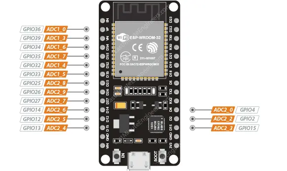
The ADC on the ESP32 operates as a 12-bit ADC, enabling it to detect 4096 discrete analog levels. In simpler terms, it converts input voltages within the range of 0 to 3.3V (the operating voltage) into integer values ranging from 0 to 4095. This equates to a resolution of 3.3 volts divided by 4096 units, which equals 0.0008 volts (0.8 mV) per unit.
Additionally, the ADC resolution and channel range can be adjusted programmatically to suit specific requirements.
When the Wi-Fi functionality is enabled, the ADC2 pins cannot be utilized. If your project necessitates the use of Wi-Fi, it is advisable to utilize the ADC1 pins instead.
DAC Pins
The ESP32 is equipped with two 8-bit DAC (Digital-to-Analog Converter) channels designed for converting digital signals into true analog voltages. These DAC channels can be utilized as a “digital potentiometer” to control analog devices.
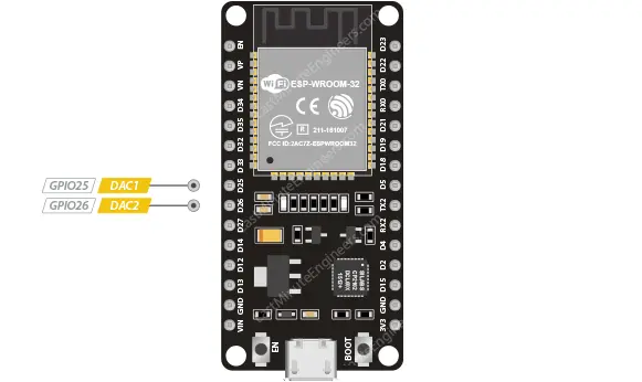
The DACs on the ESP32 offer an 8-bit resolution, meaning that values ranging from 0 to 256 will be converted to an analog voltage range of 0 to 3.3V.
Touch Pins
The ESP32 features 9 GPIOs specifically designed for capacitive touch sensing. When a capacitive load, such as a human finger, is in close proximity to these GPIOs, the ESP32 detects the change in capacitance.
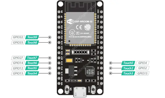
These touch pins offer the flexibility to create touch pads by attaching various conductive objects like aluminum foil, conductive cloth, conductive paint, and more. The circuit’s low-noise design and high sensitivity allow for the creation of relatively small touch pads.
Furthermore, these capacitive touch pins can also serve the purpose of waking the ESP32 from deep sleep, providing an additional functionality beyond touch sensing.
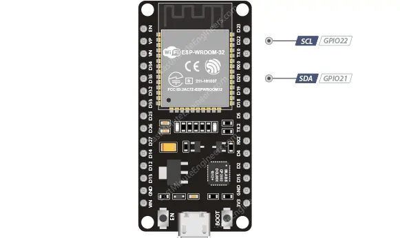
I2C Pins
The ESP32 provides a single I2C bus, which enables you to connect a wide range of sensors and peripherals, totaling up to 112 devices. By default, the SDA (Serial Data Line) and SCL (Serial Clock Line) pins are assigned as follows. However, if needed, you can use the wire.begin(SDA, SCL) command to utilize any GPIO pins for bit-banging the I2C protocol.
SPI Pins
The ESP32 is equipped with three SPIs (SPI, HSPI, and VSPI) that can operate in both slave and master modes. These SPI interfaces offer support for various general-purpose SPI features, including:
- 4 timing modes for SPI format transfer
- Clock frequencies of up to 80 MHz, with the ability to use divided clocks of 80 MHz
- Up to 64-byte FIFO (First-In-First-Out) buffer for efficient data transfer
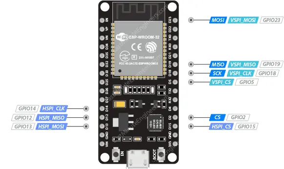
Among the three SPI buses, only HSPI and VSPI are available for use as SPI interfaces. The third SPI bus is dedicated to the integrated flash memory chip. Typically, VSPI pins are commonly utilized in standard libraries.
It’s worth noting that HSPI is sometimes mistaken for “Hardware” SPI, while VSPI is seen as “Virtual” or “Software” SPI. However, in reality, both HSPI and VSPI are functionally identical.
Similar to I2C, if necessary, you can also bit-bang the SPI protocol on any GPIO pins using the bus.begin(CLK_PIN, MISO_PIN, MOSI_PIN, SS_PIN); command.
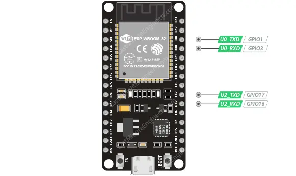
UART Pins
The ESP32 development board features three UART interfaces: UART0, UART1, and UART2. These interfaces support asynchronous communication protocols such as RS232, RS485, and IrDA, with a maximum data rate of 5 Mbps.
It’s important to note that UART0 pins are directly connected to the USB-to-Serial converter, making them primarily used for flashing firmware and debugging purposes. Consequently, it is not recommended to utilize UART0 pins for general communication needs.
UART1 pins are reserved for the integrated flash memory chip and are not accessible for other purposes.
On the other hand, UART2 is a viable and safe option for connecting UART devices like GPS modules, fingerprint sensors, distance sensors, and similar peripherals.
Furthermore, UART interfaces offer hardware management of Clear To Send (CTS) and Request To Send (RTS) signals, as well as software flow control using XON and XOFF protocols.
PWM Pins
The ESP32 development board provides a total of 21 channels for Pulse Width Modulation (PWM) signals. These channels correspond to all available GPIOs except for input-only GPIOs. The PWM pins are controlled by a PWM controller and can be utilized for various applications, including driving digital motors and LEDs.
The PWM controller consists of PWM timers, a PWM operator, and a dedicated capture sub-module. Each timer offers timing in synchronous or independent form, while each PWM operator generates a waveform for a specific PWM channel. The dedicated capture sub-module allows precise event capturing with external timing.
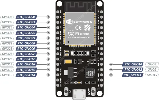
RTC GPIO Pins
Certain GPIOs are routed to the RTC (Real-Time Clock) low-power subsystem and are known as RTC GPIOs. These pins serve as wake-up sources for the ESP32 when it is in deep sleep mode and the Ultra Low Power (ULP) co-processor is active. The GPIOs highlighted in the documentation can be utilized as external wake-up sources.
Strapping Pins
There are five strapping pins on the ESP32 board: GPIO0, GPIO2, GPIO5, GPIO12, and GPIO15.
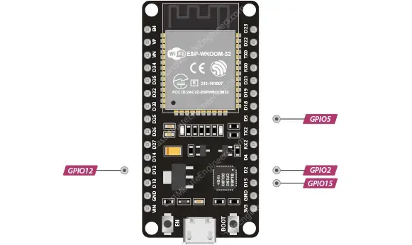
These pins are responsible for determining whether the ESP32 enters BOOT mode (to run the program stored in flash memory) or FLASH mode (to upload new programs or firmware). Depending on the state of these pins during power-on, the ESP32 will automatically enter the appropriate mode.
On most development boards with built-in USB/Serial, the state of these pins is managed automatically, so users don’t need to worry about manually setting them for flashing or boot mode. However, when external peripherals are connected to these pins, it may lead to issues during code uploading or firmware flashing, as these peripherals can prevent the ESP32 from entering the correct mode.
While the strapping pins operate normally after the reset release, caution should still be exercised when working with them.
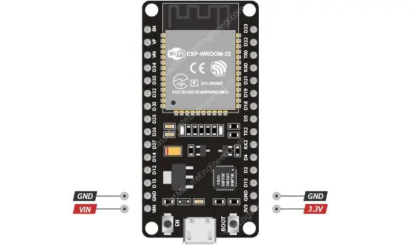
Power Pins
There are two power pins on the ESP32 board: VIN and 3V3. The VIN pin can be used to directly power the ESP32 and its peripherals if you have a regulated 5V power supply. The 3V3 pin provides a regulated output from the on-board voltage regulator, offering up to 600mA. GND serves as the ground pin.
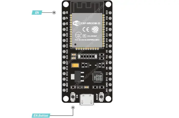
Enable Pin
The EN pin serves as the enable pin for the ESP32 and is pulled high by default. When the EN pin is pulled HIGH, the chip is enabled, and when it is pulled LOW, the chip is disabled.
The EN pin is also connected to a pushbutton switch that can be used to pull the pin LOW and trigger a reset of the ESP32.
Related article
- Essential ESP32 ADC Basics: Analog-to-Digital Converter Explained
- ESP32 Capacitive Touch Pins: Basics for Interactive Projects
- Step-by-Step Tutorial: Setting Up ESP32 Board in Arduino IDE


