
A Force Sensing Resistor (FSR), also referred to as a Force Sensor, is a cost-effective and straightforward sensor specifically designed to measure physical pressure, squeezing, and weight.
FSRs are commonly found in various portable electronic devices such as electronic drums, handheld gaming devices, and mobile phones.
While this sensor excels at measuring pressure, it may not provide highly accurate weight estimation. However, if your objective is to determine whether the sensor has been squeezed or pressed and the intensity of the applied force, an FSR can be a suitable option for your next force-sensing project.
FSR Overview
FSRs utilize patented technology owned by Interlink Electronics, a company established in 1985. The commonly encountered FSR types are Interlink FSR-402 and FSR-406.
Construction
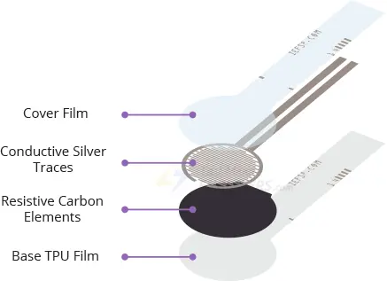
An FSR is essentially a variable resistor that changes its resistance in response to applied pressure on its sensing area.
It consists of multiple thin and flexible layers. When pressure is applied, more carbon elements come into contact with the conductive traces, resulting in a decrease in resistance.
Shape and Size
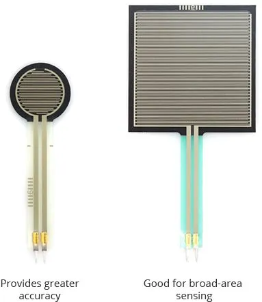
FSRs are available in various shapes, sizes, and sensing ranges to suit different applications.
Circular or rectangular sensing areas are commonly found in FSRs. Rectangular FSRs are well-suited for wide-area sensing, while smaller circular sensors offer higher accuracy.
Sensing Range
The sensing range of an FSR is a crucial factor as it determines the minimum and maximum pressures it can detect.
A shorter sensing range results in higher sensitivity. However, pressures beyond the maximum range of the sensor cannot be measured (and may even damage the sensor). For example, a smaller FSR rated for 1kg will provide more sensitive readings from 0 to 1kg, but it won’t differentiate between 2kg and 5kg.
How Does FSR Work?
An FSR operates by changing its resistive value in response to applied pressure.
When there is no pressure applied, the sensor’s resistance is extremely high (greater than 1MΩ). As pressure is applied to the sensor’s surface, the resistance between its terminals decreases. Releasing the pressure causes the resistance to return to its original value.
The graph below illustrates the approximate resistance characteristics of the FSR-402 sensor at different applied forces. Logarithmic scales are used in the graph representation.
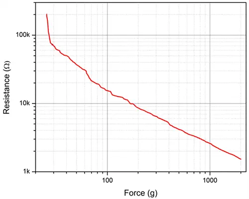
It can be observed that the graph shows a linear relationship above 50g. This behavior is due to the presence of a turn-on threshold in these sensors. A certain force must be exerted to lower the resistance below 100kΩ, after which the relationship becomes more linear.
Reading an FSR
To read the FSR, a common approach is to create a voltage divider circuit by combining it with a static resistor. This configuration generates a variable voltage that can be measured by the analog-to-digital converter of a microcontroller.
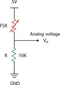
It’s important to understand that the measured output voltage is the voltage drop across the pull-down resistor, not the voltage drop across the FSR itself.
The following equation can be used to calculate the output voltage (Vo):
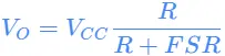
In this setup, the output voltage increases as the applied force on the FSR increases.
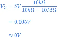
For instance, when a 5V supply and a 10K pull-down resistor are used, the FSR resistance is very high (around 10MΩ) when no pressure is applied. This results in the following output voltage:
When significant force is applied to the FSR and its resistance drops to around 250Ω, the output voltage becomes:
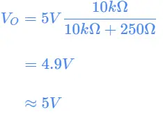
As illustrated, the output voltage ranges from 0V to 5V depending on the magnitude of the applied force on the sensor.
The table below provides a general indication of the analog voltage you can expect from an FSR at different levels of applied force.
| Force (lb) | Force (N) | FSR Resistance | Voltage across R |
| None | None | Infinite | 0V |
| 0.04lb | 0.2N | 30KΩ | 1.3V |
| 0.22lb | 1N | 6KΩ | 3.1V |
| 2.2lb | 10N | 1KΩ | 4.5V |
| 22lb | 100N | 250Ω | 4.9V |
Wiring an FSR to an Arduino
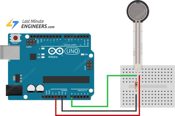
Connecting an FSR to an Arduino is a straightforward process.
Start by connecting a 10kΩ pull-down resistor in series with the FSR to create a voltage divider circuit. Then, wire the A0 analog input of the Arduino to the junction point between the pull-down resistor and the FSR.
Parts Required
| Component Name | Buy Now |
| Arduino Uno REV3 | Amazon |
| Thin Film Pressure Sensor 20g-2Kg DF9-16 High Precise Force Sensitive Resistor Force Sensor | Amazon |
| Breadboard | Amazon |
| BOJACK 1000 Pcs 25 Values Resistor Kit 1 Ohm-1M Ohm with 5% 1/4W | Amazon |
Arduino Example 1 – Simple Analog FSR Measurements
In our initial experiment, we will retrieve sensor data from the Arduino’s ADC pin and display it on the serial monitor.
The code is straightforward and provides a qualitative representation of the pressure sensed by the FSR. This is typically sufficient for most projects.
int fsrPin = 0;     // the FSR and 10K pulldown are connected to a0
int fsrReading;     // the analog reading from the FSR resistor divider

void setup(void) {
  Serial.begin(9600);
}

void loop(void) {
  fsrReading = analogRead(fsrPin);

  Serial.print("Analog reading = ");
  Serial.print(fsrReading);     // print the raw analog reading

  if (fsrReading < 10) {
    Serial.println(" - No pressure");
  } else if (fsrReading < 200) {
    Serial.println(" - Light touch");
  } else if (fsrReading < 500) {
    Serial.println(" - Light squeeze");
  } else if (fsrReading < 800) {
    Serial.println(" - Medium squeeze");
  } else {
    Serial.println(" - Big squeeze");
  }
  delay(1000);
}
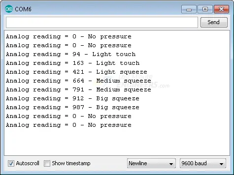
If everything is functioning correctly, you should observe the following output on the serial monitor.
Code Explanation:
The sketch starts by defining the Arduino pin to which the FSR is connected and the variable fsrReading to store the FSR’s analog reading.
int fsrPin = 0;
int fsrReading;
In the setup function, serial communication is initialized.
void setup(void) {
  Serial.begin(9600);
}
In the loop function, the FSR’s analog output is read using the analogRead function and stored in fsrReading.
fsrReading = analogRead(fsrPin);
The fsrReading value is then printed on the serial monitor to display the raw analog reading.
Serial.print("Analog reading = ");
Serial.print(fsrReading);
Based on the fsrReading value, a qualitative description of the pressure is printed using if-else statements.
if (fsrReading < 10) {
  Serial.println(" - No pressure");
} else if (fsrReading < 200) {
  Serial.println(" - Light touch");
} else if (fsrReading < 500) {
  Serial.println(" - Light squeeze");
} else if (fsrReading < 800) {
  Serial.println(" - Medium squeeze");
} else {
  Serial.println(" - Big squeeze");
}
A delay of 1 second is added using delay(1000) to pause between readings.
Overall, the code reads the FSR’s analog output, displays it on the serial monitor, and provides a qualitative interpretation of the pressure sensed by the FSR.
Arduino Example 2 – Advanced Analog FSR Measurements
The following Arduino sketch is quite advanced. It measures the approximate Newton force measured by the FSR. This can be quite helpful for calibrating the forces you expect the FSR will experience.
int fsrPin = 0;     // the FSR and 10K pulldown are connected to a0
int fsrReading;     // the analog reading from the FSR resistor divider
int fsrVoltage;     // the analog reading converted to voltage
unsigned long fsrResistance;  // The voltage converted to resistance
unsigned long fsrConductance;
long fsrForce;       // Finally, the resistance converted to force

void setup(void) {
  Serial.begin(9600);   // We'll send debugging information via the Serial monitor
}

void loop(void) {
  fsrReading = analogRead(fsrPin);
  Serial.print("Analog reading = ");
  Serial.println(fsrReading);

  // analog voltage reading ranges from about 0 to 1023 which maps to 0V to 5V (= 5000mV)
  fsrVoltage = map(fsrReading, 0, 1023, 0, 5000);
  Serial.print("Voltage reading in mV = ");
  Serial.println(fsrVoltage);

  if (fsrVoltage == 0) {
    Serial.println("No pressure");
  } else {
    // The voltage = Vcc * R / (R + FSR) where R = 10K and Vcc = 5V
    // so FSR = ((Vcc - V) * R) / V        yay math!
    fsrResistance = 5000 - fsrVoltage;     // fsrVoltage is in millivolts so 5V = 5000mV
    fsrResistance *= 10000;                // 10K resistor
    fsrResistance /= fsrVoltage;
    Serial.print("FSR resistance in ohms = ");
    Serial.println(fsrResistance);

    fsrConductance = 1000000;           // we measure in micromhos so
    fsrConductance /= fsrResistance;
    Serial.print("Conductance in microMhos: ");
    Serial.println(fsrConductance);

    // Use the two FSR guide graphs to approximate the force
    if (fsrConductance <= 1000) {
      fsrForce = fsrConductance / 80;
      Serial.print("Force in Newtons: ");
      Serial.println(fsrForce);
    } else {
      fsrForce = fsrConductance - 1000;
      fsrForce /= 30;
      Serial.print("Force in Newtons: ");
      Serial.println(fsrForce);
    }
  }
  Serial.println("--------------------");
  delay(1000);
}
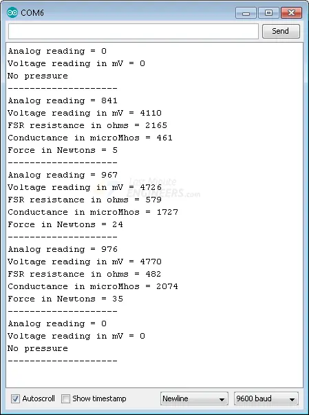
Here’s what the output looks like in the serial monitor.
Code Explanation:
The code starts by declaring the necessary variables for reading and calculating the FSR force.
int fsrPin = 0;
int fsrReading;
int fsrVoltage;
unsigned long fsrResistance;
unsigned long fsrConductance;
long fsrForce;
In the setup function, serial communication is initialized.
void setup(void) {
  Serial.begin(9600);
}
The loop function reads the analog output of the FSR using analogRead and converts it to voltage using the map function.
fsrReading = analogRead(fsrPin);
fsrVoltage = map(fsrReading, 0, 1023, 0, 5000);
The FSR resistance is then calculated based on the voltage using the given formula. The conductance is calculated as the reciprocal of the resistance.
fsrResistance = 5000 - fsrVoltage;
fsrResistance *= 10000;
fsrResistance /= fsrVoltage;

fsrConductance = 1000000;
fsrConductance /= fsrResistance;
Based on the conductance value, the force is approximated using the provided guide graphs.
if (fsrConductance <= 1000) {
  fsrForce = fsrConductance / 80;
  Serial.print("Force in Newtons: ");
  Serial.println(fsrForce);
} else {
  fsrForce = fsrConductance - 1000;
  fsrForce /= 30;
  Serial.print("Force in Newtons: ");
  Serial.println(fsrForce);
}
The measured analog reading, voltage, FSR resistance, and force are printed on the serial monitor.
A delay of 1 second is added using delay(1000) to pause between readings.
The code provides advanced measurement of the force using the FSR by calculating resistance, conductance, and approximating the force in Newtons based on the given formulas and guide graphs.
Related article
- Interfacing TTP223 Touch Sensor with Arduino: Step-by-Step Guide
- Arduino RFID Tutorial: Interface RC522 RFID Module and How It Works
- Step-by-Step Guide: HC-SR501 PIR Sensor Working Principles and Arduino Integration
- Understanding the Operation of HC-SR04 Ultrasonic Sensor and Connecting it to Arduino


