

Arduino Uno and other microcontrollers come with a built-in Analog to Digital Converter (ADC) that can convert analog voltages to digital values. However, there is a maximum limit of 5V for the analog input pin voltage. This limitation can be inconvenient if you need to measure voltages higher than 5V. One solution is to create a voltage divider using discrete resistors, but there’s an easier option available: using a Voltage Sensor.
A Voltage Sensor is a ready-made voltage divider circuit that employs precision resistors to provide accurate voltage readings. It is particularly useful for measuring voltages below 25V. By utilizing a voltage sensor, you can simplify and enhance the efficiency of your voltage measurement tasks when working with an Arduino.
In this tutorial, we will explore how to effectively use a voltage sensor with an Arduino, enabling you to streamline your voltage measurement projects. Let’s dive in and get started!
Hardware Overview
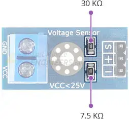
The Voltage Sensor is a straightforward voltage divider circuit that consists of two resistors, without any complex components.
The schematic diagram of the Voltage Sensor is depicted in the image below.
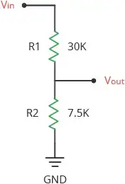
This circuit includes two resistors: R1, which is positioned closest to the input voltage, has a value of 30 KΩ, and R2, located closer to ground, has a value of 7.5 KΩ. The voltage drop across R2 serves as our divided voltage. This signal is accessible through a header pin labeled S.
By employing this uncomplicated circuit, the input voltage is divided by a factor of 5. As a result, the voltage sensor allows for the measurement of voltages below 25 volts using an Arduino.
Reading the Voltage Sensor
Measuring the voltage of a voltage sensor or any voltage divider is a straightforward process. We can utilize the voltage divider equation to determine the input voltage based on known circuit values.
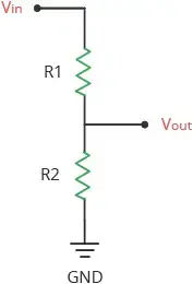
The voltage divider equation assumes that you are aware of three values: the input voltage (Vin) and the resistor values (R1 and R2) in the circuit. With these values, we can calculate the output voltage (Vout) using the equation:
Vout = Vin * (R2 / (R1 + R2))
In our scenario, our goal is to measure the output voltage (Vout) using Arduino’s ADC. Consequently, the value we need to determine is Vin, which represents the input voltage.
To solve for Vin, we can rearrange the equation:
Vin = Vout * (R1 + R2) / R2
This equation unveils that the input voltage (Vin) can be obtained by multiplying the output voltage (Vout) by the ratio of the sum of the resistances (R1 + R2) to the resistance (R2) in the circuit.
Voltage Sensor Pinout
Let’s take a look at the pinout of the voltage sensor:
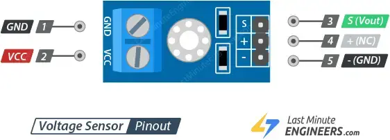
Input Terminal:
VCC: This pin is connected to the positive terminal of the voltage source you want to measure. It should be within the recommended voltage range of 0 to 25V.
GND: This pin is connected to the negative terminal of the input voltage source.
Output Header:
S: The S pin is the signal output pin of the voltage sensor module. It provides an analog voltage output that is proportional to the input voltage level. Typically, this pin is connected to one of the analog input pins on the Arduino.
+: The + pin is not connected to anything.
-: The – pin is the common ground pin.
Hardware Hookup
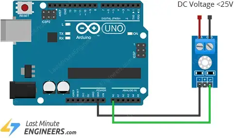
Connecting a voltage sensor to an Arduino is a simple process. Follow these steps:
- Connect the positive terminal of the voltage source you want to measure to the input screw terminal of the voltage sensor.
- Connect the ‘S’ pin of the voltage sensor to the ‘A0’ analog pin on the Arduino.
- Connect the ‘-‘ pin of the voltage sensor to the ground (GND) pin on the Arduino.
Refer to the image below for a visual representation of the connections.
Parts Required
| Component Name | Buy Now |
| Arduino Uno REV3 | Amazon |
| Voltage Tester Sensor Measurement Detection Module DC 0-25V Terminal | Amazon |
| Breadboard | Amazon |
| BOJACK 1000 Pcs 25 Values Resistor Kit 1 Ohm-1M Ohm with 5% 1/4W | Amazon |
Arduino Example Code
Here is a simple Arduino sketch that reads the analog voltage from pin A0, calculates the input voltage using the voltage divider equation, and displays the results in the Serial Monitor.
// Define analog input
#define ANALOG_IN_PIN A0

// Floats for ADC voltage & Input voltage
float adc_voltage = 0.0;
float in_voltage = 0.0;

// Floats for resistor values in divider (in ohms)
float R1 = 30000.0;
float R2 = 7500.0;

// Float for Reference Voltage
float ref_voltage = 5.0;

// Integer for ADC value
int adc_value = 0;

void setup(){
  // Setup Serial Monitor
  Serial.begin(9600);
}

void loop(){
  // Read the Analog Input
  adc_value = analogRead(ANALOG_IN_PIN);

  // Determine voltage at ADC input
  adc_voltage  = (adc_value * ref_voltage) / 1024.0;

  // Calculate voltage at divider input
  in_voltage = adc_voltage*(R1+R2)/R2;

  // Print results to Serial Monitor to 2 decimal places
  Serial.print("Input Voltage = ");
  Serial.println(in_voltage, 2);

  // Short delay
  delay(500);
}
Upload the sketch to your Arduino and observe the results in the Serial Monitor.
To verify the accuracy, measure the actual voltage using a digital multimeter. The displayed value on the multimeter should match the reading shown on the Serial Monitor.
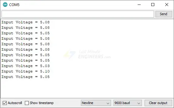
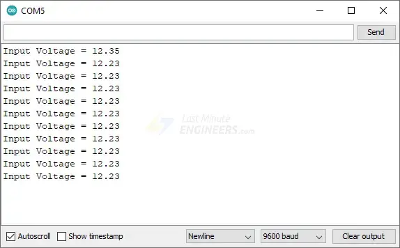
The following results are obtained when applying 5V and 12V to the voltage sensor, respectively:
- Input Voltage = 5.00
- Input Voltage = 11.86
Code Explanation:
This sketch is straightforward and easy to understand. It begins by defining global variables that will be used throughout the program.
The analog input pin used to read the voltage from the voltage divider circuit is defined as A0.
#define ANALOG_IN_PIN A0
Two float variables, adc_voltage and in_voltage, are initialized to store the voltage readings at the ADC and the input of the voltage divider, respectively.
float adc_voltage = 0.0;
float in_voltage = 0.0;
R1 and R2 store the resistance values of the voltage divider. Adjust these values according to your own voltage divider configuration.
float R1 = 30000.0;
float R2 = 7500.0;
The reference voltage for the ADC is set to 5V.
float ref_voltage = 5.0;
adc_value is an integer variable used to store the raw digital value read from the ADC.
int adc_value = 0;
In the setup(), the serial communication is initialized at a baud rate of 9600.
void setup(){
  Serial.begin(9600);
}
In the loop(), the analogRead() function is used to read the voltage on pin A0. The obtained value is stored in adc_value.
adc_value = analogRead(ANALOG_IN_PIN);
This value is then converted to a voltage (adc_voltage) by multiplying it with the reference voltage and dividing it by 1024 (as the Arduino has a 10-bit ADC).
adc_voltage = (adc_value * ref_voltage) / 1024.0;
The input voltage to the voltage divider (in_voltage) is calculated using the voltage divider formula.
in_voltage = adc_voltage*(R1+R2)/R2;
The calculated input voltage is then printed to the Serial Monitor, displaying up to 2 decimal places. After that, the Arduino waits for 500 milliseconds before repeating the loop.
Serial.print("Input Voltage = ");
Serial.println(in_voltage, 2);

delay(500);
Related article
- MAX4466 Microphone Module: Arduino Interface Guide
- MAX6675 Thermocouple Module: Seamless Integration with Arduino
- Step-by-Step: Connecting Reed Switch to Arduino
- Arduino Water Quality Testing: Utilizing the TDS Sensor


