
So, you’re trying to upload a new sketch to your ESP32 but keep getting the error message “A fatal error occurred: Failed to connect to ESP32: Timed out waiting for packet header”? That’s frustrating! But don’t worry, I can help you understand why this error happens and how to fix it.
Parts Required
| Component Name | Buy Now |
| ESP32-WROOM-32 Development | Amazon |
Understanding the Error
Some ESP32 boards automatically enter flashing/uploading mode, allowing the sketch to be uploaded without issues. However, others might not, resulting in the error mentioned above.
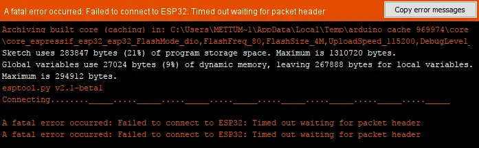
This error typically occurs during the initial boot sequence when the computer tries but fails to establish a communication link with the ESP32.
The “packet header” is the first part of the data packet the computer expects from the ESP32, containing crucial information for data transfer. A timeout means the computer didn’t receive this packet within the expected time frame.
When Does This Error Occur?
You might encounter this error due to several reasons:
- Driver Issues: Outdated USB drivers can lead to communication problems.
- Connection Issues: A faulty USB cable or loose connection can disrupt communication between the computer and the ESP32.
- PCB Design Flaws: Poorly designed development boards may cause this issue.
- Failure to Enter Flashing Mode: The ESP32 must be in flashing/uploading mode to upload a new sketch. If it isn’t, the device won’t respond correctly.
How to Fix the Error
Update USB Drivers
The ESP32 uses a USB-to-Serial chip to communicate with the computer during the sketch upload process. If the drivers for this chip are outdated, the computer might not communicate with the ESP32 properly, causing the error. Identify the USB-to-Serial chip on your ESP32 board (such as CH340, CP210x, or FTDI) and ensure you have the latest drivers installed. Sometimes, simply uninstalling and reinstalling the drivers can solve the issue.
Check the USB Cable
A stable connection is crucial when uploading code to the ESP32. A faulty cable or loose connection can interrupt the process, causing the computer to miss data packets from the ESP32. Use a high-quality USB cable, securely connect it to both the computer and the ESP32, and avoid using USB hubs or extenders. Also, ensure the cable supports data transfer, as some cables are only meant for charging.
Disconnect Peripherals
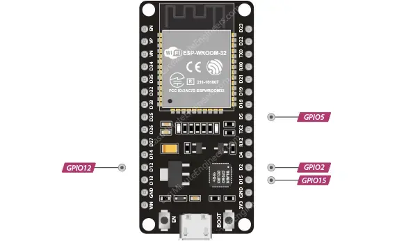
Peripherals connected to the strapping pins (GPIO0, GPIO2, GPIO5, GPIO12, and GPIO15) might prevent the ESP32 from entering the correct mode, causing the error. Disconnect any peripherals from these pins during the flashing process.
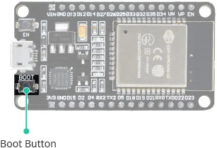
Hold the Boot Button
If the error persists despite updated drivers, a good USB cable, and no connected peripherals, you can manually force the ESP32 into flashing mode. Here’s how:
- Press the Upload button in the Arduino IDE to start uploading a new sketch.
- When you see the “Connecting…” message (or just before), press and hold the BOOT button on the ESP32.
- Release the BOOT button once the “Writing at…” message appears, indicating the upload has started.
Repeat this process each time you upload a new sketch. For a more permanent solution, continue reading.
Solder a 10uF Electrolytic Capacitor
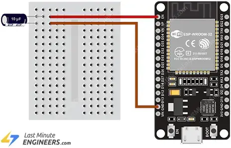
To ensure the ESP32 automatically enters flashing mode, you can solder a 10 uF electrolytic capacitor between the EN (enable) pin and the GND (ground) pin. This helps by delaying the voltage change, ensuring a stable reset and giving the computer enough time to establish a connection. Follow these steps:
- Disconnect the ESP32 from your computer.
- Insert a 10 uF electrolytic capacitor into a breadboard. Note the polarity—the longer leg is positive, and a stripe on the side marks the negative leg.
- Connect the positive leg to the EN pin and the negative leg to a GND pin on the ESP32.
- Reconnect the ESP32 to your computer and try uploading a sketch again.
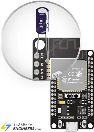
If this works, you can solder the capacitor directly onto the board. Connect the capacitor between the EN pin and the first GND pin of the ESP32-WROOM-32 module, being careful to avoid shorting adjacent pins.
Did You Successfully Upload the Sketch?
The “Failed to Connect to ESP32” error can be frustrating, but it’s usually solvable with some troubleshooting. Hopefully, one of these solutions worked for you, and you were able to upload the sketch without issues. If you’re still experiencing problems, don’t be discouraged; just spend some more time troubleshooting.
Related article
- How to Assign a Fixed IP Address to Your ESP32 Device
- Learn How to Set Up mDNS on ESP32 in Minutes
- ESP32 vs. ESP8266: Which Microcontroller Fits Your Requirements?
- Firebase Authentication with ESP32/ESP8266: Email and Password Guide
- Node-RED & MQTT with ESP8266: Easy Publish and Subscribe Tutorial


