

This tutorial teaches you how to construct an asynchronous web server using the ESP8266 NodeMCU board for managing its outputs. Arduino IDE will be utilized for programming the board, and we’ll employ the ESPAsyncWebServer library.
Creating an Asynchronous Web Server
For constructing the web server, we’ll utilize the ESPAsyncWebServer library, offering a straightforward method to develop an asynchronous web server. Building an asynchronous web server holds numerous benefits outlined on the library’s GitHub page, including:
- Managing multiple connections simultaneously.
- Immediate readiness to handle other connections upon sending a response, while the server processes sending the response in the background.
- Incorporating a simple template processing engine for template handling.
- Plus many additional features.
Refer to the library documentation available on its GitHub page for further details.
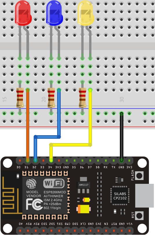
Schematic
Before delving into the code, connect three LEDs to the ESP8266 async web server. We’re wiring the LEDs to GPIOs 5, 4, and 2, although you have the flexibility to use any other GPIOs
Installing Libraries – ESP Async Web Server
For setting up the web server, you’ll need to install the following libraries. Click on the links below to download them.
These libraries aren’t accessible via the Arduino Library Manager, so you’ll have to manually copy the library files to the Arduino Installation Libraries folder. Alternatively, within your Arduino IDE, navigate to Sketch > Include Library > Add .zip Library, and choose the libraries you’ve recently downloaded.
Project Overview
To gain a deeper comprehension of the code, let’s explore the functionality of the web server.
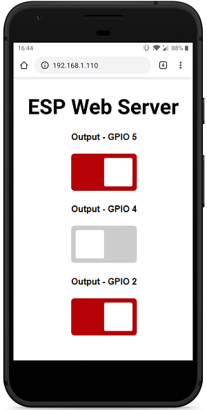
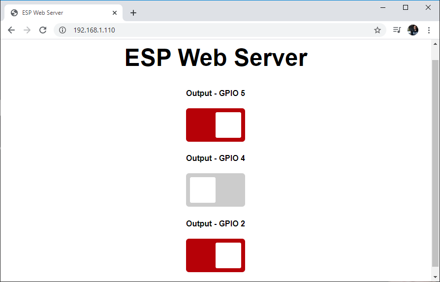
The web server consists of a single header titled “ESP Web Server” and three buttons (toggle switches) for controlling three outputs. Each button is labeled with the corresponding GPIO output pin. Additional outputs can be easily added or removed.
When a button appears red, it indicates that the output is active (its state is HIGH). Toggling the button switches off the output (changing its state to LOW).
Conversely, when a button appears gray, it signifies that the output is inactive (its state is LOW). Toggling the button switches on the output (changing its state to HIGH).
How it Works?
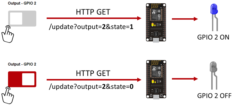
Let’s examine the process when toggling the buttons. We’ll illustrate the example for GPIO 2, although the operation is analogous for the other buttons.
- In the first scenario, toggling the button activates GPIO 2. This triggers an HTTP GET request to the /update?output=2&state=1 URL. Based on this URL, the state of GPIO 2 is changed to 1 (HIGH), illuminating the LED.
- In the second scenario, toggling the button deactivates GPIO 2. This initiates an HTTP GET request to the /update?output=2&state=0 URL. Based on this URL, the state of GPIO 2 is changed to 0 (LOW), turning off the LED.
Code for ESP Async Web Server
Copy the following code to your Arduino IDE.
// Import required libraries
#include <ESP8266WiFi.h>
#include <ESPAsyncTCP.h>
#include <ESPAsyncWebServer.h>

// Replace with your network credentials
const char* ssid = "REPLACE_WITH_YOUR_SSID";
const char* password = "REPLACE_WITH_YOUR_PASSWORD";

const char* PARAM_INPUT_1 = "output";
const char* PARAM_INPUT_2 = "state";

// Create AsyncWebServer object on port 80
AsyncWebServer server(80);

const char index_html[] PROGMEM = R"rawliteral(
<!DOCTYPE HTML><html>
<head>
  <title>ESP Web Server</title>
  <meta name="viewport" content="width=device-width, initial-scale=1">
  <link rel="icon" href="data:,">
  <style>
    html {font-family: Arial; display: inline-block; text-align: center;}
    h2 {font-size: 3.0rem;}
    p {font-size: 3.0rem;}
    body {max-width: 600px; margin:0px auto; padding-bottom: 25px;}
    .switch {position: relative; display: inline-block; width: 120px; height: 68px}
    .switch input {display: none}
    .slider {position: absolute; top: 0; left: 0; right: 0; bottom: 0; background-color: #ccc; border-radius: 6px}
    .slider:before {position: absolute; content: ""; height: 52px; width: 52px; left: 8px; bottom: 8px; background-color: #fff; -webkit-transition: .4s; transition: .4s; border-radius: 3px}
    input:checked+.slider {background-color: #b30000}
    input:checked+.slider:before {-webkit-transform: translateX(52px); -ms-transform: translateX(52px); transform: translateX(52px)}
  </style>
</head>
<body>
  <h2>ESP Web Server</h2>
  %BUTTONPLACEHOLDER%
<script>function toggleCheckbox(element) {
  var xhr = new XMLHttpRequest();
  if(element.checked){ xhr.open("GET", "/update?output="+element.id+"&state=1", true); }
  else { xhr.open("GET", "/update?output="+element.id+"&state=0", true); }
  xhr.send();
}
</script>
</body>
</html>
)rawliteral";

// Replaces placeholder with button section in your web page
String processor(const String& var){
  //Serial.println(var);
  if(var == "BUTTONPLACEHOLDER"){
    String buttons = "";
    buttons += "<h4>Output - GPIO 5</h4><label class=\"switch\"><input type=\"checkbox\" onchange=\"toggleCheckbox(this)\" id=\"5\" " + outputState(5) + "><span class=\"slider\"></span></label>";
    buttons += "<h4>Output - GPIO 4</h4><label class=\"switch\"><input type=\"checkbox\" onchange=\"toggleCheckbox(this)\" id=\"4\" " + outputState(4) + "><span class=\"slider\"></span></label>";
    buttons += "<h4>Output - GPIO 2</h4><label class=\"switch\"><input type=\"checkbox\" onchange=\"toggleCheckbox(this)\" id=\"2\" " + outputState(2) + "><span class=\"slider\"></span></label>";
    return buttons;
  }
  return String();
}

String outputState(int output){
  if(digitalRead(output)){
    return "checked";
  }
  else {
    return "";
  }
}

void setup(){
  // Serial port for debugging purposes
  Serial.begin(115200);

  pinMode(5, OUTPUT);
  digitalWrite(5, LOW);
  pinMode(4, OUTPUT);
  digitalWrite(4, LOW);
  pinMode(2, OUTPUT);
  digitalWrite(2, LOW);

  // Connect to Wi-Fi
  WiFi.begin(ssid, password);
  while (WiFi.status() != WL_CONNECTED) {
    delay(1000);
    Serial.println("Connecting to WiFi..");
  }

  // Print ESP Local IP Address
  Serial.println(WiFi.localIP());

  // Route for root / web page
  server.on("/", HTTP_GET, [](AsyncWebServerRequest *request){
    request->send_P(200, "text/html", index_html, processor);
  });

  // Send a GET request to <ESP_IP>/update?output=<inputMessage1>&state=<inputMessage2>
  server.on("/update", HTTP_GET, [] (AsyncWebServerRequest *request) {
    String inputMessage1;
    String inputMessage2;
    // GET input1 value on <ESP_IP>/update?output=<inputMessage1>&state=<inputMessage2>
    if (request->hasParam(PARAM_INPUT_1) && request->hasParam(PARAM_INPUT_2)) {
      inputMessage1 = request->getParam(PARAM_INPUT_1)->value();
      inputMessage2 = request->getParam(PARAM_INPUT_2)->value();
      digitalWrite(inputMessage1.toInt(), inputMessage2.toInt());
    }
    else {
      inputMessage1 = "No message sent";
      inputMessage2 = "No message sent";
    }
    Serial.print("GPIO: ");
    Serial.print(inputMessage1);
    Serial.print(" - Set to: ");
    Serial.println(inputMessage2);
    request->send(200, "text/plain", "OK");
  });

  // Start server
  server.begin();
}

void loop() {

}
How the Code Works
This section elucidates the functionality of the code. Continue reading to delve deeper into its workings, or proceed to the Demonstration section to witness the final outcome.
Importing libraries
Begin by importing the necessary libraries. You’ll need to include the WiFi, ESPAsyncWebserver, and ESPAsyncTCP libraries.
#include <ESP8266WiFi.h>
#include <ESPAsyncTCP.h>
#include <ESPAsyncWebServer.h>
Setting Network Credentials
Input your network credentials into the following variables to enable the ESP8266 async web server to connect to your local network.
const char* ssid = "REPLACE_WITH_YOUR_SSID";
const char* password = "REPLACE_WITH_YOUR_PASSWORD";
Input Parameters
To inspect the parameters passed through the URL (GPIO number and its state), two variables are created, one for the output and the other for the state.
const char* PARAM_INPUT_1 = "output";
const char* PARAM_INPUT_2 = "state";
Remember that the ESP8266 receives requests in this format: /update?output=2&state=0.
AsyncWebServer object
Instantiate an AsyncWebServer object on port 80.
AsyncWebServer server(80);
Constructing the Web Page
The entire HTML content with styles and JavaScript resides within the index_html variable. Let’s dissect the HTML content to understand its components.
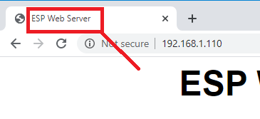
The title enclosed within the <title> tags defines the title of the document, visible in the web browser’s title bar. In this instance, it’s set to “ESP Web Server”.
<title>ESP Web Server</title>
The subsequent <meta> tag ensures responsiveness across various browsers, such as laptops, tablets, or smartphones.
<meta name="viewport" content="width=device-width, initial-scale=1">
The subsequent line prevents requests for the favicon. Since we don’t have a favicon in this case, adding this line helps avoid unnecessary requests.
<link rel="icon" href="data:,">
Within the <style></style> tags, CSS is employed to style the web page. Detailed explanation of the CSS styling is omitted here.
<style>
    html {font-family: Arial; display: inline-block; text-align: center;}
    h2 {font-size: 3.0rem;}
    p {font-size: 3.0rem;}
    body {max-width: 600px; margin:0px auto; padding-bottom: 25px;}
    .switch {position: relative; display: inline-block; width: 120px; height: 68px}
    .switch input {display: none}
    .slider {position: absolute; top: 0; left: 0; right: 0; bottom: 0; background-color: #ccc; border-radius: 6px}
    .slider:before {position: absolute; content: ""; height: 52px; width: 52px; left: 8px; bottom: 8px; background-color: #fff; -webkit-transition: .4s; transition: .4s; border-radius: 3px}
    input:checked+.slider {background-color: #b30000}
    input:checked+.slider:before {-webkit-transform: translateX(52px); -ms-transform: translateX(52px); transform: translateX(52px)}
</style>
HTML Body
The content of the web page is contained within the <body></body> tags.
The <h2></h2> tags provide a heading for the web page. In this instance, it displays “ESP Web Server,” but you can customize it with any desired text.
<h2>ESP Web Server</h2>
Following the heading, we have the buttons. The appearance of the buttons on the web page (red if the GPIO is on, or gray if the GPIO is off) depends on the current GPIO state.
To ensure the web server page displays the correct current GPIO states upon access, instead of directly adding the HTML text to construct the buttons, we use a placeholder %BUTTONPLACEHOLDER%. This placeholder will subsequently be replaced with the actual HTML text to build the buttons with the appropriate states when the web page loads.
%BUTTONPLACEHOLDER%
JavaScript
Subsequently, there’s JavaScript responsible for triggering an HTTP GET request when you toggle the buttons, as previously explained.
<script>function toggleCheckbox(element) {
  var xhr = new XMLHttpRequest();
  if(element.checked){ xhr.open("GET", "/update?output="+element.id+"&state=1", true); }
  else { xhr.open("GET", "/update?output="+element.id+"&state=0", true); }
  xhr.send();
}
</script>
The line that initiates the request is:
if(element.checked){ xhr.open("GET", "/update?output="+element.id+"&state=1", true); }
Here, element.id returns the id of an HTML element. The id of each button corresponds to the GPIO it controls, as illustrated in the next section:
- GPIO 5 button » element.id = 5
- GPIO 4 button » element.id = 4
- GPIO 2 button » element.id = 2
Processor
Now, we must define the processor() function, responsible for replacing the placeholders in the HTML text.
Upon a web page request, the function checks for any placeholders within the HTML. If it detects the %BUTTONPLACEHOLDER% placeholder, it returns the HTML text required to create the buttons.
String processor(const String& var){
  //Serial.println(var);
  if(var == "BUTTONPLACEHOLDER"){
    String buttons = "";
    buttons += "<h4>Output - GPIO 5</h4><label class=\"switch\"><input type=\"checkbox\" onchange=\"toggleCheckbox(this)\" id=\"5\" " + outputState(5) + "><span class=\"slider\"></span></label>";
    buttons += "<h4>Output - GPIO 4</h4><label class=\"switch\"><input type=\"checkbox\" onchange=\"toggleCheckbox(this)\" id=\"4\" " + outputState(4) + "><span class=\"slider\"></span></label>";
    buttons += "<h4>Output - GPIO 2</h4><label class=\"switch\"><input type=\"checkbox\" onchange=\"toggleCheckbox(this)\" id=\"2\" " + outputState(2) + "><span class=\"slider\"></span></label>";
    return buttons;
  }
  return String();
}
Additional lines can be easily added or removed to create more buttons.
Let’s examine how the buttons are constructed. We initialize a String variable named buttons to hold the HTML text for generating the buttons. The HTML text is concatenated with the current output state to ensure the toggle button appears either gray or red. The current output state is retrieved by the outputState(<GPIO>) function, which accepts the GPIO number as an argument.
buttons += "<h4>Output - GPIO 2</h4><label class=\"switch\"><input type=\"checkbox\" onchange=\"toggleCheckbox(this)\" id=\"2\" " + outputState(2) + "><span class=\"slider\"></span></label>";
The use of \ allows us to include “” within the String.
The outputState() function returns “checked” if the GPIO is on, or an empty string “” if the GPIO is off.
String outputState(int output){
  if(digitalRead(output)){
    return "checked";
  }
  else {
    return "";
  }
}
For instance, when GPIO 2 is on, the HTML text would be:
<h4>Output - GPIO 2</h4>
<label class="switch">
<input type="checkbox" onchange="toggleCheckbox(this)" id="2" checked><span class="slider"></span>
</label>
Let’s break this down into smaller sections to comprehend its functionality.
In HTML, a toggle switch is represented by an input type. The <input> tag defines an input field where users can enter data. The toggle switch is a checkbox input field. There are various other input field types.
<input type="checkbox">
The checkbox can be either checked or unchecked. When checked, it appears as follows:
<input type="checkbox" checked>
The onchange attribute is an event attribute that triggers when the value of the element (the checkbox) changes. Each time you check or uncheck the toggle switch, it invokes the toggleCheckbox() JavaScript function for that specific element ID (this).
The id attribute specifies a unique identifier for the HTML element. This identifier allows manipulation of the element using JavaScript or CSS.
<input type="checkbox" onchange="toggleCheckbox(this)" id="2" checked>
setup()
Within the setup() function, initialize the Serial Monitor for debugging purposes.
Serial.begin(115200);
Set the GPIOs you wish to control as outputs using the pinMode() function and set them to LOW when the ESP8266 async web server initially starts. If additional GPIOs have been added, repeat the same procedure.
pinMode(2, OUTPUT);
pinMode(5, OUTPUT);
digitalWrite(5, LOW);
pinMode(4, OUTPUT);
digitalWrite(4, LOW);
pinMode(2, OUTPUT);
digitalWrite(2, LOW);
Connect to your local network and print the ESP8266 IP address.
WiFi.begin(ssid, password);
while (WiFi.status() != WL_CONNECTED) {
  delay(1000);
  Serial.println("Connecting to WiFi..");
}

// Print ESP Local IP Address
Serial.println(WiFi.localIP());
Within the setup(), manage the actions taken when the ESP8266 receives requests. As previously explained, requests of the following format are received:
<ESP_IP>/update?output=<inputMessage1>&state=<inputMessage2>
Therefore, check if the request contains the PARAM_INPUT1 variable value (output) and the PARAM_INPUT2 (state), saving the corresponding values in the input1Message and input2Message variables.
if (request->hasParam(PARAM_INPUT_1) && request->hasParam(PARAM_INPUT_2)) {
  inputMessage1 = request->getParam(PARAM_INPUT_1)->value();
  inputMessage2 = request->getParam(PARAM_INPUT_2)->value();
Then, control the corresponding GPIO with the corresponding state (the inputMessage1 variable stores the GPIO number, and the inputMessage2 stores the state – 0 or 1).
digitalWrite(inputMessage1.toInt(), inputMessage2.toInt());
Below is the complete code to handle the HTTP GET /update request:
server.on("/update", HTTP_GET, [] (AsyncWebServerRequest *request) {
  String inputMessage1;
  String inputMessage2;
  // GET input1 value on <ESP_IP>/update?output=<inputMessage1>&state=<inputMessage2>
  if (request->hasParam(PARAM_INPUT_1) && request->hasParam(PARAM_INPUT_2)) {
    inputMessage1 = request->getParam(PARAM_INPUT_1)->value();
    inputMessage2 = request->getParam(PARAM_INPUT_2)->value();
    digitalWrite(inputMessage1.toInt(), inputMessage2.toInt());
  }
  else {
    inputMessage1 = "No message sent";
    inputMessage2 = "No message sent";
  }
  Serial.print("GPIO: ");
  Serial.print(inputMessage1);
  Serial.print(" - Set to: ");
  Serial.println(inputMessage2);
  request->send(200, "text/plain", "OK");
});
Finally, start the server:
server.begin();
Demonstration
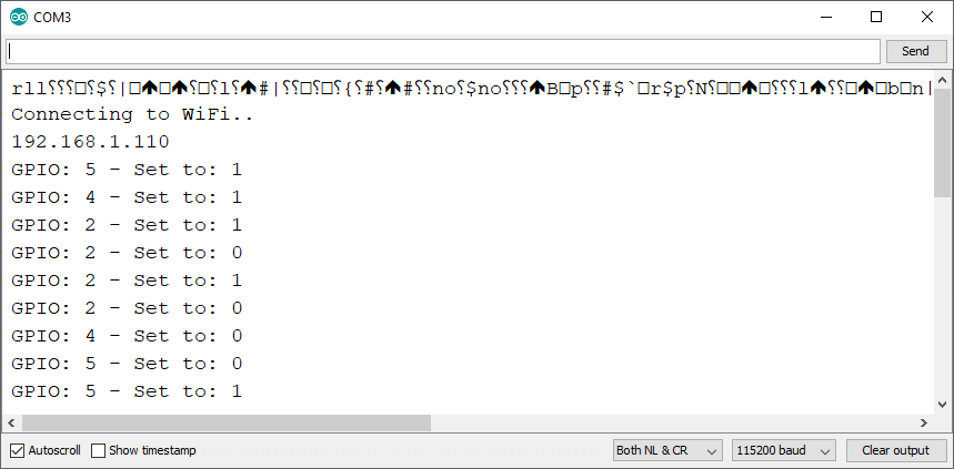
Once you’ve uploaded the code to your ESP8266 async web server, launch the Serial Monitor with a baud rate of 115200. Press the on-board RST/EN button, and you should receive its IP address.
Open a web browser and enter the ESP IP address. This will grant you access to a similar web page.
Utilize the toggle buttons to manage the ESP GPIOs. Simultaneously, you’ll receive the following messages in the Serial Monitor to aid in debugging your code.
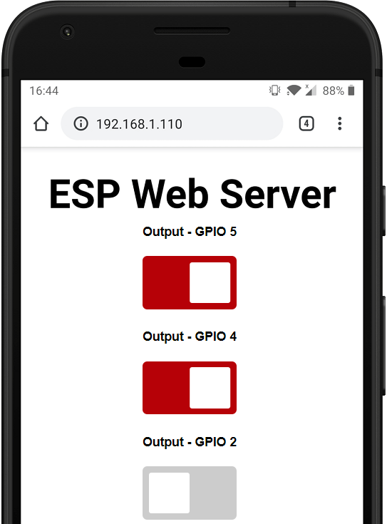
You can also access the web server from a browser on your smartphone. Upon accessing the web server, it will display the current GPIO states. Red signifies that the GPIO is activated, while gray indicates that the GPIO is deactivated.
Wrapping Up
In this tutorial, you’ve gained insight into building an asynchronous web server with the ESP8266 NodeMCU board to manage its outputs through toggle switches. Upon accessing the web page, it promptly reflects the updated GPIO states.
Explore other web server examples utilizing the ESPAsyncWebServer library that you may find intriguing:
- BMP388 Barometric Sensor Setup for ESP8266 NodeMCU (Arduino IDE)
- Arduino IDE Tutorial: Using HC-SR04 Ultrasonic Sensor with ESP8266 NodeMCU
- Master DC Motor Control: ESP8266 NodeMCU and L298N Driver Tutorial
- ESP8266 NodeMCU: MAX6675 Amplifier for Precise Thermocouple Readings


